P1

P 1

TFCS

Collin Stedman, Raymond Zhong, Farhan Abrol, Dale Markowitz

Ideas

  • NFC device that allows user to “transport” documents and websites from one computer to another.
  • Habit-acquisition system.  Tag physical objects like dumbells, medicine bottles, etc with RF tags or microcontrollers, and use them to detect and log users’ interactions with these objects.

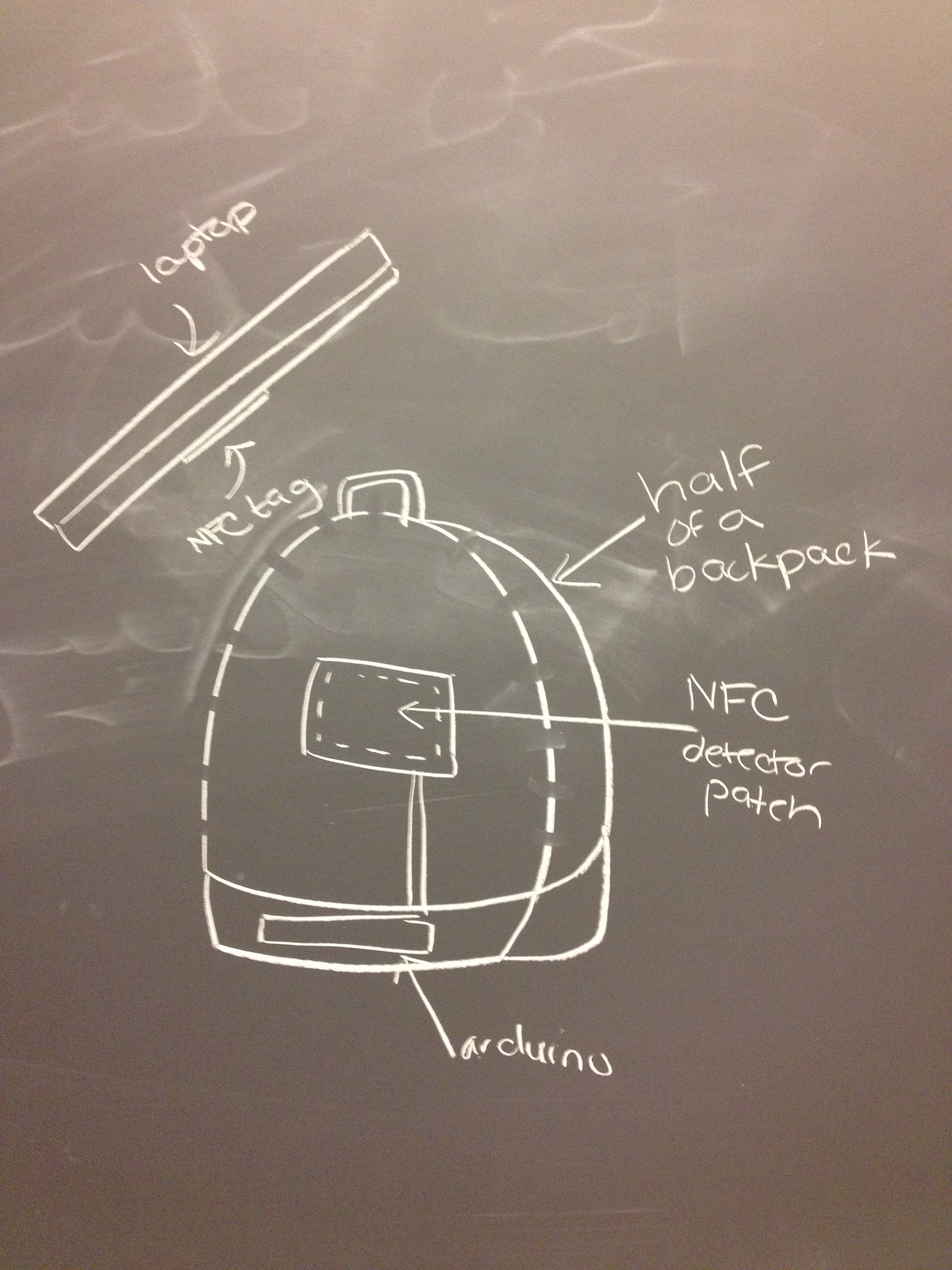
  • Forget-me-not backpack. If it is zipped without an NFC-tagged laptop, it beeps to alert its user he/she has left something behind.

backpack

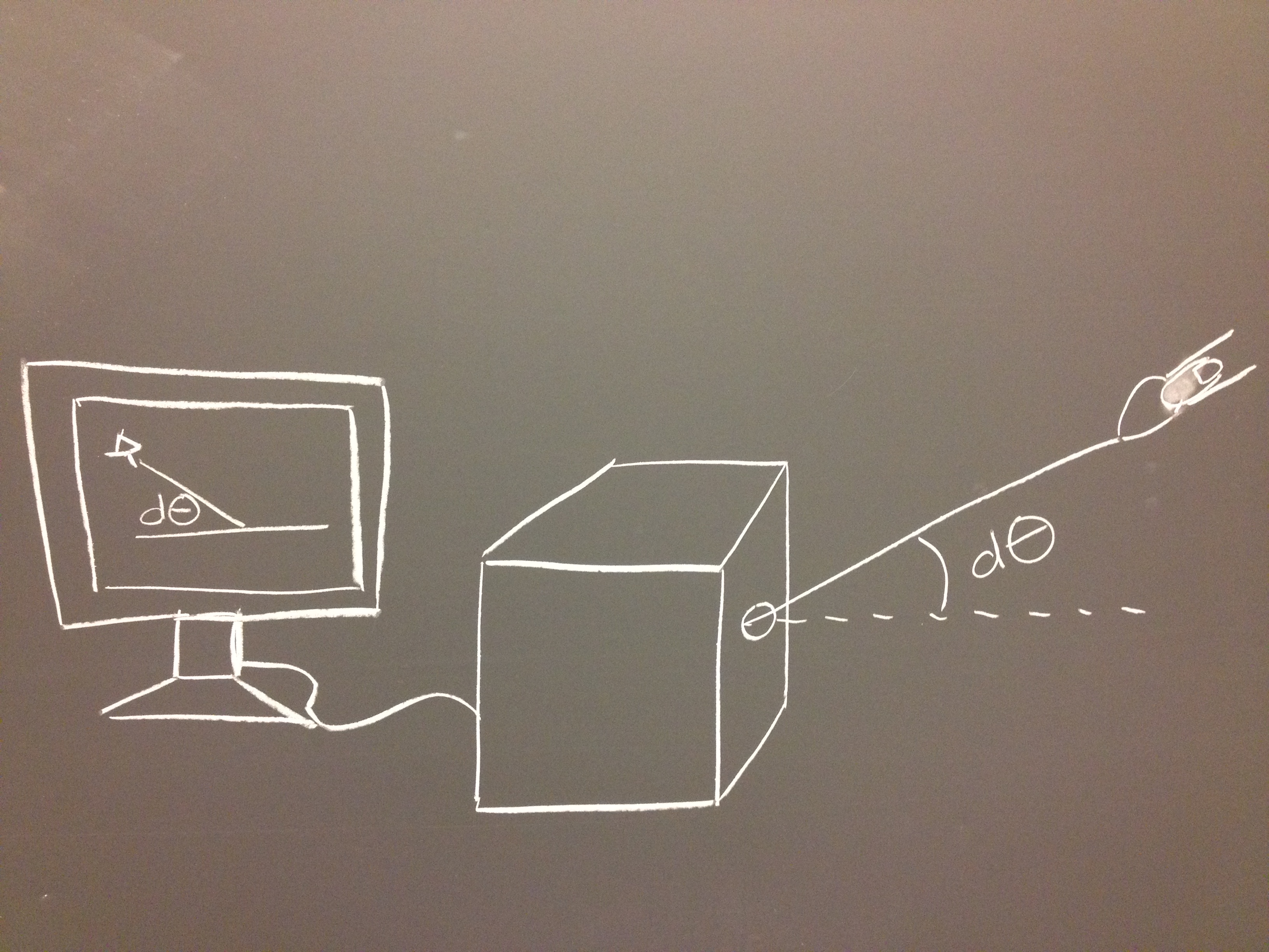
  • Portable 3D pointer/mouse which consist of a string whose tension is measured to determine its position in 3D space.

  • Interface for navigation through multiple degrees of graphs (such as WordNet) with gestures using Kinect/Leap Motion.
  • Real-time tracking of facial microexpressions using a wearable camera, to provide instant feedback on social interactions and crowds.
  • Real-time tracking of facial microexpressions using a stationary webcam, to track energy and dynamics in a room during meetings, lectures, etc.
  • Intelligent conference tables that transfers powerpoints/handouts to and from users who place their devices on it.
  • Augmented-reality phone apps that overlay location data from Facebook, Linkedin, etc on the real world, like Yelp Monocle but with open data integrations.
  • Panoramic photography application for iPhone, which allows tagging things around you and immersively recreating the place where you took the photo.
  • Pen peripheral device for iPhone, which has a pencil tip and can write on paper, but also saves digital copies of what users have written.
  • Add electrical/magnetic field sensing to an iPhone or Pebble, and use it to provide an additional sense through vibration, tension, etc.
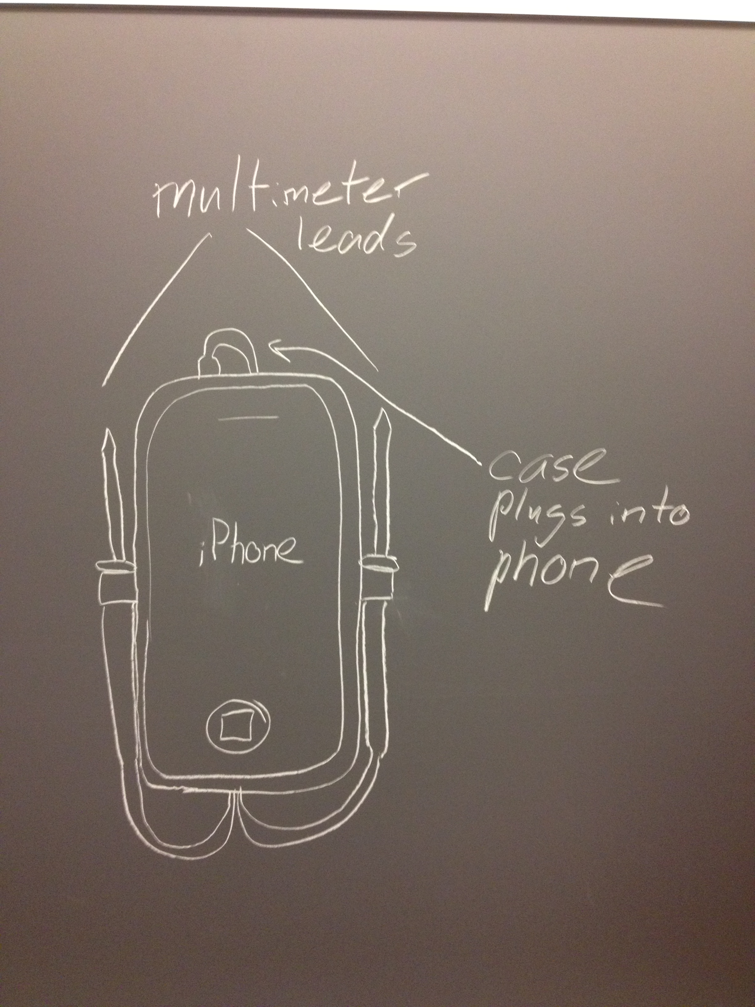
  • iPhone peripheral multimeter attachment

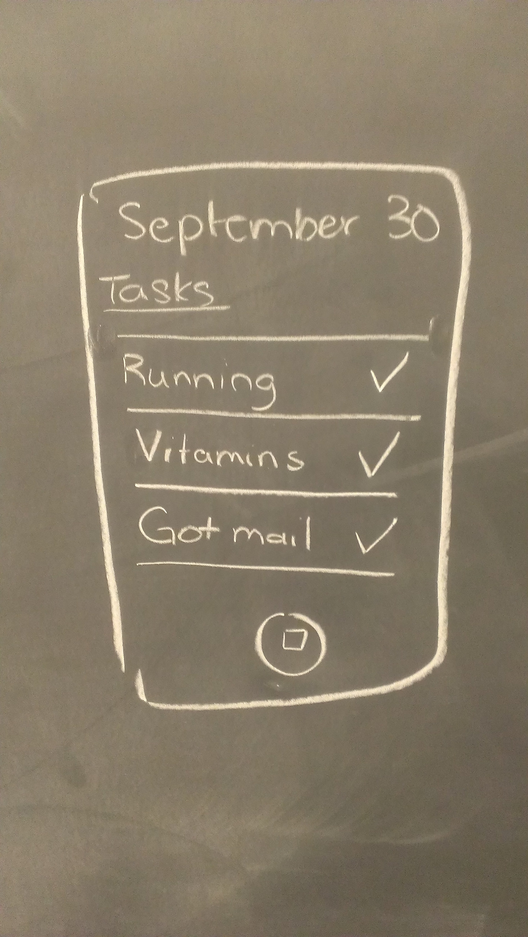
  • Geo-aware reminder app: App that reminds you to do tasks when you are in the appropriate location, sensed using GPS.
  • Public computer setup that senses’ users presence using face recognition and/or NFC, and automatically loads their personal desktop from the cloud.
  • An audio looper that uses Leap/Kinect to control dynamics, pitch, etc.
  • Virtual plants and creatures that simulate the health of real things, like work, schedules, or relationships (as measured by online communication). Best if a clear interface for tracking many different things.
  • Interactive canvas that can be touched or walked on to draw stories or animated art/videos/slideshows.
  • SMS enabled door lock – users text their friends keys which enable the friends to open the lock.
  • A tangible interface for tangibly representing and manipulating object-oriented programming constructs.
  • Input/output integrations between two computers that allow them to work together seamlessly.
  • Keyboard gloves. Design a different keyboard that allows typing from memory.
  • Digital business cards that are exchanged by phone via NFC.
  • A game played on a digital surface where the physical location and orientation of game pieces upon the board causes different game behaviors, events, and outcomes.
  • Photo frames whose photos are static until users stop to look at them, at which time the photos become videos and possibly react to the observer(s).
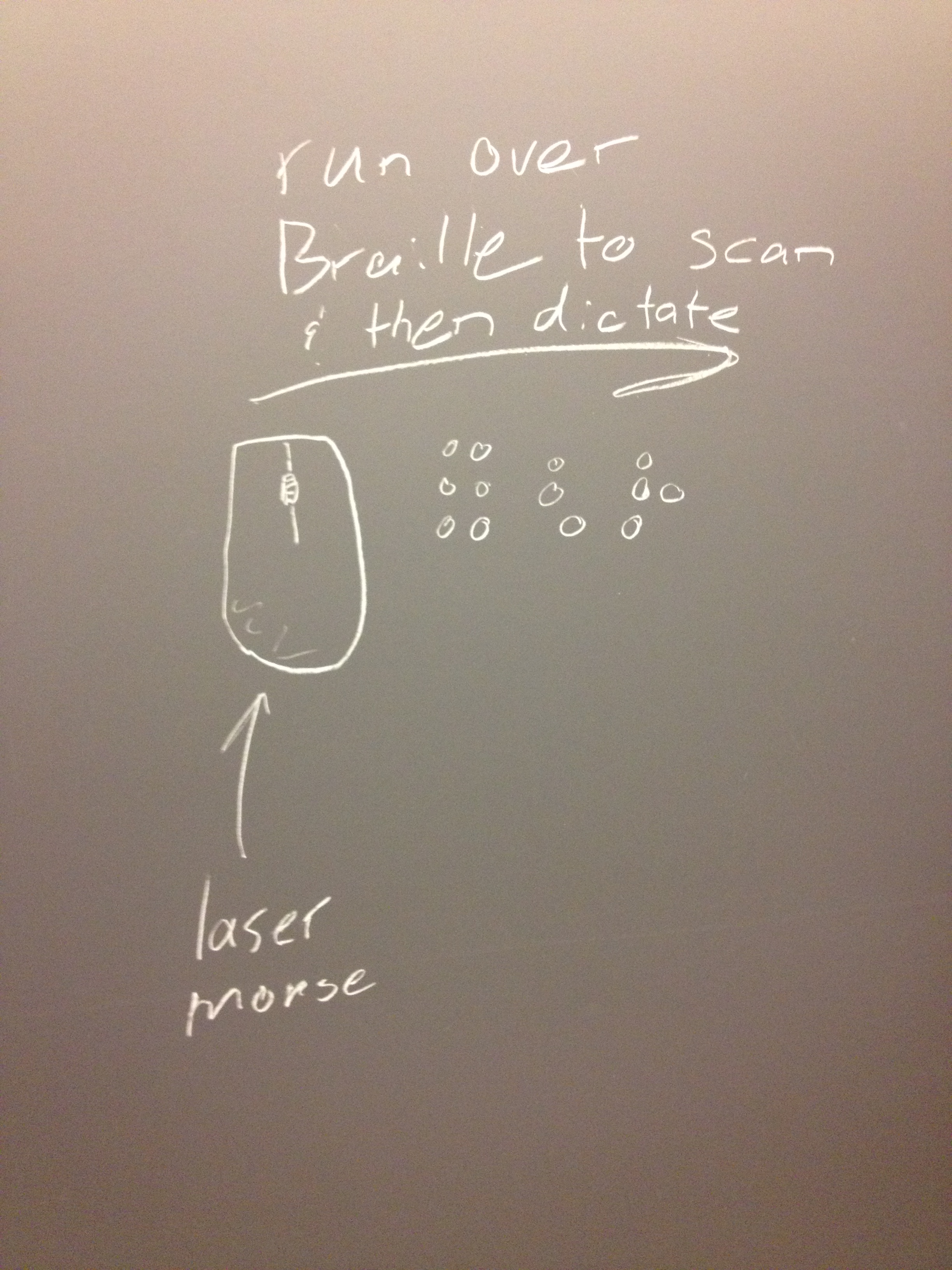
  • 3D scanner which reads and interprets braille.

  • A petlike robot which is meant to be a dynamic presence in the homes of people living alone.
  • Wifi-detector necklace/keychain, which glows when open wi-fi is available, or for important calls.

  • Kinect program which allows users to “walk through” panoramic google maps.
  • NFC-key bracelet, which stores NFC keys like a virtual keyring would.
  • Multiuser NFC laptop lock screen which tracks recent users of the computer, retaining traces of their presence and usage of the computer. (Useful for making computer applications more discoverable, if people can see what software is used at a certain workstation.)
  • Flash drives that plug into a computer and download content from Internet livestreams, and replay them until they are exhausted and must be recharged.
  • Lights that automatically turn off when user gets into bed (detects this with pressure sensor)
  • Chandelier that displays when user receives an email, Tweet, etc with different color LEDs.

  • Persistence of Vision machine that sits on users desks, displays tweets, email titles, etc.
  • Lecture attendance taker using NFC login.
  • Headband that measures user’s concentration and vibrates to alert them when they lose concentration (for use in lecture, studying, etc).
  • Posture monitor using a stretch sensor, which vibrates to alert user when he/she is slouching.
  • Musical device that consists of streams of water (water harp, for example).  Perhaps for hearing-impaired users to visualize and create music.
  • Controllers for complex theater lighting configurations using gestures/tactile interfaces.
  • Redesigned controls for mixers and synthesizers, perhaps gesture-based using Kinect.
  • Interactive table that can be drawn on and that makes noise when users touch it, also responding to pressure of touch.
  • A set of triggers for safely receiving a delivery carried by a small quadrotor/helicopter.
  • A gestural user interface used to provide navigation instructions for a robotic reconnaissance drone before it is deployed.
  • Intelligent teapot that brews tea when it reaches the right temperature.
  • Canvases that interactively display text/poems/etc through gestural input. Think interactive museum exhibit but with text.
  • Journal that automatically logs daily temperature, pulse, location based on data taken by phone, fitbit, etc.
  • Directional sensing of wifi or cell signals – overlay where wifi or cell signals are coming from on a webcam view or Google Glass.
  • Virtual spatial interface across multiple computer screens: ability to throw virtual objects from one screen or computer to another in physical space using gestures.
  • Object oriented programming language which is embodied by physical lego-style blocks. Each block corresponds to an object with a series of functions. Plugging blocks together in different ways creates complete programs.
  • Shoes that sense and warn athletes of poor posture in real-time and historically.
  • Using a sheet as a screen. Video camera detects indents or ripples in sheet, interprets command and projects new image on sheet.
  • 3D scanner, and interface for virtually rearranging scanned objects in e.g. a room.

Our Choice

Habit Tracking for Object Interactions

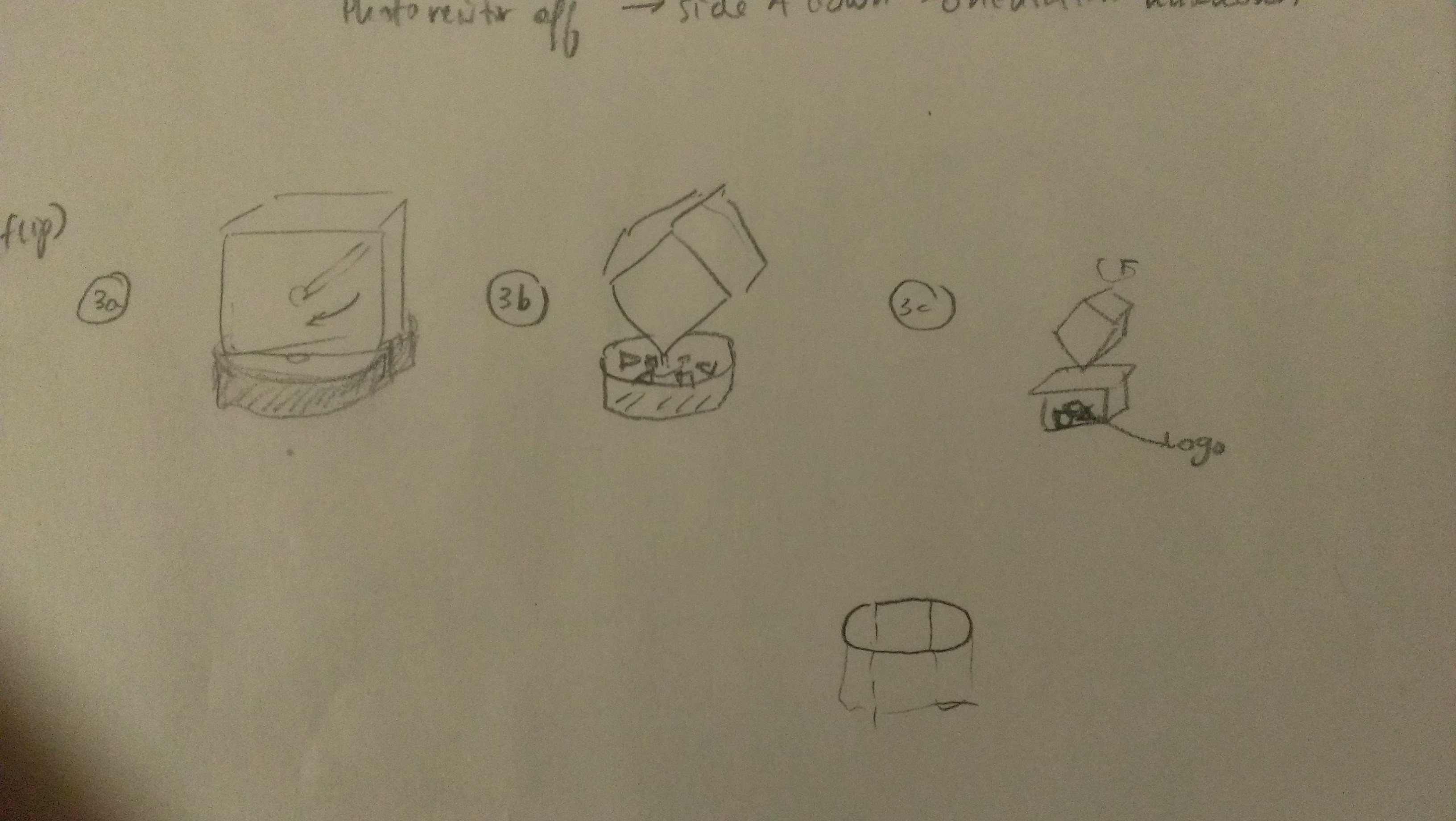
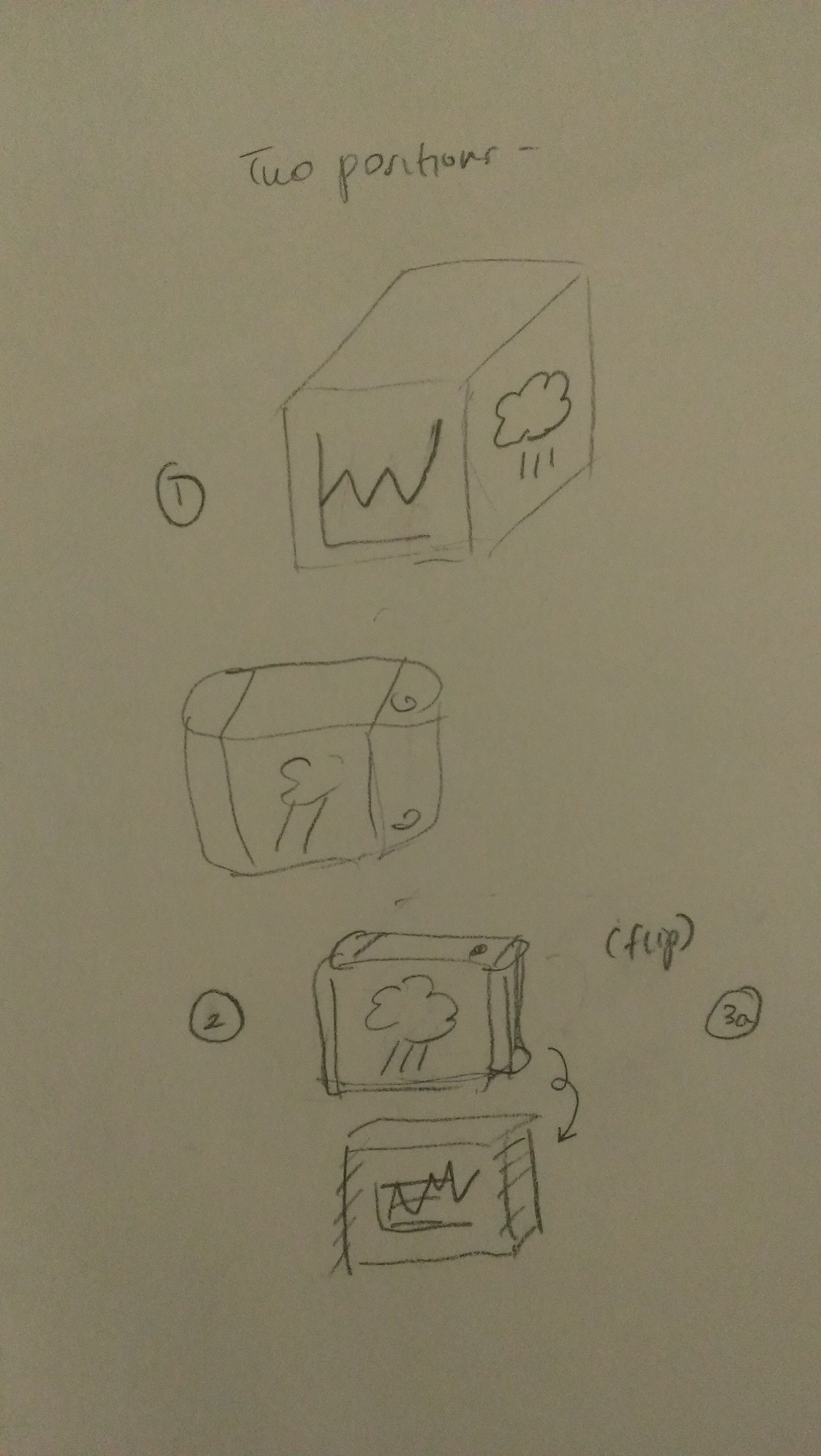
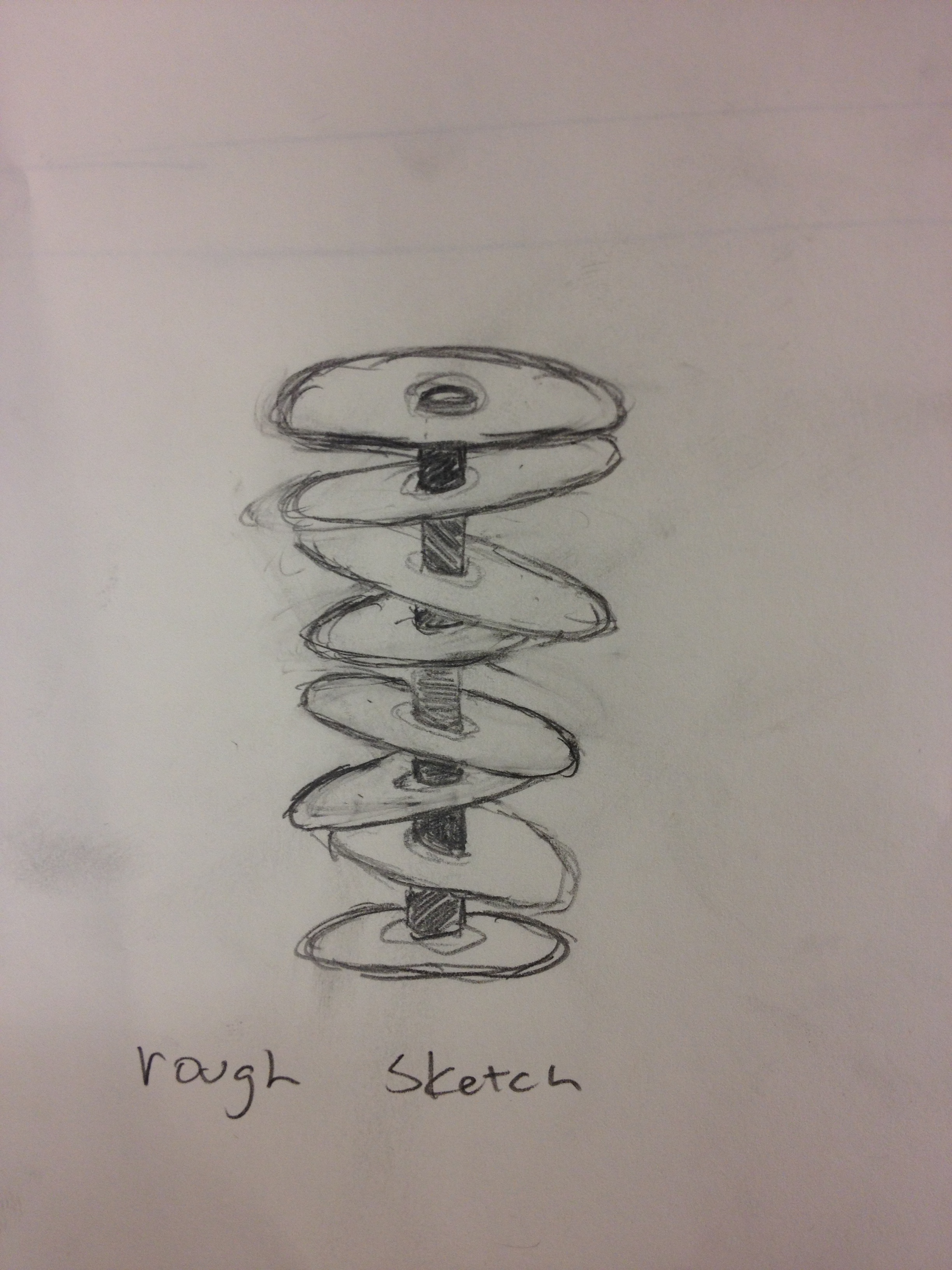
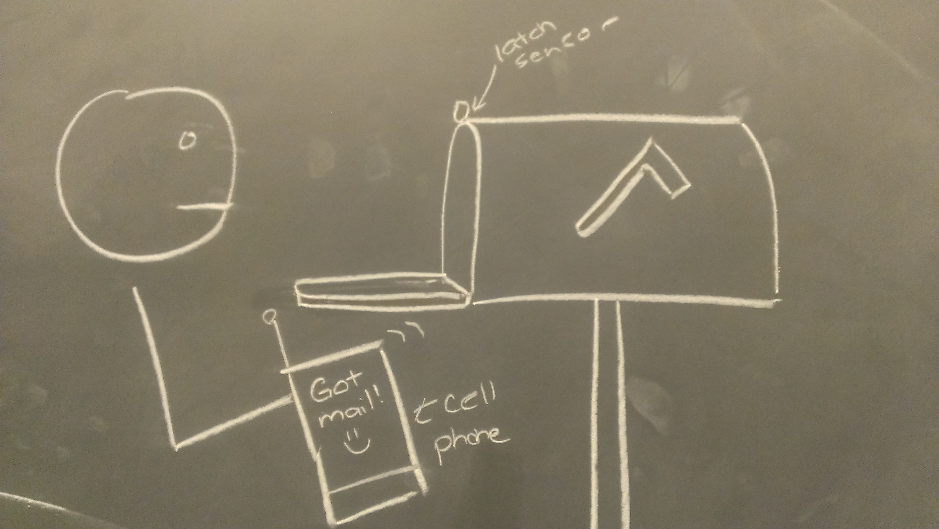
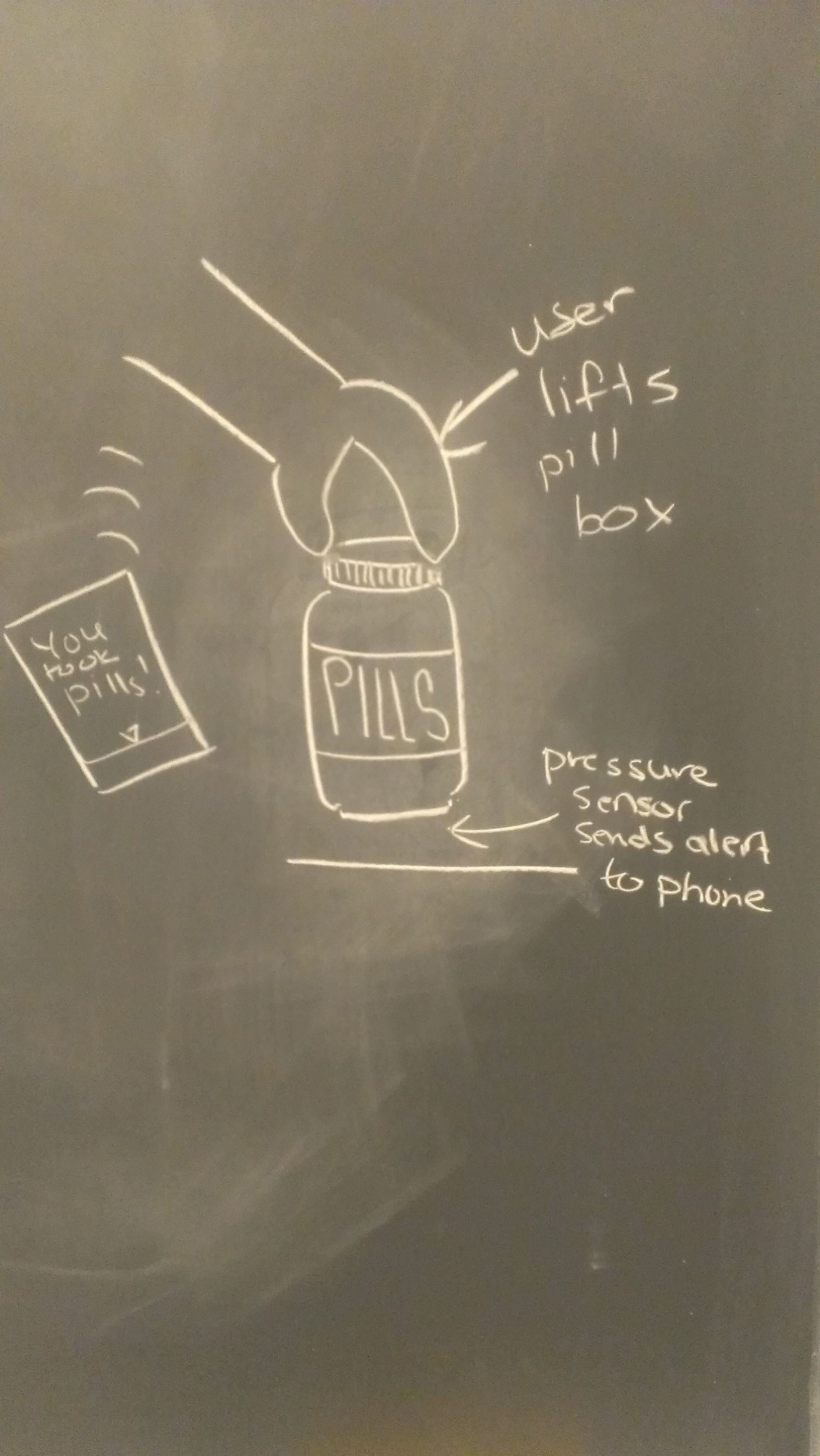
We will create a variety of sensors to be attached to everyday objects like medicine boxes and exercise equipment, which detect when they are disturbed and update a habit-tracking application on your phone or computer.

We thought of many physical computing ideas, and chose the one that enabled the most interesting interaction cycle between the user and computer. Dale and Collin were interested in using NFC tags to remind themselves when they forgot to bring things with them. Raymond noticed he left things untouched that he wanted to use, like vitamins, whey, and dumbbells. We realized that it’s hard to profile what objects should be on someone at all times, but it is much easier to couple everyday interactions with objects like medicine bottles and dumbbells to a computer. What if those objects could remind us when they were left unused? This is useful; it would solve problems for anyone on a medical regimes or trying to build a new habit. It also enables some of the most interesting human-computer interactions among all the ideas we considered, since it it imbues common objects with intelligence which can go far beyond sensing disturbances, enabling a whole class of interactions between people and things around them.


Target Users and Context

Habit tracking serves strong needs for a few user groups. The elderly and those suffering from Alzheimer’s would benefit massively from reminders for their daily habits. For both the elderly and the infirm, daily medication schedules are vital; both overdosage and underdosage are unacceptable. Elderly individuals frequently use pill boxes labeled by day in order to remember which medicines to take on a particular day of the week. While this humble solution is simple and reliable, it does not provide active reminders and is only effective when used regularly. Even more importantly, the elderly population is provided with very few tools for remembering non-medical habits or behaviors, such as calling a family member, attending a scheduled appointment, feeding a pet, or checking the mail. This demographic is likely to have few but more significant uses for mobile or desktop computers, like calling and messaging relatives or reading news.

Another group of people who would benefit from habit tracking is athletes. In order to prepare for a marathon, be in peak shape for a championship, or simply maintain physique, athletes must be diligent in their workout routines. They need to remember to workout with a certain frequency, or want to make sure they they work out at a certain time of the day and for a certain amount of time. Most importantly of all, they need to make sure that they manage to maintain whatever changes they make to their established routines. The category of athletes extends to larger groups like students or the general population, as we are all too familiar with making resolutions to go to the gym or floss every day. Many people are interested in either acquiring new habits or reinforcing existing ones.

Problem Description

Our product solves two general problems. The first is struggling to acquire habits, which requires a solution that is reliable and easy to use. A reminder system must not fail upon losing Internet connectivity, although it could expect a phone to stay powered on, and it should not disrupt existing non-technological solutions like pill boxes. The habit tracker will be used mostly at home, or perhaps at work, by people with limited experience with technology. The system should require little maintenance, although users are not likely to be busy.

Another user segment is those who would like to acquire new habits, like flossing, taking vitamins, or exercising. These users currently use Seinfeld-style calendars where they cross out days when they have accomplished their goals, or habit tracking apps that are general-purpose (like Lift or Beeminder) or specific (like RunKeeper). Calendars are limited in how many habits they can track and do not provide reminders. Habit tracking apps require a superfluous interaction beyond the actual activity of the habit. Since these users are likely to have limited motivation during most times (but high motivation occasionally), a lower-friction interaction is beneficial for them.

Choice of Technology

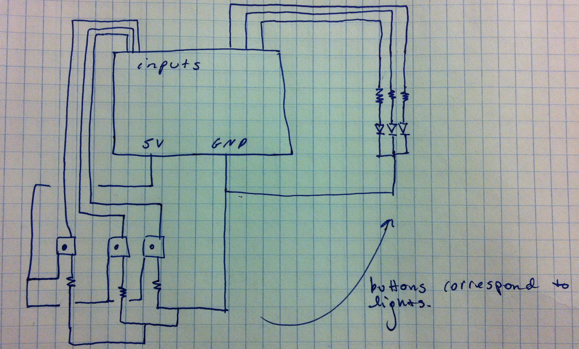
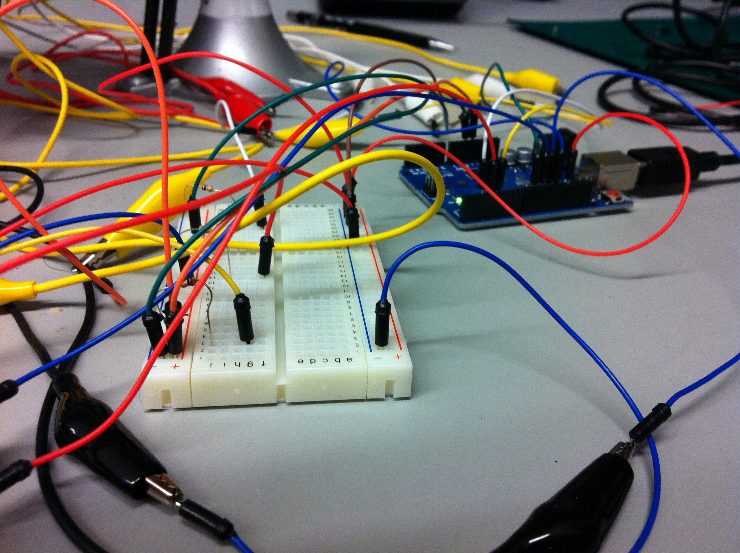
Our system will use a combination of platforms to sense and track object interactions. The frontend of the app will be a smartphone or web app which lets you identify and track the habits and objects that are being tracked. It generates reminders and alerts for objects that haven’t been disturbed by the user in a set time period, and provide reminders to enforce important actions/habits the user is trying to follow.

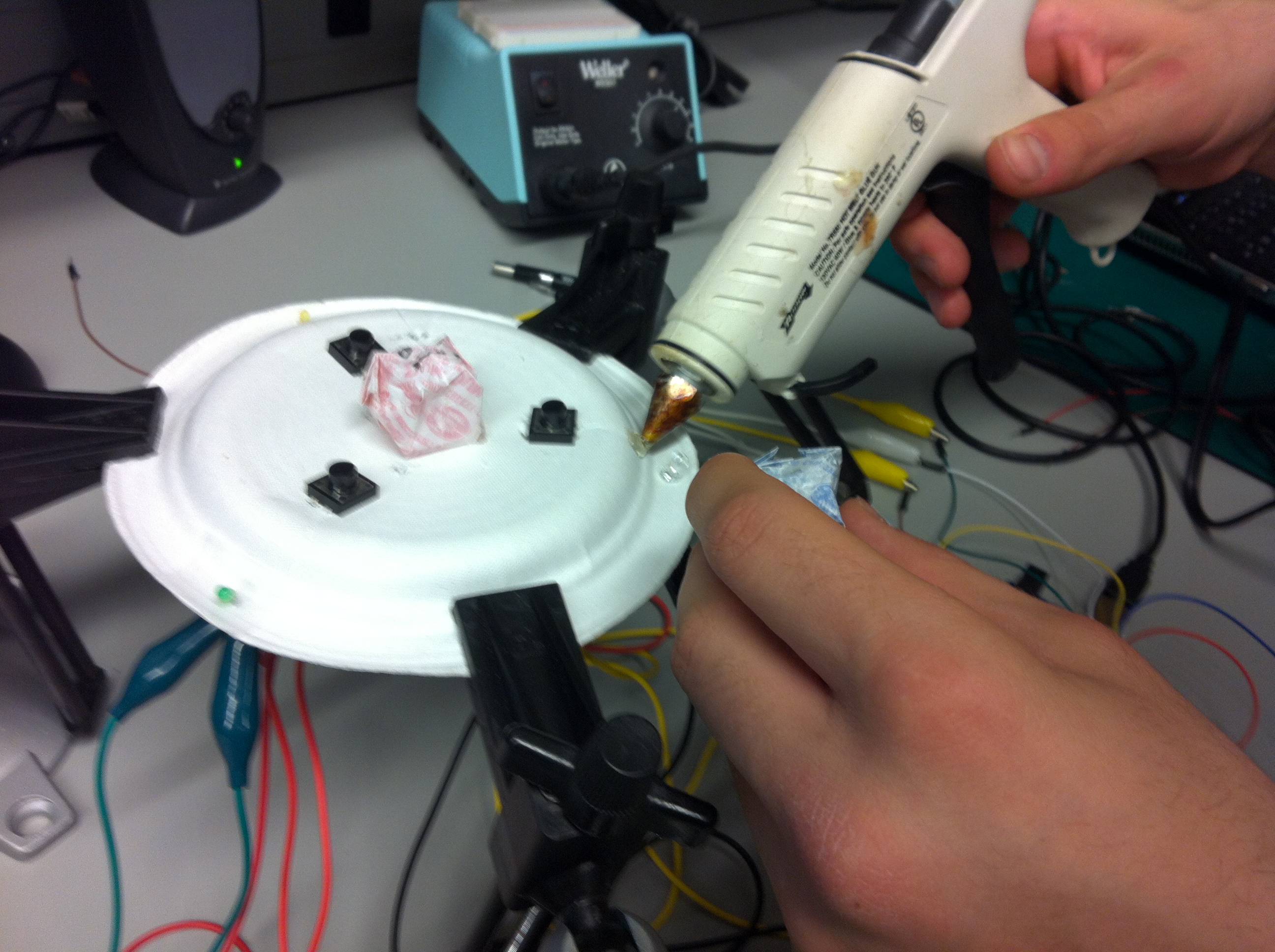
The sensors must detect usage of the object; since the interaction varies between object, we would use a number of sensor integrations.

  • Weight-sensing pads for: pill boxes, dumbbells, laundry bags, sports equipment
  • Tilt/shake sensors for: dental Floss, hygiene items, tilt-sensors for pill boxes
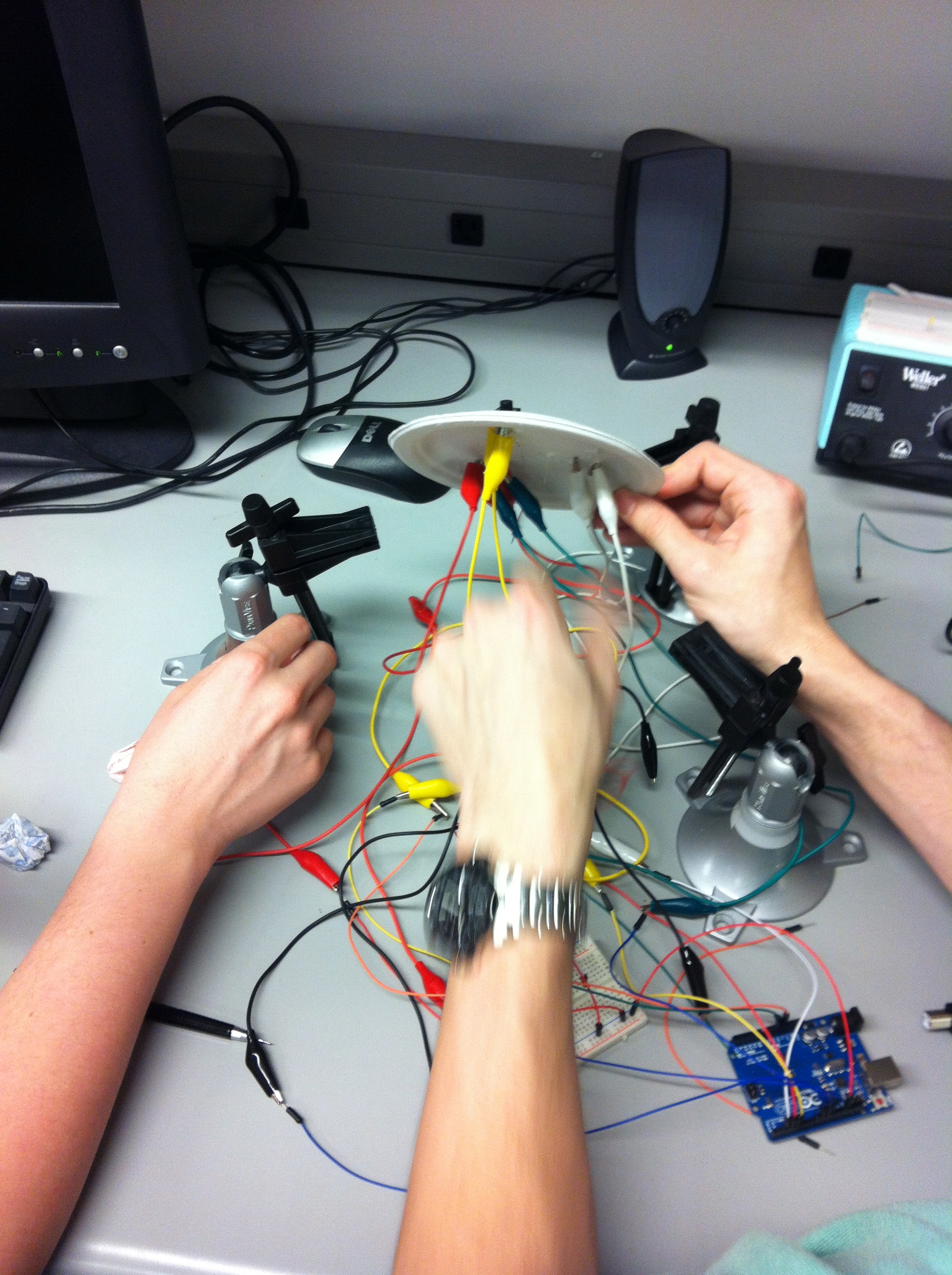
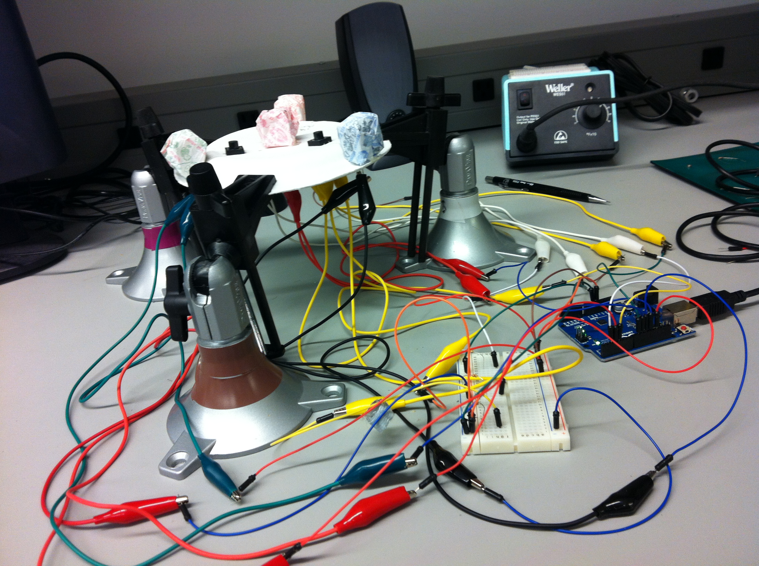
  • Light sensors for: unused rooms
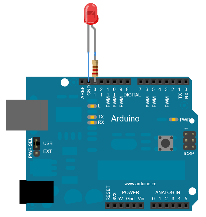
  • Electrical sensors for: windows, doors, lights

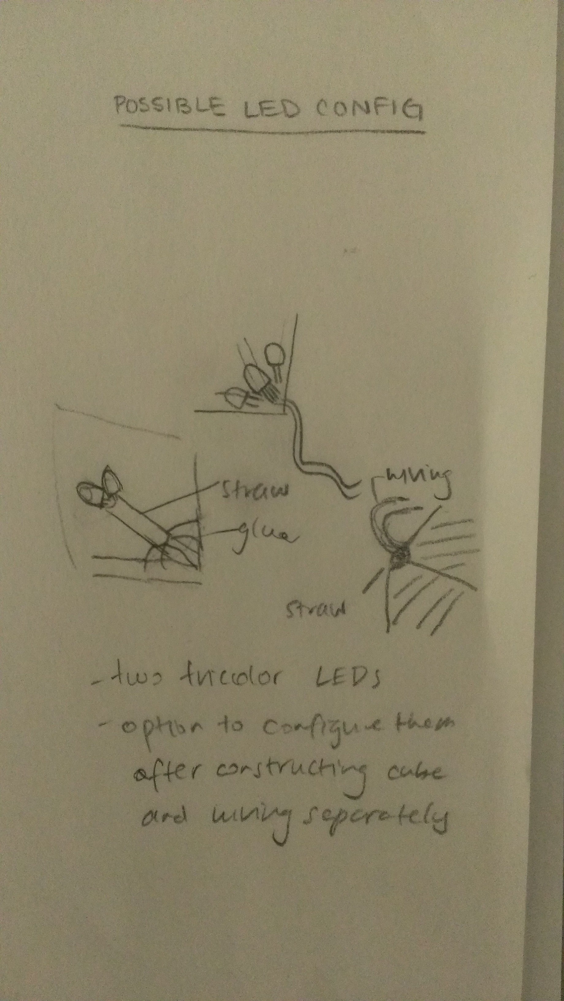
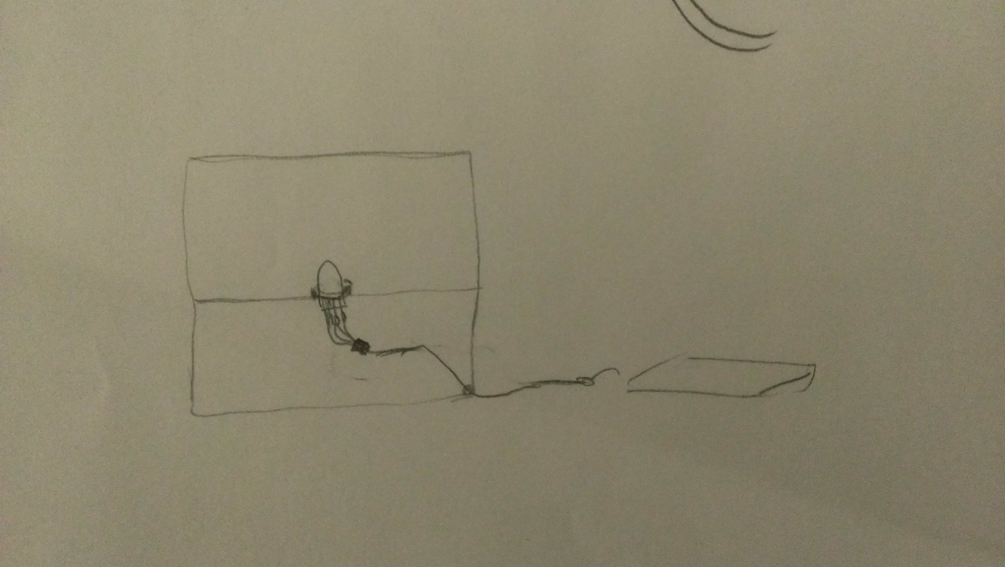
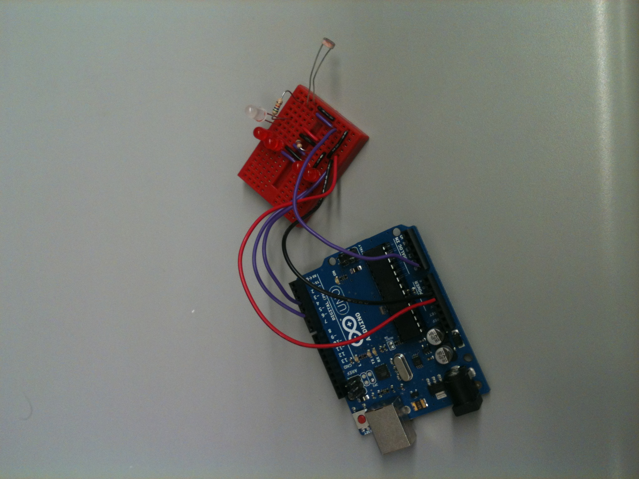
More than just force-sensors, these should sense time, so we can also track how long the object in question was used for. These sensors could be connected to microcontrollers which broadcast a signal. For a more polished system, we could use RF (radio frequency) tags and transmitters to reduce cost and size. The information could then be relayed to a hub or an Internet connection.

NFC-based sensors and NFC-reader phones are one other feasible implementation for the system. NFC tags are cheap and easy to tag an object with, and the data error rates are close to zero. They are also passive, requiring no power supply, which is ideal for sensors that you would attach to objects of daily use. The caveat of using an NFC based system is that the reader (phone) needs to be physically close (3-4 cm) to the tag in order to detect it and get data. This limits the kinds of information that we can get about patterns of usage of objects to only situations where you would physically touch the object with your phone to register a reading. Another implementation choice following in the same vein is using RFID-tags, active or passive as the sensors, and an RFID reader for receiving data.

Light DJ

Light DJ
Ryan Soussan, Bereket Abraham, Lauren Berdick, Andrew Ferg

Description
We used Processing and the Arduino to map a color wheel to the multi-color LED. On the computer screen, Processing displayed 3 overlapping circles, which were red, green, and blue. The mouse’s distance from each circle’s center corresponds to the intensity of that color. We then send those values to the Arduino and use them to set the brightness of each LED color. The only problem we encountered was the mismatch between the RGB mixing from Processing’s color values and the actual mixing of red, green, and blue light. When the LED mixes all 3 colors at equal intensities, it creates white light; however, mixing red, green, and blue in Processing creates a dark black-brown, creating a discrepancy between the GUI and the actual LED output.

Parts
1 computer (to run Processing and Arduino)
1 Arduino Uno microcontroller
1 multi-color LED
4 jumper wires
3 330 ohm resistors
1 small breadboard
1 piece of wax paper to diffuse the LED

Instructions

2 of our design sketches:

LightDJ3LightDJ4
Install Arduino and connect the board to you computer. Use the Blink and Dimmer tutorials to make the LED turn on. Remember to include a resistor for each pin. Use three PWM pins (~) so that you can modulate the brightness of the LED (these let you mimic an analog signal using a digital output). Test the different ends in order to match each pin to a certain color, and then encase the LED and mini-breadboard in wax paper to diffuse the light.

Front and back views of our little contraption:

LightDJ

LightDJ2

Now go to Processing and make your GUI. We represented the color wheel with 3 circles in a triangle (go to the color tutorial at processing.org). Make the circles slightly transparent so that they can overlap and mix. We then mapped the distance from each circle to the intensity of that particular color.

Our Processing GUI:

LightDJ5

The last step is to send the Processing color values to the Arduino using serial communications. Convert the color values calculated by Processing into bytes, to ease serial communications, and have the Arduino read the bytes one at a time, and set them to the corresponding color values. (For debugging, it may be useful to have the Arduino print the RGB values back to the serial port)

Source Code

Arduino:
#define RED 6
#define GREEN 10
#define BLUE 3

int rByte = 0;
int gByte = 0;
int bByte = 0;

void setup() {
pinMode(RED, OUTPUT);
pinMode(GREEN, OUTPUT);
pinMode(BLUE, OUTPUT);
Serial.begin(9600);
}

void loop() {

while (Serial.available() < 3) {};

// if there are any serial bytes available to read
if (Serial.available() > 0) {
// then read the 3 bytes, sent in order R,G,B
rByte = Serial.read();
gByte = Serial.read();
bByte = Serial.read();
}

// write the RGB values to the LED outputs
analogWrite(RED, rByte);
analogWrite(GREEN, gByte);
analogWrite(BLUE, bByte);

//Serial.write(rByte);
//Serial.write(gByte);
//Serial.write(bByte);
}

Processing:
import processing.serial.*;

int r = 390;
float rr = 0;
float gg = 0;
float bb = 0;
int b1,b2,b3 = 0;

Serial port;

void setup_port() {
port = new Serial(this, Serial.list()[0], 9600);
}

void setup() {
size(600, 600);
colorMode(RGB, 255);
noStroke();

setup_port();
}

void draw() {
background(255);
//blue circle
fill(0, 0, 255, 255);
ellipse(300, 200, r, r);
//green circle
fill(0, 255, 0, 150);
ellipse(200, 400, r, r);
//red circle
fill(255, 0, 0, 150);
ellipse(400, 400, r, r);

rr = sqrt((400-mouseX)*(400-mouseX) + (400-mouseY)*(400-mouseY));
gg = sqrt((200-mouseX)*(200-mouseX) + (400-mouseY)*(400-mouseY));
bb = sqrt((300-mouseX)*(300-mouseX) + (200-mouseY)*(200-mouseY));

rr = 255 – rr;
gg = 255 – gg;
bb = 255 – bb;

if (rr < 0)
rr = 0;
//  else if (rr < r)
//    rr = 255;
if (gg < 0)
gg = 0;
//  else if (gg < r)
//    gg = 255;
if (bb < 0)
bb = 0;
//  else if (bb < r)
//    bb = 255;

fill(rr, gg, bb, 255);
ellipse(0, 0, r, r);

b1 = (int)rr;
b2 = (int)gg;
b3 = (int)bb;

byte[] rgb = {(byte) rr, (byte)gg, (byte)bb};

port.write(rgb);

println(“Sending:”);
println(b1);
println(b2);
println(b3);

if (port.available()  > 0) {
println(“Reading: “);
println(port.read());
}
delay(5);
}

Lab 0: Groovy Lava Lamp

Group Members

  • David Dohan
  • Miles Yucht
  • Andrew Cheong
  • Shubhro Saha


Description
In a moment of ‘70s nostalgia during our lab brainstorming session, we decided to build a lava lamp. Not only did we want to reproduce the brilliance of the original lava lamp, but also our objective was to creatively extend its capabilities. In particular, our innovative lava lamp allows the owner to change the lamp’s color/brightness with an interactive slider and switch between color/brightness modes witha push button. The milk and oil lava produced a unique texture of very fine bubbles which act as an excellent light diffuser. Our final product turned out to be a great success. It’s not perfect, but it changes color according to the user’s input and turns on when the room lights are turned off. The code written for this interactivity is our proudest feature, and there are several areas of improvement. The lava lamp is hardly robust—electrical connections inside the test tube had to be completed with paper clips because alligator clips were too large. With more time, we would’ve made it less obvious that the lamp is a crude Princeton water bottle with a test tube dropped inside of it. However, it demonstrates a proof of concept, and it is easily expandable in the event that one would like to use more LEDs or add more modes. Additionally, we could improve the smoothness of the mapping from linear values (from the soft pot) to the color wheel.

Photos of Sketches


We considered making a reaction time game with Arduino.

We considered making an LED change brightness in response to ambient light levels.

photo


This is our final schematic for the lava lamp.

Video

Here’s a YouTube video of our final system in action.

Parts

  • Arduino Uno
  • Small water bottle
  • 12 mL test tube
  • Tricolor LED
  • 5 330-ohm resistors
  • Photoresistor
  • Button
  • Softpot
  • Vegetable Oil
  • Teaspoon of milk


Instructions
There are four components to this build: the lava and its container, the tri-color LED light source, the interactive controls (i.e., the softpot, photoresistor, and button), and the Arduino with associated code. We first built and tested the light source with the Arduino before putting it into the test tube. When building the light source, make sure that the way you connect the LED to the rest of the circuitry makes a difference: it needs to be slim enough to fit inside a test tube. To build the light source:

  1. Connect pin 9 on the Arduino to a 330-ohm resistor, and in series connect the cathode on the tri-color LED corresponding to the red LED. For the second connection you will want to use longer cables so that they can reach from your breadboard to the LED once it is suspended in the lava lamp.
  2. Repeat step 1 with pin 10 on the Arduino to the green cathode and pin 11 on the Arduino to the blue cathode.
  3. Connect the tri-color LED anode to ground, again using a long cable.
  4. Because these wires all have to be very close to one another inside of the test tube, we recommend using a small amount of electrical tape between connections so that you don’t short out any connections.

To build the interactive component (softpot and button):

  1. Connect the softpot to the breadboard with pin 1 at 5V+, pin 2 to A1 on the Arduino, and pin 3 to ground.
  2. Connect the button using a 330-ohm resistor according to the Arduino Button tutorial (http://arduino.cc/en/tutorial/button).
  3. Connect the 5V+ to a 330-ohm resistor in series with the photoresistor. Connect A0 on the Arduino to the conductor between these two resistors, and connect the other end of the photoresistor to ground.

To build the lava lamp:

  1. Fill the bottle with half water, half vegetable oil up to about ⅘ of the way.
  2. Add in approximately a teaspoon of milk.
  3. Shake vigorously.
  4. The resulting mixture should have a slightly yellow/white color but also have a large number of small bubbles (resulting from the mixture of water and oil).

Assembling the final product:

  1. After finishing the LED assemblage, insert the LED into a test tube such that, when the test tube is lowered into the bottle, the LED will be approximately half-way down the bottle. The point of the test tube is to keep the LEDs dry and away from the oil-milk lava. If you’re having trouble (as we did), you can try a larger test tube.  Ideally, you should solder and insulate the leads, but since we are not allowed to solder, our makeshift solution was to use paper clips to extend one of the cathodes so that we could connect to it using an alligator clip. Also, a small amount of oil on the inside of the test tube acts as a lubricant, so it is then a bit easier to slide the LED assembly inside.
  2. Lower the test tube into the lavalamp, and use tape to hold the test tube in place inside the bottle.
  3. Play!

Usage
There are 4 basic modes: one to set the color of the LED and one to set the brightness. Switching between modes is accomplished using the button. In the color mode, the softpot controls only the color of the LED along a color wheel. In the brightness mode, the softpot controls the brightness of the LED without affecting its color. The third and fourth modes are for cycling through different colors By the nature of the softpot, as soon as one stops touching the component, the resistance returns to a steady state. Instead of trying to identify instances when this happens, we also made a fifth mode that saves the current settings. In this mode, the softpot has no effect on the color or brightness. In the future, we might add indicator lights to identify what mode we are in at any given time, even though it is really easy to find out (just touch the softpot and see how the light changes).

Source Code

// Lava lamp code for HCI (COS 436/ELE 469)

/*
  The RGB LED has three cathodes and a common anode. Each cathode
  corresponds to a color in the LED and is independently
  controllable.
*/

//for color of the tricolor LED only. determines the size of the 
//set of values over which each color fades on/off while using the 
//softpot.
int range = 300;

/*
  In each set of variables RGBLED_xxxx and RGB_x_mid, the former
  corresponds to the pin being used for color xxxx. The latter 
  corresponds to the softpot value at which color x is at its greatest
  brightness.
*/
int RGBLED_Red = 9;
int RGB_R_mid = 100;

int RGBLED_Blue = 10;
int RGB_B_mid = 500;

int RGBLED_Green = 11;
int RGB_G_mid = 900;

//Arduino pinouts for each component 
int softpot = A0;
int photosensor = A1;
int button = 2;

//current color
int color = 0;

//current values for the intensities of each LED color
int rgb_r, rgb_g, rgb_b;

// brightness ranges from 0 to 1
double brightness = 1.0;

// mode is:
//   0: set color
//   1: set brightness
int mode = 0;

// psthreshold is the least amount of light needed to activate the lights
int psthreshold = 850;

// state variable is:
//	0: off
//	1: on
int state = 1;

//calculates the intensity of a color based on the current value of
//the softpot, the color’s RGB_x_mid value, and the range variable.
int getBrightness(double mid, double cur) {
  int t1 = abs(mid - cur);
  int t2 = abs(mid - (cur - 1024));
  int t3 = abs(mid - (cur + 1024));

  int test1 = min(t1, t2);
  int minimum = min(test1, t3);

  if (minimum > range) return 0.0;

  return 255 * (range - minimum) / range;
}

//sets the color for all three colors in accordance with the current
//softpot value
void setVals(int cur) {
  if (state == 1) {
	rgb_r = getBrightness(RGB_R_mid, cur);
	rgb_g = getBrightness(RGB_G_mid, cur);
	rgb_b = getBrightness(RGB_B_mid, cur);
  }

  writeToLED();
}

//sets the brightness of the LED according to the current 
//softpot value
void setBrightness(double cur) {
  if (state == 1)
	brightness = cur / 1024;

  writeToLED();
}

//actually sets the PWM pins to the values dictated by the current
//color and brightness
void writeToLED() {
  analogWrite(RGBLED_Red, rgb_r * brightness * state);
  analogWrite(RGBLED_Blue, rgb_b * brightness * state);
  analogWrite(RGBLED_Green, rgb_g * brightness * state);
}

//switch between modes
void toggleMode() {
  mode = (mode + 1) % 5;
}

//setup each LED and button
void setup() {
  pinMode(RGBLED_Red, OUTPUT);
  pinMode(RGBLED_Blue, OUTPUT);
  pinMode(RGBLED_Green, OUTPUT);
  pinMode(button, INPUT);

  Serial.begin(9600);
}

void loop() {
  // Check to see if there is light in the room using the
  // photoresistor. If so, set the output to 0. Otherwise, use the
  // softpot.
  int current_light = analogRead(photosensor);
  int current_soft = analogRead(softpot);
  int button_state = digitalRead(button);

  if (button_state == HIGH) {
	while (digitalRead(button) == HIGH);
	toggleMode();
	Serial.print(mode);
	Serial.print("\n");
  }

  if (mode == 0) {
	setVals(current_soft);
  } else if (mode == 1) {
	setBrightness(current_soft);
  } else if (mode == 3) {
	color = (color + 1) % 1024;
	setVals((int)color);
  } else if (mode == 4) {
	color = (color + 1) % 2048;
	setVals(color/2);
  }
}

A Game of Simon Sees

Group members:

David Lackey – dlackey@

John O’Neill – jconeill@

Horia Radoi – hradoi@

(Santhosh Balasubramanian)

Playing Simon Sees

The aim of our project was to create a wearable version of the classic game of Simon Says. As such, the goal of Simon Sees is to remember and duplicate the sequence of lights generated by the microcontroller. The player wears a pair of glasses with two lights, one on each side, which are diffused via straws to create a visible beam of light. The game begins by showing a light sequence of length 1, which the player must duplicate by pressing the corresponding buttons – lighting the straws to indicate his or her decision. After each successful level, an additional light is added to the sequence. When the user makes a mistake, a red LED light notifies the user, and he or she has to restart the game. Overall, we found our final implementation fairly successful, especially after decreasing the time between the lights in the sequence, which increased the amount of attention needed by the player. After spending time with our prototype and inviting additional users to participate, we discovered that future iterations should contain more than two sources of input/ouput and that the current interface for user input (two buttons) could be transformed into something more engaging and unique, such as auditory- or motion-based forms of interaction.

Click here to view our project in action!

Initial Design Sketch

Initial Design Sketch

IMG_20130213_230037

The Simon Sees interface. Note the red light used to notify a user when they make an incorrect move.

Players use the controller to indiciate which light they think is next in the sequence.

Players use the controller to indiciate which light they think is next in the sequence.

Additional Designs

1. Contextual Disco Ball

If our disco ball senses a low-light environment, it begins increasing the brightness of our LED’s (one red, one green, one blue,) which are placed inside of a semitransparent ball. The lights are pulsating, and the frequency at which these lights pulsate is determined by an interactive Processing interface.

sketch_ball

2. Slit Experiment

Using an LED light and a dark box with two thin vertical cuts in one side (at a known distance), generate an interference pattern on a wall by turning the LED light on inside the black box and pointing the side with the two cuts towards a wall (requires a dark room).

Page-01

List of Parts

  • 1 Arduino
  • 2 Breadboards
  • 2 Buttons
  • 3 LEDs (1 blue, 1 green, 1 red)
  • Alligator clips
  • 1 Pair of glasses
  • 2 Straws

Instructions

  1. Begin by properly placing the circuitry elements on the Arduino board. One button, which is used to trigger the left light, must use pin 13 and should be arranged to a schematic similar to that as described in the Arduino blogs. The button for the right light should be using pin 12. Our left, right, and red LEDs should be using pins 10, 11, and 9, respectively.
  2. In order to attach the LED’s to the glasses, use long wires that have been braided together. These allow us to alter where we place our LEDs while being fairly unobtrusive.
  3. Place LEDs in straws and tape them to the corresponding side of the glasses.
  4. Load the Arduino with the following code, observe the first light in the sequence, and copy – enjoy!

Code

/*
 Simon Says
 Repeat the sequence of lights given by the button inputs.
 */

// Constants 
int N = 10;
int RED_LED = 9;
int LEFT_LED = 10;
int RIGHT_LED = 11;
int LEFT_BUTTON = 13;
int RIGHT_BUTTON = 12;
int DELAY = 200;
int RED_DELAY = 1000;
// State variables
boolean isShowing; // Are we showing lights?
boolean leftLights[10]; // Each element is true for left, false for right
int i; // leftLights index
int level; // Game level

// the setup routine runs once when you press reset:
void setup() {

 // LEDs
 pinMode(RED_LED, OUTPUT);
 pinMode(LEFT_LED, OUTPUT);
 pinMode(RIGHT_LED, OUTPUT);

// Buttons
 pinMode(LEFT_BUTTON, INPUT);
 pinMode(RIGHT_BUTTON, INPUT);

// Init game
 reset();
}

// Reset game
void reset() {
 i = 0;
 level = 1;
 isShowing = true;
 generateLights();
}

// generate lights array
void generateLights() {
 randomSeed(analogRead(0));
 for (int j = 0; j < N; j++){
 leftLights[j] = random(0, 2);
 } 
}

// the loop routine runs over and over again forever:
void loop() {
 if (!isShowing) {
 checkInput();
 }
 else if (i < level && level <= N) {
 showLights();
 }
 else {
 // Stop showing lights
 isShowing = false;
 i = 0;
 }
}

// Check player input
void checkInput() {
 // Collect input
 int leftButtonState = digitalRead(LEFT_BUTTON);
 int rightButtonState = digitalRead(RIGHT_BUTTON);
 // Check
 if (leftButtonState == HIGH && leftLights[i]) {
 // Left hit
 i++;
 show(LEFT_LED);
 }
 else if (rightButtonState == HIGH && !leftLights[i]) {
 // Right hit
 i++;
 show(RIGHT_LED);
 }
 else if (rightButtonState == HIGH || leftButtonState == HIGH) {
 // Miss
 show(RED_LED);
 reset();
 }

 // Check level completion
 if (i == level) {
 i = 0;
 level++;
 isShowing = true;
 }
}

// Show lights
void showLights() {
 // Show lights
 if (leftLights[i++]) {
 show(LEFT_LED);
 }
 else {
 show(RIGHT_LED);
 }
}

// play light
void show(int led) {
 int d = DELAY;
 if (led == RED_LED) {
 d = RED_DELAY;
 }

 digitalWrite(led, HIGH);
 delay(d);
 digitalWrite(led, LOW);
 delay(d);
}

Lab 0: The Wondrous Weather Cube (our very own Companion Cube!)

Team members: Kiran Vodrahalli, Collin Stedman, Raymond Zhong, Dale Markowitz

02/19/2013

We created an Internet-enabled companion cube for your computer, which displays different kinds of information by glowing red or green. Depending on its orientation, and which labeled face is oriented upwards, our companion cube displays either stock readings of the NASDAQ or the outside temperature in Princeton. As the temperature or stock index changes, the Arduino inside the cube fetches updated data from the host computer it is connected to, and modulates the brightness of red and green LED arrays inside. We thought it would be a perfect match for the topic of the first lab, LED diffusors, and that it also makes a useful and elegant desktop accent.

Ideation and Design

We started by thinking about LED diffusers, and found that the most interesting applications for us related to using them to display or convey information. We then considered a number of physical interfaces, including a tree, a panel, and various geometric shapes. We settled on a cube because we expected users to want multiple sources of information from the cube, and we thought rotating the cube was a better interface than configuring it by computer, since it would make use of the different sides of the cube. Since we have some Arduino experience, adding Internet connectivity so the Arduino and computer could talk to each other followed rather naturally.

Construction

We found that there was scrap foam in many different places we looked – the upper levels of the E-Quad, the Architecture building, and Frist among others. We went with that, instead of making our cube out of paper, because foam seemed like an excellent prototyping material. It was easy to cut, already pre-formed into sheets, and most importantly fit together like a jigsaw puzzle, allowing us to assemble the foam simply by pushing metal leads into the joints. Eventually we would want to use a laser-cut enclosure for this kind of box.

Concerns and Conclusions

We would have preferred a better spectrum of colors from our cube, but we did not have enough tricolored LEDs to produce enough light to be visible through our cube. We ran into a number of problems because of the differences in brightness and voltage between red vs. green LEDs and indicator vs. lighting LEDs, but we managed to circumvent most of those because foam was such a great diffusing material and blocked little light. Finally, we observed that the Cube is sometimes slow to respond as we scrape data from the web, because of latency. So, we’d like to make it faster if possible.

We think our companion cube is pretty and works well. If we had developed the cube further, it would have more applications — possibly one for each side of the cube, including email notifications, facebook notifications, etc. — and it would use an orientation sensor rather than photoresistors on each side to figure out its orientation.

Design Sketches

Tetrahedron, Prism, some ideas for functionality

Tetrahedron, Prism, some ideas for functionality


Initial Designs: The Tree of Tweets

Initial Designs: The Tree of Tweets


Perhaps a rotating cube? With a base?

Perhaps a rotating cube? With a base?


More Designs for the Cube

More Designs for the Cube

Initial Design for LEDs inside the Cube

Initial Design for LEDs inside the Cube


LED inside the Cube

LED inside the Cube


Rice paper in the middle, cardboard outside

Rice paper in the middle, cardboard outside


Parts of the Cube

Parts of the Cube

More detailed description of how the cube fits together

More detailed description of how the cube fits together

Dimensions of the Cube Side

Dimensions of the Cube Side


Arduino and Breadboard inside the Cube

Arduino and Breadboard inside the Cube

Circuit Design:

Arduino Circuit for Port 5: The Red LED array

Arduino Circuit for Port 5: The Red LED array


Circuit for Arduino Port 3, the Green LED

Circuit for Arduino Port 3, the Green LED

The photocell input circuit

The photocell input circuit


The Final Product! :


The stock market is going down today :(

The stock market is going down today 🙁


The weather is warmish! (At least, more than 33 degrees F! Winter at Princeton.)

The weather is warmish! (At least, more than 33 degrees F! Winter at Princeton.)

Video:

Our Companion Cube Working!

Parts we used:

4 Red LEDs, 1 White LED,  Green marker, Arduino Board, USB Cable, MacBook Air, Wires, 5.6 KOhm resistor, 560 Ohm resistor, photosensor, glue, styrofoam, breadboard

Tools we used: Wire strippers, Multimeter, Scissors, Razor

We also used some Python libraries, as documented in the code.

How to make your very own Wondrous Weather Cube:

You’ll need the parts given above, as well as the code given on the GitHub repo listed below. Assemble the circuit given in the circuit diagram included above. Hopefully the product should look similar to the picture of the completed circuit provided above. Then, build the cube by cutting the Styrofoam squares as shown in the design pictures. Glue the sides of the foam together. You may have to cut a small hole for the USB cable. Then, put the Arduino into the cube, and connect to a computer. First run the arduino code (weather_nasdaqCube.ino), then run the Python code (cube_handler.py). Flip the cube over to test modes. Voila! You now have your own working Wondrous Weather Cube!

Some sources:

http://apexlogic.net/code-bank/python/pyserial-example/ http://docs.python.org/2/library/re.html http://pyserial.sourceforge.net/pyserial_api.html#module-serial


Documented Source code: https://github.com/kiranvodrahalli/WondrousWeatherCube


Training Aid for Drag Racers

John Subosits

Here are some ideas for the third part of the lab.  Finding a way to make the diffuser useful was difficult.

img001

Click on the picture for a better view.

I decided to build the first idea, a device to improve the reaction times of people who drag race.  Three LED’s, red, yellow, and green were used to simulate the “tree” of lights that is used to signal the beginning of a race.  Several pieces of cellophane tape were used as a diffuser for the LED’s although napkins and a water bottle were also considered.  The red light illuminates, the yellow flashes three times, and then the green light comes on.  When this happens the person using the device pushes and holds the switch button supplied in the kit as they would the accelerator pedal if they were racing.  If they false start, only the red light illuminates while a clean start lights all three lights.  After a few seconds, the sequence begins again.  The system was reasonably fun to play with, and I consider it a success.  Some improvements would be adding additional yellow LED’s to allow them to stay lit for the countdown (more realistic), using a switch that mounts to the breadboard or one that has a form factor like a clutch pedal, and using the computer to report reaction times to track improvements.

Here are some videos of the system in action and a few pictures of its layout.

Video9

Video10

Image8 Image9 Image10 Image11

Parts used:

Yellow, green, and red LED 1 each

330 ohm resistor x 3

10 k resistor

12 mm button switch

Miscellaneous jumper wires and clip leads

Breadboard

Arduino

Instructions for construction:

Connect pins 11, 10, and 9 through independent 330 ohm resistors and red, green and yellow LED’s respectively to ground.  Also connect the switch between 5V and Pin 2.  A 10 k pull-down resistor connected to ground was used on Pin 2.  Clip leads should be used, as the switch does not make good contact with the breadboard.  The code below was used to control everything.

// This code is inspired by the Blink example included with the Arduino.
// Also some inspiration is taken from the Button tuturial available at
// http://www.arduino.cc/en/Tutorial/Button
  int red = 11;
  int green = 10;
  int yellow = 9;
  const int buttonPin = 2;     // the number of the pushbutton pin
  int buttonState = 0;

void setup() {
  // put your setup code here, to run once:

  pinMode(red, OUTPUT);   // sets the pin as output
  pinMode(green, OUTPUT);   // sets the pin as output
  pinMode(yellow, OUTPUT);   // sets the pin as output
  pinMode(buttonPin, INPUT); 
 }

void loop() {
  // put your main code here, to run repeatedly: 
  for (int i = yellow; i <= red; i++) {
    digitalWrite(i, LOW);
  }
  delay(5000);
  digitalWrite(red, HIGH);
  delay(500);
  for (int i = 0; i < 3; i++) {
    digitalWrite(yellow, HIGH);
    delay(150);
    digitalWrite(yellow, LOW);
    delay(350) ;
  }
  buttonState = digitalRead(buttonPin);
  if (buttonState == HIGH) {
    delay(4000);
  }
  else if (buttonState == LOW) {
  digitalWrite(green, HIGH);
  digitalWrite(yellow, HIGH);
  delay(3000);
  }

}

Simon!

Group Members: Matthew Drabick, Adam Suczewski, Andrew Callahan, Peter Grabowski

High Level Description:

For part 3 of the lab, our group decided to build a “Simon” game. Our game setup uses 3 buttons and 4 LEDs. Each button corresponds to one LED and the 4th LED is used to indicate an error. The game starts with the arduino flashing one of the 3 lights, chosen randomly. The user must then press the button corresponding to that light. If the user’s input is correct,  the arduino extends the pattern by one and the user must then match that extended pattern. If the user’s input is incorrect, the error light goes off and the user loses the game. This process repeats until the pattern reaches length 7, in which case the user wins the game.

Our game is mounted a paper plate for support and uses origami balloons to diffuse light from the leds.

Here is a video of the game in action:


High Level Design Process:

We began with brainstorming. Our initial ideas included interactive and non-interactive designs. These ideas included pre-set light display patterns (Morse code or musical patterns), diffusers using various translucent paper and plastic covers, and a binary counter.

We decided to first make the binary counter, as we thought it would be both technically and visually interesting. We also would have the opportunity to use our origami balloon/lantern diffusers which we thought were pretty cool.

The binary counter consisted of two buttons (an increment and a decrement) as well four LEDs to display a 4 bit number. With those four LEDs, we could count from 0 to fifteen, and display a fun pattern on overflow or underflow.

We began by sketching our design and drawing the circuitry. Here are our initial brainstorming sketches:

binary_drawing_1

Drawing of the binary counter interface.

binary_drawing_2

Diagram of the binary counter circuitry.

We then assembled our circuit and wrote the code to power our binary counter (technical details given below). In the end we built this:


After completing the binary counter though, we considered our design choices and thought about what we could do to make our circuit better. After making modifications and iterating through different design choices, we decided that what our circuit was lacking was an interesting method of interacting with the counter.  We liked how the binary counter was interactive; however, it was limited to single presses doing the same thing every time. With this in mind, we considered various ways of expanding on our counter, such as using the counter to select and play one of 16 different pre-set light patterns (which could be Morse code messages or other interesting displays) or to play a game. In the end we decided to create the Simon game described above.

simon_drawing1

An initial drawing of the simon interface

Initial design decisions for Simon included how to organize the user interface and how many lights and buttons to include. We decided to use a paper plate as the body of our game as it was easy to manipulate but also gave sufficient support. We initially planned to make the game with 4 lights and 4 buttons, but reduced those numbers to 3 as we continued in the design process and faced limitations due to the availability of resources and bulkiness of alligator clips.

A look at the alligator clips connecting the leds and buttons to the bread board

A look at the alligator clips connecting the leds and buttons to the bread board

Once the basic layout of the game was implemented, we made gameplay decisions like how long to wait between flashes of light and how long the pattern should be for the user to win. We made these decisions by playing the game ourselves, and by having other people play our game. We also had to work out bugs such as a single button press being registered twice. After trying our game with different parameters, we arrived at our final design.

A top view of the final simon game

A top view of the final simon game

Technical Documentation / Technical Design Choices:

There were 2 main circuit components that we used to power our game: LEDs and buttons (these were used with resistors, as needed). In the first 2 parts of the lab, we became familiar with using LEDs. Helpful information about using LEDs with arduinos is found at http://arduino.cc/en/Tutorial/blink.

LEDs are implemented by creating a connection between an Arduion pin and ground. (Image from arduino.cc/en/tutorial/blink) 

We then looked up how to use buttons with arduino at http://arduino.cc/en/tutorial/button. To use a button, we needed to provide a path from ground to 5v (with a resistor) as well as a path to an input pin to sense when the button is closed.

Buttons are implemented by creating a path between ground, 5v, and an input pin. (Image from arduino.cc/en/tutorial/button)

With an understanding of buttons and LEDs, we were able to get started with the technical side of the design process.

We started by drawing the circuitry for our game. There are four LED’s and three buttons in the final implementation but only 3 leds in the diagram below. The fourth LED is an indicator light for when you incorrectly input a sequence.

simon_drawing_2

An initial drawing of simon circuitry

With these design sketches, we were then able to implement our design on the breadboard and mount the buttons and lights on the plate. Though the organization of wires in our pictures looks complicated, it is essentially 4 leds/resistors connected to a digital input pin and ground, and 3 button/resistors connected to a digital input pin, ground, and 5v.

The wiring of the simon interface.

We did not reach our final design immediately though. Our initial design had the LED’s on the inside; we eventually decided to move them to the outside of paper plate for the final prototype. This allowed the diffusers to fit better and also made room for our center failure indication LED. We also attempted to incorporate a 4th LED/button pair but found we were limited on resources.

With the circuitry in place, we then focused on the physical construction. For the led diffusers, we chose to uses the origami ballons/lanterns that we had used previously for the binary counter. We used these origami instructions to make four balloons out of dum-dum wrappers.

single_lantern

A single origami balloon used to diffuse light.

For the base of the game, we took a paper plate and poked four holes for each button (one for each leg) and a single hole for each LED. We then could insert the switches and LEDs and attach alligator clips to the bottom to make the circuits displayed in the tutorials and our diagrams. By following those design diagrams, we constructed what you see in the picture below.

Wiring of simon interface to arduino

Wiring of simon interface to arduino

As you can see, we have supported the plate with three stationary clamps (“helping hands”). This allows the alligator clips to hang down, making the circuits easy to connect and prevent them from touching accidentally. This also allowed us easy access during debugging. After some cleaning up of our wires we finished our simon design. Here is a walkthrough of the finished project:


How to:

1) After reading over the blink tutorial, connect LEDs to your bread board so they connect to digital input pins 9, 10, 11, and 12, a resistor, and ground.

2) After reading over the button tutorial, connect your buttons to your bread board so they connect to digital input pins 2, 3, and 4, ground and 5v.

Our simon breadboard.

Our simon breadboard.

3) Run some test code on you Arduino. Start by running blink on each led to check that you leds and connections are working. Then, try the button code  to test that each button is working. Finally, upload the code below to check that the simon game works.

4) Construct the base of the game using a paper plate or similar material. Arrange the buttons/leds in the manner shown below with the electrical contacts sticking through the plate.

5) Construct 4 origami balloons to act as diffusers.

6) Move the 4 leds and 3 buttons on your breadboard over to the plate setup one by one by running aligator clips from the plate setup to the breadboard.

7) Repeat set 3.

8) Cover each led with an origami balloon diffuser. Hot glue to balloons to the plate for support.

Hot gluing origami balloon diffusers to leds

Hot gluing origami balloon diffusers to leds

9) You’re done!


The Code:

Our code starts by initializing a random array, with length equal to the number of button presses needed to win. It flashes the first color in the sequence, and then falls into the main loop, continually checking for button presses. When a button is pressed, the Arduino checks if it corresponds to the next color in the sequence. If it is the expected color, it advances the position in the sequence by 1. Otherwise, it flashes the sad face led and resets. When the user has reentered the sequence correctly, the next element is added to the sequence, and the game repeats until the user has succeeded on the maximum level.

The most significant problem we had was single button presses being recognized as double presses. We had trouble eliminating this behavior completely, but found some success by introducing a delay of about 250 milliseconds after handling each press.

Here is the code we used for the project:

const int numButtons   = 3;
    const int buttonPins[] = {2,3,4}; // arduino input pins
    const int ledPins[]    = {9,10,11}; // arduino output pins
    const int errorLed     = 12;

    const int maxLength    = 5;

    int randSeq[maxLength]; // contains randomly gen'd game seq
    int level; // current level
    int numCorrect; // how many pins you've pressed correctly so far
                    // always less than level

    int lastStates[numButtons]; // to check button input

    void setup() {
      victory();
      delay(250);
      resetState();      
      randomSeed(analogRead(0));
    }

    //initialize randSeq with random values between 0 and numButtons
    int makeArray(void) {
      int i;
      for (i = 0; i < maxLength; i++) {
       randSeq[i] = random(numButtons); 
     }
   }

   // flash a given led
   void flashLed (int ledNum) {
    analogWrite(ledNum, 0);
    delay(50);
    analogWrite(ledNum, 255);
    delay(200);
    analogWrite(ledNum, 0);
    delay(50);
  }

  // handle input
  void checkInput(int i) {

    // wrong button was pressed
    if (randSeq[numCorrect] != i) {
      flashLed(errorLed);
      flashLed(errorLed);
      flashLed(errorLed);
      delay(250);
      resetState();
      return;
    }
    // correct button was pressed
    else {
      numCorrect++;
      // check for last button in level
      if (numCorrect == level) {
        // check for last level in game
        if (level == maxLength) {
          victory();
          delay(250);
          resetState();
        }
        // not last level in game
        else {
          delay(500);
          numCorrect = 0;
          level++;
          flashSeq();
        }
      }
      // not last button in level
      else {
        delay(100);
      }
    }
  }

  // determine which button was pressed
  void checkButtons () {
    int i;
    for (i = 0; i < numButtons; i++) {
      int state = digitalRead(buttonPins[i]);
      if (state != lastStates[i]) {
        if (state == HIGH) {
          checkInput(i);
          delay(100);
        }
        lastStates[i] = state;
      }
    }
  }

  // flash the sequence of leds up to current level
  void flashSeq(){
    int i;
    for (i = 0; i < level; i++){
      flashLed(ledPins[randSeq[i]]);
      delay(250);
    }

  }

  // turn all leds off
  void setAllOff() {
    analogWrite(ledPins[0], 0);
    analogWrite(ledPins[1], 0);
    analogWrite(ledPins[2], 0);
  }

  // turn all leds on
  void setAllOn() {
    analogWrite(ledPins[0], 255);
    analogWrite(ledPins[1], 255);
    analogWrite(ledPins[2], 255);
  }

  // flash all leds
  void flashLeds(){
    setAllOff();
    delay(100);
    setAllOn();
    delay(100);
    setAllOff();
  }

  // flash the leds in a circle
  void circle() {
    setAllOff();
    delay(100);
    analogWrite(ledPins[0], 255);
    delay(100);
    analogWrite(ledPins[0], 0);
    analogWrite(ledPins[1], 255);
    delay(100);
    analogWrite(ledPins[1], 0);
    analogWrite(ledPins[2], 255);
    delay(100);
    analogWrite(ledPins[2], 0);
    delay(100);
  }

  // special victory flash sequence
  void victory() {
    flashLeds();
    flashLeds();
    flashLeds();
    circle();
    circle();
    circle();
    flashLeds();
    flashLeds();
    flashLeds();
  }

  // reset for a new game
  void resetState() {
    makeArray();
    level = 1;
    numCorrect = 0;
      // delay(500);
    flashSeq();
  }

  // main loop
  void loop() {
    checkButtons();
  }

Bedside Floral Lamp

by Farhan Abrol (fabrol),  Kuni Nagakura (nagakura@), Yaared-Al-Mehairi (kyal@) and Joe Turchiano (jturchia)

Concept:

For our diffuser, we designed an authentic tri-color Bedside Floral Lamp. The lamp was constructed from tree branch (spine of lamp), CD casing (base of lamp), six single-colored LED lights (red, green, and yellow), several wires, 6 short-size rolling papers, strips of aluminum foil, and a hot glue gun. Three potentiometers control the LED lights on the lamp (one for red, one for green, and one for yellow). When users wish to turn the lamp on, they simply twist the potentiometers to increase the brightness of the potentiometer’s corresponding color. With the LED lights on, the rolling papers, i.e.  ‘light shades’, act as effective diffusers, which combined with the reflective strips of aluminum foil create visually attractive light patterns. Users can modify the lamps color and brightness with the potentiometers to set the appropriate mood. When users wish to turn the lamp off, they simply must reset the potentiometers, which turns all the lights off.

We decided to build a tri-color Bedside Floral Lamp because we wanted to create an aesthetically pleasing light source that users could tune to their mood. Conceptually, the LED lights represent the seeds of the flower and the aluminum strips the petals. Collectively, we are pleased with the result of our design. We especially like the addition of aluminum strips, which enhances the light diffusion process and therefore creates even more optically enjoyable effects.

One problem with our design though is that the aluminum strips are not rigid enough, and so tend to keep falling down, thereby failing to reflect the LED lights. An improvement that could be made would be to add some kind of support to the aluminum strips to keep them in place, and therefore acting as effective reflectors.
At first, we tried to build a Bedside CD Lamp because we thought CDs would be effective diffractors of light. It turned out that due to the limited power of our LED lights, CDs would only create a rather underwhelming light diffusion effect.

Design:

Through our design process, we considered 3 prototypes. Of these sketches, we actually conceived 2 of our prototypes and ultimately decided on our final design.

We began with the idea of the lamp and considered various ways to diffuse the light. Our first two prototypes used CDs to diffuse the light and our final prototype makes use of rolling papers and aluminum foil.

2013-02-06 21.43.39

Initial rough sketch for our first prototype

This initial model was discarded because of structural issues. The 8 CDs would not stay together without adding additional structural supports. Our second prototype, which incorporates 3 CDs instead of 8 simplifies the structure of our lamp.

We finished building our second prototype; however upon testing in various lighting conditions, we decided that the CDs were not adequate diffusers for our LED lights. Thus, for our final prototype, we chose to use different materials for our diffuser, and our final design incorporates rolling papers that wrap around the LED light and aluminum strips that surround the lights. A potentiometer that corresponds to the 3 sets of LED lights (red, green, yellow) give the user control over the mood and color of the lamp.

photo (1)

Sketch of prototype 3

Final design sketch

photo (2)

3 Potentiometer for each color (red, green, yellow)


The Finished Prototype

2013-02-18 18.27.14

Close-up of the diffuser

Yellow LED's

Yellow LED’s

Red LED's

Red LED’s


Green LED's

Green LED’s


Demo:

Parts List:

  1. 6 LED’s (20mA, 2V) – 2 red, 2 yellow, 2 green
  2. Green and Brown insulated copper wire
  3. 3 Compact discs
  4. 1 Flex sensor
  5. Pack of short-size rolling papers
  6. 1 roll Aluminium foil
  7. 3 rotary potentiometers
  8. 1 Tree branch for support
  9. CD-holder base (or similar rigid base)
  10. 1 Soldering iron
  11. 3 Alligator clips
  12. 1 Glue gun
  13. 1 Arduino board

Instructions:

  1. Start by gluing the wires that will connect the led’s from the top of the branch to the Arduino. Glue the brown wires first. Run the wire along the side of the support leaving about 3″ at the top and about 6″ at the bottom extra for making electrical connections. Then wrap the green wire around these wires and glue it, again leaving extra wire at the ends for connections.
  2. Cut a hole in the center of the CD-holder base and run all the wires through it. Make the support stand upright on the base and glue the bottom to fix it in position.
  3. For each pair of LED’s of the same color, solder the negative of one to the positive of the other. These pair’s will act as the building blocks for the LED pattern at the top of the support. Strip the ends of all the wires at the top of the support. For each pair of LED’s, connect the positive end to one of the brown wires and the negative end to the green wire (which acts as ground). Make a note of which brown wire connects to which color.
  4. Connect the other end of the wires to the Arduino pins through a 330 ohm resistor in series with each, in the following manner –
    Red LED’s – Pin 9
    Green LED’s – Pin 10
    Yellow LED’s – Pin 11.
  5. Make conical light shades using the rolling papers and cover each LED with one conical shade.
  6. Cut out 6 – 5″ X 1″ strips of aluminium foil and layer them to make each strip stiffer. Then, attach each of the strips around the support in a floral pattern, with the bottom end taped below the LED’s and the upper ends hanging loose.
  7. Attach the leftmost pin of each potentiometer to ground, and the rightmost pin of each to 5V. Attach the middle pins to A0, A1 and A2 for yellow, green and red led’s respectively.

Source Code:

/* Radiate
* Group: Yaared Al-Mehairi, Kuni Nagakura, Farhan Abrol, Joe Turchiano
* ------------------
* The circuit:
* LED's (red, green, and yellow) are attached from digital pins 8, 9,
* and 10 to ground. We connect potentiometers to analog in pins 9,10,11.
*/

// These constants won't change. They're used to give names
// to the pins used:
const int analogInPinY = A0; // Analog input pin that the potentiometer is attached to
const int analogInPinG = A1; // Analog input pin that the potentiometer is attached to
const int analogInPinR = A2; // Analog input pin that the potentiometer is attached to

const int analogOutPinY = 9; // Analog output pin that the LED is attached to
const int analogOutPinG = 10; // Analog output pin that the LED is attached to
const int analogOutPinR = 11; // Analog output pin that the LED is attached to

int sensorValueY = 0; // value read from the pot
int sensorValueG = 0; // value read from the pot
int sensorValueR = 0; // value read from the pot

int outputValueY = 0; // value output to the PWM (analog out)
int outputValueG = 0; // value output to the PWM (analog out)
int outputValueR = 0; // value output to the PWM (analog out)

void setup() {
// initialize serial communications at 9600 bps:
Serial.begin(9600);
}

void loop() {
// read the analog in value:
sensorValueY = analogRead(analogInPinY);
sensorValueG = analogRead(analogInPinG);
sensorValueR = analogRead(analogInPinR);

// map it to the range of the analog out:
outputValueY = map(sensorValueY, 0, 1023, 0, 255);
outputValueG = map(sensorValueG, 0, 1023, 0, 255);
outputValueR = map(sensorValueR, 0, 1023, 0, 255);

// change the analog out value:
analogWrite(analogOutPinY, outputValueY);
analogWrite(analogOutPinG, outputValueG);
analogWrite(analogOutPinR, outputValueR);

// wait 2 milliseconds before the next loop
// for the analog-to-digital converter to settle
// after the last reading:
delay(2);
}

The Color Matching Game!

Group Members: Sam Payne, Prerna Ramachandra, Dillon Reisman, Abbi Ward

Early idea sketches:

1) Gummi-Bear RGB color-mixer!

Cool!

Sliding your finger on a slide-sensor transfers light between three R-G-B gummi bears!

3) The “Waker-Upper”

A device that detects when your head leans, indicating that you fell asleep. Triggers LEDs in glasses to wake you up

A device that detects when your head leans, indicating that you fell asleep. Triggers LEDs in glasses to wake you up

Idea actually implemented:

We built a color matching game. The computer will generate a random color, then the user must use a touch sensitive slide control to try and match that color. When the user thinks that they have matched the color they press a button to accept. A blue LED will flash if the colors match and a red LED will flash if they do not match. The game then resets and repeats. There is no score, or meta-game these can be added to later models if desired. The difficulty of the game can be adjusted to change how closely the colors must match. This first model of the game was built with a sensor which was not ideal for the task – the resistance characteristic is exponential rather than linear depending where the user presses on it. The controls were adjusted to correct for this, but the next model should be built with a sensor with a linear characteristic to improve the feel of the user’s controls.

Graph showing linear mixing of colors as finger slides across the sensor.

Graph showing linear mixing of colors as finger slides across the sensor.

Sam explains gameplay: 

Pictures of action:

Player attempts to match right diffuser to left diffuser.

Player attempts to match right diffuser to left diffuser.

Diffuser shows off vibrant light in the dark

Diffuser shows off vibrant light in the dark


Parts:

Parts List

2 RGB LEDs
1 blue LED
1 red LED
8 330-Ohm Resistors
1 1-kOhm Resistor
1 10-kOhm Resistor (for the switch)
1 slider sensor
1 button switch
2 square sheets of paper for the diffusers
1 paper napkin

Instructions to recreate:

Follow the given schematic(below) to construct the circuit. The diffusers are built using small square pieces of paper (~3×3 inches) that are folded into origami paper ballons (see: http://www.youtube.com/watch?v=tSMLk_zGzf4). Cut a hole in the bottom of the balloon so that the LED can fit. Also, inside the balloon place a small sheet of 1-ply paper napkin to help diffuse the light. Finally, program the Arduino with the following code.

Schematic view of Color game

Schematic view of Color game

Close-up of diffuser

Close-up of diffuser


Code used for Arduino:


/*
* Names: Sam Payne, Abbi Ward, Dillon Reisman, Prerna Ramachandra
* Date: 2/10/13
* Class: COS 469, L0
*
* Description: Color Game -- player
*
* Hardware:
* 2 RGB LEDs, 1 red LED, 1 green LED
* 1 slider sensor
* 1 button switch
*
*/

//pin assignments
//user LED
int redUser = 11;  
int greenUser = 10;
int blueUser = 9;
//NPC LED
int redNPC = 6;    
int greenNPC = 5;
int blueNPC = 3;
//victory indicators
int redLED = 13;
int greenLED = 12;
//analog in's
int sensorPin = A0;

//colors assigned user and computer
int targetRed;
int targetGreen;
int targetBlue;
int selRed;
int selGreen;
int selBlue;

int buttonPin = 2;
int buttonState = HIGH;
int sensorValue = 0;

int tolerance = 64; //this can be adjusted for difficulty (lower = more difficult)
int victory = 0;

void setup()  { 
  pinMode(buttonPin, INPUT);
} 

void loop()  { 
  //generate random color
  targetRed = random(0,255);
  targetGreen = random(0,255);
  targetBlue = random(0,255);

  //ensure that color can be selected by slider
  if((targetRed <= targetGreen) && (targetRed <= targetBlue))
  targetRed = 0;
  else if((targetGreen < targetRed) && (targetGreen < targetBlue))
  targetGreen = 0;
  else
  targetBlue = 0;

  //ensure that color can be selected by slider
  if((targetRed >= targetGreen) && (targetRed >= targetBlue))
  targetRed = 255;
  else if((targetGreen > targetRed) && (targetGreen > targetBlue))
  targetGreen = 255;
  else
  targetBlue = 255;

  analogWrite(redNPC, targetRed);
  analogWrite(greenNPC, targetGreen);
  analogWrite(blueNPC, targetBlue);

  selRed = 0;
  selGreen = 0;
  selBlue = 0;
  //adjust user input
  while(1) {
     //read user input color
     sensorValue = analogRead(sensorPin);

     //set display colors based on slider
     setColors_slider(sensorValue);

     //display user color
     analogWrite(redUser, selRed);
     analogWrite(greenUser, selGreen);
     analogWrite(blueUser, selBlue);

     //when user presses accept, save color
     buttonState = digitalRead(buttonPin);

     if(buttonState == LOW) {
        break;
     }

  }
  victory = 1;
  //determine if we are within tolerance
  if(selRed > (targetRed + tolerance)) victory = 0;
  if(selRed < (targetRed - tolerance)) victory = 0;
  if(selGreen > (targetGreen + tolerance)) victory = 0;
  if(selGreen < (targetGreen - tolerance)) victory = 0;
  if(selBlue > (targetBlue + tolerance)) victory = 0;
  if(selBlue < (targetBlue - tolerance)) victory = 0;

  //if user color is in tolerance, flash green LED
  if(victory == 1) {
    for(int i = 0; i < 5; i++) {
      digitalWrite(greenLED, HIGH);
      delay(100); 
      digitalWrite(greenLED, LOW);
      delay(100); 
    }
  } else {
  //else flash red LED
    for(int i = 0; i < 5; i++) {
      digitalWrite(redLED, HIGH);
      delay(100); 
      digitalWrite(redLED, LOW);
      delay(100); 
    }
  }
}

// reads in the value from the slider and sets the RGB LED
/* This function maps from 1D on the slider to 3D (R, G, B)
At any time, one of the 3 dimensions is 0, and another is 255. 
The last scales linearly within particular ranges of color. 
*/
void setColors_slider(int readValA) {
  int readVal = map(readValA, 100, 550, 160, 256);
  /* linear scale
  int R = 160;
  int Y = 176;
  int G = 192;
  int GB = 208;
  int B = 224;
  int P = 240;
  int RH = 256;
  */
  // exponential scale - wrong way
  /*
  int R = 160;
  int Y = 193; 
  int G = 215; 
  int GB = 230; 
  int B = 239;
  int P = 248; 
  int RH = 256; 
  */
  // exponential scale - right way
  // 33, 22, 15, 9, 9, 8
  int R = 160;
  int Y = 168; 
  int G = 177; 
  int GB = 186; 
  int B = 201;
  int P = 223; 
  int RH = 256; 
  //set Red
  if(readVal <= Y) 
     selRed = 255;
  else if(readVal > Y && readVal <= G) 
     selRed = (255 - ((readVal - Y) * 255/(G-Y)));
  else if(readVal > B && readVal <= P)
    selRed = ((readVal - B) * 255/(P-B));
  else if((readVal > P && readVal <= RH) || readVal > RH)
    selRed = 255;
  else
    selRed = 0;

  //set green
  if(readVal > Y && readVal <= GB)
    selGreen = 255;
  else if(readVal <= Y && readVal > R)
    selGreen = ((readVal - R) * 255/(Y-R))-1;
  else if(readVal > GB && readVal <= B)
    selGreen = (255 - ((readVal - GB) * 255/(B-GB)));
  else
    selGreen = 0;

  //set blue
  if(readVal > G && readVal <= GB)
    selBlue = ((readVal - G) * 255/(GB-G));
  else if(readVal > GB && readVal <= P)
    selBlue = 255;
  else if(readVal > P && readVal <= RH)
    selBlue = (255 - ((readVal - B) * 255/(RH-P)));
  else
    selBlue = 0;
}


It’s the Arduino Carabinieri!

Group members: Alan Thorne, Dylan Bowman, Harvest Zhang, Tae Jun Ham

Sketches:

Three sketches. The first, (and the one we built,) a police siren complete with flashing lights and wailing speaker, with no input other than a button (used like a switch) to turn it on or off. The second idea was a whack-a-LED game, where we use light sensors along with LEDs poking out of a grid; to play, you cover up the grid hole where the LED is lit, and the light sensor placed there detects that and gives you points. The final idea is a traffic light that  responds to a walk signal, but is otherwise a normal traffic light that is programmed to hold the same durations for red and green every cycle.

Three sketches. The first, (and the one we built,) a police siren complete with flashing lights and wailing speaker, with no input other than a button (used like a switch) to turn it on or off. The second idea was a whack-a-LED game, where we use light sensors along with LEDs poking out of a grid; to play, you cover up the grid hole where the LED is lit, and the light sensor placed there detects that and gives you points. The final idea is a traffic light that responds to a walk signal, but is otherwise a normal traffic light that is programmed to hold the same durations for red and green every cycle.

The Blues and Tunes Police Siren:

The Blues and Tunes police siren has an LED light bar, a single auxiliary LED flasher, and a speaker in order to flag down speeding Arduinos. It executes two types of flashing and wailing — one in the style of American police vehicles and the other more European (the European siren mode was added primarily because we ran out of blue and red LEDs, and used two yellow ones, which do show up in some European police vehicles but almost never in US vehicles). It has a pushbutton that starts and stops the siren.

Visible here is the large breadboard, containing the main LED light bar as well as the auxiliary one, mounted on the plastic blister packaging that also serves as a crude sort of resonator for the piezo speaker underneath.

Visible here is the large breadboard, containing the main LED light bar as well as the auxiliary one, mounted on the plastic blister packaging that also serves as a crude sort of resonator for the piezo speaker underneath.

Visible here: the red breadboard containing the on/off button, the Arduino, and the main breadboard.

2013-02-11 17.30.10

Here we see the lights in action. This particular implementation features two separate light and sound patterns.


For the most part, it works pretty well; the siren isn’t particularly loud, but it is annoying enough to earn looks from other lab groups if left on. The diffusers are acceptable but not very nice. A better light bar with a bunch of fresnel lenses would be ideal, but no one had miniature police light bar diffusers lying around. We could have also programmed the pushbutton to cycle through various types of sirens, but in this implementation we just hardcoded two alternating patterns.

It’s the Arduino Carabinieri! (video)

The components:

  • (1) Large blue LED
  • (2) Small red LED
  • (2) Small yellow LED
  • (1) RGB LED
  • (6) 330 Ohm resistors
  • (1) Pushbutton
  • (1) Piezo speaker
  • (1) Arduino
  • (1) Large breadboard
  • (1) Small breadboard
  • (n) A bunch of jump wires
  • (1) Translucent pen cap or similar diffuser
  • (1) Blister packaging strip covered in scotch tape for the main light bar

Make one yourself:

  1. Arrange all but the RGB LED in a visually pleasing manner on the large breadboard in the style of a police light bar.
  2. Add one 330 Ohm resistor between each LED and the Arduino. Connect the yellow RGBs to the same I/O pin and the red RGBs to the same I/O pin. Give the blue one its own pin. These are all digital I/O pins.
  3. Place the RGB LED in a prominent location on the large breadboard. We will be using only the red and blue pins (not the green one) from the RGB LED. Connect those (through resistors) to two I/O pins.
  4. Mount the pushbutton on the small breadboard and wire it up to the 5V pin. (You could also put it on the large breadboard with everything else, but there’s a lot of stuff on that one already.)
  5. Wire up the piezo speaker to an I/O pin.
  6. Make an appropriately light-bar-styled diffuser out of something translucent, and make another one for the RGB LED. Put them over the LEDs.
  7. The piezo speaker also gets much louder if you give it something larger to vibrate, so tape the piezo onto a blister package or something similar to make it sound more like a siren and less like a singing holiday card.
  8. Write up the code, and play the siren!

The code:

// ENUMS
int OFF = 0;
int ON = 1;
int TRANSITION = 2;

// Names for things
int button = 2;
int y = 3;
int r = 5;
int b = 6;
int tri_r = 9;
int tri_b = 10;
int speaker = 11;
int state = ON;
int current_state = ON;

// the setup routine runs once when you press reset:
void setup() {                
   pinMode(button, INPUT);     
}

// the loop routine runs over and over again forever:
void loop() {
  button_mode();

  if (current_state == ON) {
    for (int j = 0; j < 4; j++) {
      for (int i = 0; i <= 255; i++) {
        digitalWrite(speaker, HIGH);
        delayMicroseconds(300 - i);
        digitalWrite(speaker, LOW);
        delayMicroseconds(300 - i);
        analogWrite(speaker, 255);

        analogWrite(y, i);
        analogWrite(r, 255-i);
        analogWrite(b, i);
        analogWrite(tri_r, i);
        analogWrite(tri_b, 255-i);
        button_mode();
        delay(1);
      }

      for (int i = 0; i <= 255; i++) {
        digitalWrite(speaker, HIGH);
        delayMicroseconds(i + 45);
        digitalWrite(speaker, LOW);
        delayMicroseconds(i + 45);
        analogWrite(speaker, 255);

        analogWrite(y, 255-i);
        analogWrite(r, i);
        analogWrite(b, 255-i);
        analogWrite(tri_r, 255-i);
        analogWrite(tri_b, i);
        button_mode();
        delay(1);
      }
    }

    for (int j = 0; j < 4; j++) {
      button_mode();

      for (int i = 0; i <= 200; i++) {
        digitalWrite(speaker, HIGH);
        delayMicroseconds(100);
        digitalWrite(speaker, LOW);
        delayMicroseconds(100);
        analogWrite(speaker, 255);
        button_mode();
        delay(1);
      }

      analogWrite(y, 0);
      analogWrite(r, 255);
      analogWrite(b, 0);
      analogWrite(tri_r, 255);
      analogWrite(tri_b, 0);

      for (int i = 0; i <= 1802; i++) {  
        digitalWrite(speaker, HIGH);
        delayMicroseconds(300);
        digitalWrite(speaker, LOW);
        delayMicroseconds(300);
        analogWrite(speaker, 255);
        button_mode();
        delay(1);
      }

      analogWrite(y, 255);
      analogWrite(r, 0);
      analogWrite(b, 255);
      analogWrite(tri_r, 0);
      analogWrite(tri_b, 255);
    }

  }
  else {
    analogWrite(tri_b, 0);
    analogWrite(tri_r, 0);
    analogWrite(y, 0);
    analogWrite(r, 0);
    analogWrite(b, 0);
  }
}

void button_mode() {
  if (digitalRead(button) == HIGH) {
    state = TRANSITION;
  } else {
    if (state == TRANSITION) {
      if (current_state == OFF) {
        current_state = ON;
      } else if (current_state == ON) {
        current_state = OFF;
      }
      state = OFF;
    }
  }
}

Now all you need to do is add wheels and a motor and some more sensors and and a body and you’ll have an Arduino-based police car!