I. Group members:
Xin Yang Yak <xyak@princeton.edu>, Junjun Chen <junjunc@princeton.edu>, Josh Chen <joshchen@princeton.edu>, Igor Zabukovec <iz@princeton.edu>
II. Description:
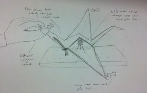
We made an ornamental Origami crane that glows with different colors based on its state. The crane glows red when left alone, and flashes green and blue when its tail is bent in the standard Origami way. We liked this design because it puts multiple forms of interactivity into one design: The crane responds to someone pulling its tail both electronically and mechanically, by both changing color (thanks to the Arduino and Flex sensor) and changing shape (thanks to our Origami design). We think that our design was successful because, as shown in our video, all intended functionality worked. However, the Flex sensor is quite visible and fragile, as it is only taped externally onto the crane’s tail. The design could be improved upon if we had a Flex sensor that was thinner, shorter, and less rigid – ideally, we would use a wire Flex sensor that changed resistance when bent.
III. Diagram:
High-level sketch of our diffuser’s functionality. When someone pulls on the Origami crane’s tail, the Arduino detects the change through the Flex sensor.

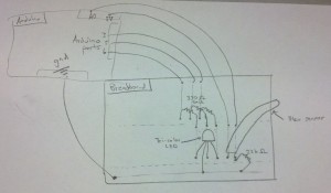
Low-level sketch of how our diffuser is built. Our diffuser is built using a tri-color LED and a Flex sensor, with the LED three prongs each wired to the Arduino’s digital output pins and the Flex sensor wired to one of Arduino’s analog ports.
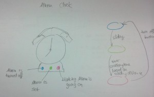
An earlier design we were considering for this project. We gave up on the alarm clock because we thought having a diffusing crane was cooler 🙂

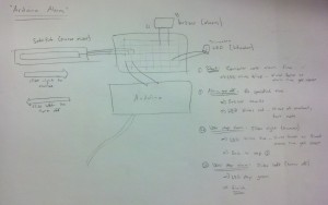
The low level sketch of the earlier design.
IV. Video of final system:
V. Parts used:
- Arduino Uno
- wires
- 22 k ohm resistor
- 3 330 ohm resistors
- flex sensor
- tricolor LED
- wax paper crane
VI. Instructions (see second diagram for more, as well)
- Connect the parts to the Arduino board as shown in the diagram mentioned.
- Connect the ground leg of the tricolor led to ground. Connect each of the other legs to a digital output pin (3, 5, 6) on the Arduino, which one 330 ohm resistor for each leg.
- Connect the positive leg of the flex sensor to 5V, and the other leg to analog in pin A0. Also connect this to a 22 k ohm resistor going to ground.
- Build a paper crane. Stick the LED through the underside of the crane, and tape the flex sensor to the crane’s tail, so that pulling the tail causes both the crane’s wings to move and the flex sensor to register the change in resistance.
VII. Source code
const int ledPinRed = 6;
const int ledPinGreen = 3;
const int ledPinBlue = 5;
int flex = A0;

void setup()
{
  pinMode(ledPinGreen,   OUTPUT);
  pinMode(ledPinRed,   OUTPUT);
  pinMode(ledPinBlue,   OUTPUT);

  digitalWrite(flex, HIGH);
  analogWrite(ledPinRed, 255);
  Serial.begin(9600);
}

void loop() {
  byte brightness = analogRead(flex);
  if (brightness <   50) {
    analogWrite(ledPinRed, 0);
    analogWrite(ledPinBlue, 0);
    analogWrite(ledPinGreen, 255);
    delay(200);
    analogWrite(ledPinGreen, 0);
    analogWrite(ledPinBlue, 255);
  }
  else {
    analogWrite(ledPinGreen, 0);
    analogWrite(ledPinBlue, 0);
    analogWrite(ledPinRed, 255);
  }
  delay(200);
}


