
Group Members
Osman Khwaja
Alejandro Van Zandt-Escobar
Gabriel Chen
Avneesh Sarwate
Prakhar Agarwal
Description
We built a glass world that reacts to light using a photosensor and behaves according to the state it is in. There are three states governed by a button: the idle state, the build state, and the drop state. Before the button is enabled, the world is in a calibration state, used to expose the photoresistor to the range of possible light inputs and thus, resistances. The idle state consists of a tricolor LED, fitted with a straw. The tricolor LED oscillates between all ranges of colors according to three sin functions. The other LEDs do nothing. The build state is to be initiated by the press of the button when the song “Harlem Shake” is played (in light of the recent trend). The tricolor LED begins to change colors erratically, and the remaining LEDs alternate slowly between reds and blues, arranged diagonally from each other. The behavior matches the tempo of the song. The drop state is to be initiated at the beat drop of the song. The tricolor LED continues its erratic behavior, but the remaining LEDs now act based on the light sensor. This can be used to induce extremely erratic behavior all LEDs, in accordance with Harlem Shake tradition. Thus, we felt that our design successfully produced the desired behavior. The different states of the design are a good representation of different stages in the song, and the use of a button allows for ease of state transition. Additionally, the straw and ice cube trays were excellent diffusers, and really emphasized the output of the LEDs. One limitation of our design was the sensitivity of the photoresistor. It was placed under a thick layer of glass, which may have diffused light entering the circuit. Although this made the design more aesthetic, the functionality was slightly impaired. Overall, we were happy with the Harlem Shake video we were able to produce using our design, and we hope that it goes viral!
Photos of Sketches

Follow the finger: Slide sensor controls the brightness of the lights. Lights closest to finger are brightest. Move finger to control the light.
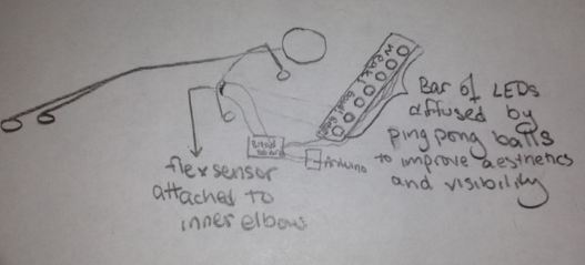
Perfect Pushup: Use a diffuser and flex sensor to determine whether pushup form is correct or not.
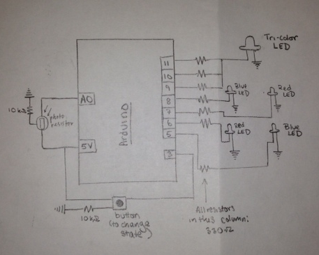
A schematic of our final design.
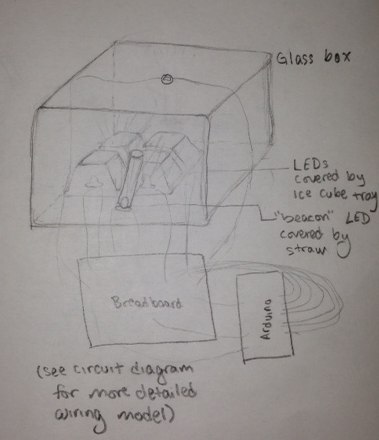
A design diagram of our project.
Video
Parts
- Arduino Uno
- Button
- Photoelectric Sensor
- Ice Cube Tray
- Glass Box/Flower Vase
- 1 Straw
- Wires
- 2 10k Ohm Resistor
- 7 330 Ohm Resistors
- 2 Blue LEDs
- 2 Red LEDs
- 1 Tricolor LED
- 2 Alligator Clips
- Tape
Instructions
- Connect the TriColor LED to the three analog pins 11, 10, 9 through 330 Ohm resistors.
- Connect 4 LEDs in a general box shape just below the TriColor to the pins 7,6,5,4 with a 330 Ohm Resistor for each.
- Attach a photoelectric sensor to the top of the glass box using the alligator clips. Ensure that the sensor is facing outwards.
- Connect the button to the breadboard with the 10k Resistor, pulling 5 Volts from Arduino. Connect the output to pin 3.
- Connect the photosensor with a 10k Resistor to pin A0 on the Arduino.
- Cover the 4 LEDs with the ice cube tray, the tricolor with a straw, and all of them with the glass case.
- When powering up the system, make sure to calibrate the photosensor by covering and uncovering the sensor. The Blue LED will light up during this time.

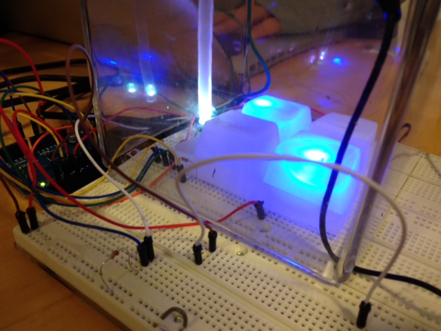
Here is what the final setup should look like.
Source Code
// ----------------------
// Harlem Shake v. 436
// ----------------------
// COS 436, Lab 0
// February 18, 2013
// ----------------------
// Prakhar Agarwal
// Gabriel Chen
// Osman Khwaja
// Avneesh Sarwate
// Alejandro Van Zandt-Escobar
// ----------------------
// The "beacon" (multicolor LED) is connected to three analog outputs
const int beaconRed = 11;
const int beaconGreen = 10;
const int beaconBlue = 9;
// The four other LEDs are connected to four digital outputs
const int ledYellow = 8;
const int ledRed = 7;
const int ledBlue = 6;
const int ledGreen = 5;

// Sensor 1: Photocell
const int sensorPin = A0;

int sensorValue = 0;
int sensorMin = 1023; // minimum sensor value
int sensorMax = 0; // maximum sensor value
int threshold = 127;

// Button
const int buttonPin = 3;

int buttonState = 0; // HIGH or LOW
int buttonCounter = 0; // Number of clicks determines the program's current state.
int lastButtonState = 0; // HIGH or LOW

// Setup Routine
void setup() {

// For debugging:
Serial.begin(9600);

// Set up I/O.
pinMode(beaconRed, OUTPUT);
pinMode(beaconGreen, OUTPUT);
pinMode(beaconBlue, OUTPUT);

pinMode(ledGreen, OUTPUT);
pinMode(ledBlue, OUTPUT);
pinMode(ledRed, OUTPUT);
pinMode(ledYellow, OUTPUT);

pinMode(buttonPin, INPUT);

// Calibrate photocell during the first five seconds.
while (millis() < 5000) { // Light up LED at the beginning of calibration phase. digitalWrite(ledBlue, HIGH); // Read in value from photocell sensorValue = analogRead(sensorPin); // Record the maximum sensor value if (sensorValue > sensorMax) {
sensorMax = sensorValue;
}

// Record the minimum sensor value
if (sensorValue < sensorMin) {
sensorMin = sensorValue;
}

// Turn off LED at end of calibration phase
digitalWrite(ledBlue, LOW);

}

}

// Variables for timing and rhythm
double time = 0;
double t = 0; // Used for sin wave patterns
int beat = 430; // Duration of a beat (in ms)
int downBeatBeacon;
int downBeatCubes;

void loop() {

// *** Process Photocell Input ***
// Read photocell sensor
sensorValue = analogRead(sensorPin);
// Apply calibration
sensorValue = map(sensorValue, sensorMin, sensorMax, 0, 255);
// Map sensor value to desired range
sensorValue = constrain(sensorValue, 0, 255);

// *** Process Button Input ***
// Read state of pushbotton
buttonState = digitalRead(buttonPin);
// Compare the buttonState to its previous state
if (buttonState != lastButtonState) {
// State changes when button is pressed down (from off to on)
// If state has changed then increment counter
if (buttonState == HIGH) {
// If the current state is HIGH then button went from off to on
if (buttonCounter == 2)
buttonCounter = 0;
else
buttonCounter++;
// For debugging:
// Serial.println("on");
// Serial.print("number of button pushes: ");
// Serial.println(buttonCounter);
}
else {
// If the current state is LOW then the button went from on to off
Serial.println("off");
}
}
// save the current state as the last state, for next time through the loop
lastButtonState = buttonState;

// *** Main Program Loop ***

// *** Idle State ***
if (buttonCounter == 0) {
// Tri-color LED has an intersecting sinusoidal pattern
analogWrite(beaconRed, (int) (127 + 127 * sin(t)));
analogWrite(beaconBlue, (int) (127 + 127 * sin(t + 3.14/3)));
analogWrite(beaconGreen, (int) (127 + 127 * sin(t + 6.28/3)));

// Turn all other LEDs off
digitalWrite(ledBlue, LOW);
digitalWrite(ledGreen, LOW);
digitalWrite(ledRed, LOW);
digitalWrite(ledYellow, LOW);

// Progression of sinusoidal pattern
t += 0.1;
delay(20);
}

// *** Build State ***
else if (buttonCounter == 1) {
// Beacon's activity is determined by eighth notes
downBeatBeacon = ((int) (time / (beat / 2)));
// Cube's activity is determined by half notes
downBeatCubes = ((int) (time / (beat * 2))) % 2;

// The beacon plays an accelerated sinusoiodal pattern
// Erratically matched to the rhythm of eighth notes
analogWrite(beaconRed, (int) (127 + 127 * sin(downBeatBeacon + .9)));
analogWrite(beaconBlue, (int) (127 + 127 * sin(9 * downBeatBeacon + .2)));
analogWrite(beaconGreen, (int) (127 + 127 * sin(7 *downBeatBeacon)));

// The four LEDs in the icecube alternate diagonally, on every half beat.
// On beat 1:
if (downBeatCubes == 0) {
digitalWrite(ledBlue, HIGH);
digitalWrite(ledGreen, LOW);
digitalWrite(ledRed, LOW);
digitalWrite(ledYellow, HIGH);
}
// On beat 2:
else if (downBeatCubes == 1) {
digitalWrite(ledBlue, LOW);
digitalWrite(ledGreen, HIGH);
digitalWrite(ledRed, HIGH);
digitalWrite(ledYellow, LOW);
}

// Update every eighth note
delay(beat / 2);
time += beat / 2;

}

// *** Drop State ***
else {
// Beacon's activity is determined by eighth notes
downBeatBeacon = ((int) (time / (beat / 2)));

// The beacon plays an accelerated sinusoiodal pattern
// Erratically matched to the rhythm of eighth notes
analogWrite(beaconRed, (int) (127 + 127 * sin(downBeatBeacon + .9))); // turn the LED on (HIGH is the voltage level)
analogWrite(beaconBlue, (int) (127 + 127 * sin(9 * downBeatBeacon + .2))); // turn the LED on (HIGH is the voltage level)
analogWrite(beaconGreen, (int) (127 + 127 * sin(7 *downBeatBeacon)));

// The cube LEDs play the same pattern, but switch according
// to input from the photocell.
if (sensorValue < threshold) {
digitalWrite(ledBlue, HIGH);
digitalWrite(ledGreen, LOW);
digitalWrite(ledRed, LOW);
digitalWrite(ledYellow, HIGH);
}
else {
digitalWrite(ledBlue, LOW);
digitalWrite(ledGreen, HIGH);
digitalWrite(ledRed, HIGH);
digitalWrite(ledYellow, LOW);
}

// Update every eighth note
delay(beat / 2);
time += beat / 2;
}
}