
Group 10:
- Junjun Chen (junjunc),
- Igor Zabukovec (iz),
- (av),
- Osman Khwaja (okhwaja).
Description:
This DigiSketch is intend to do renew the famous Etch-a-Sketch, providing a new way to write on the computer. The principle is quite simple : use the two potentiometers to draw lines of circles and the photo-sensor to change the color of them. You can basically write and draw whatever you want. Start by writing letters, basic forms, and continue by increasing the complexity of your drawings and to test how skillful you are, try to draw a circle. If the user is adventurous, the Processing program can be modified in order to use a different color palette, a different sized canvas, or a different pen shape.
Our system overall achieved its goal. However, the calibration of the photocell could be improved, in order to allow the user more precise control over the color. Perhaps a different sensor could be used for this purpose. To make the system more sophisticated, we could have three different sensors controlling red/green/blue, rather than a single sensor controlling the shade of one color, as we have now. In general, our system proves how easy it is to replicate the Etch-a-Sketch concept; the possibilities for refinement are vast.
Photos of sketches:
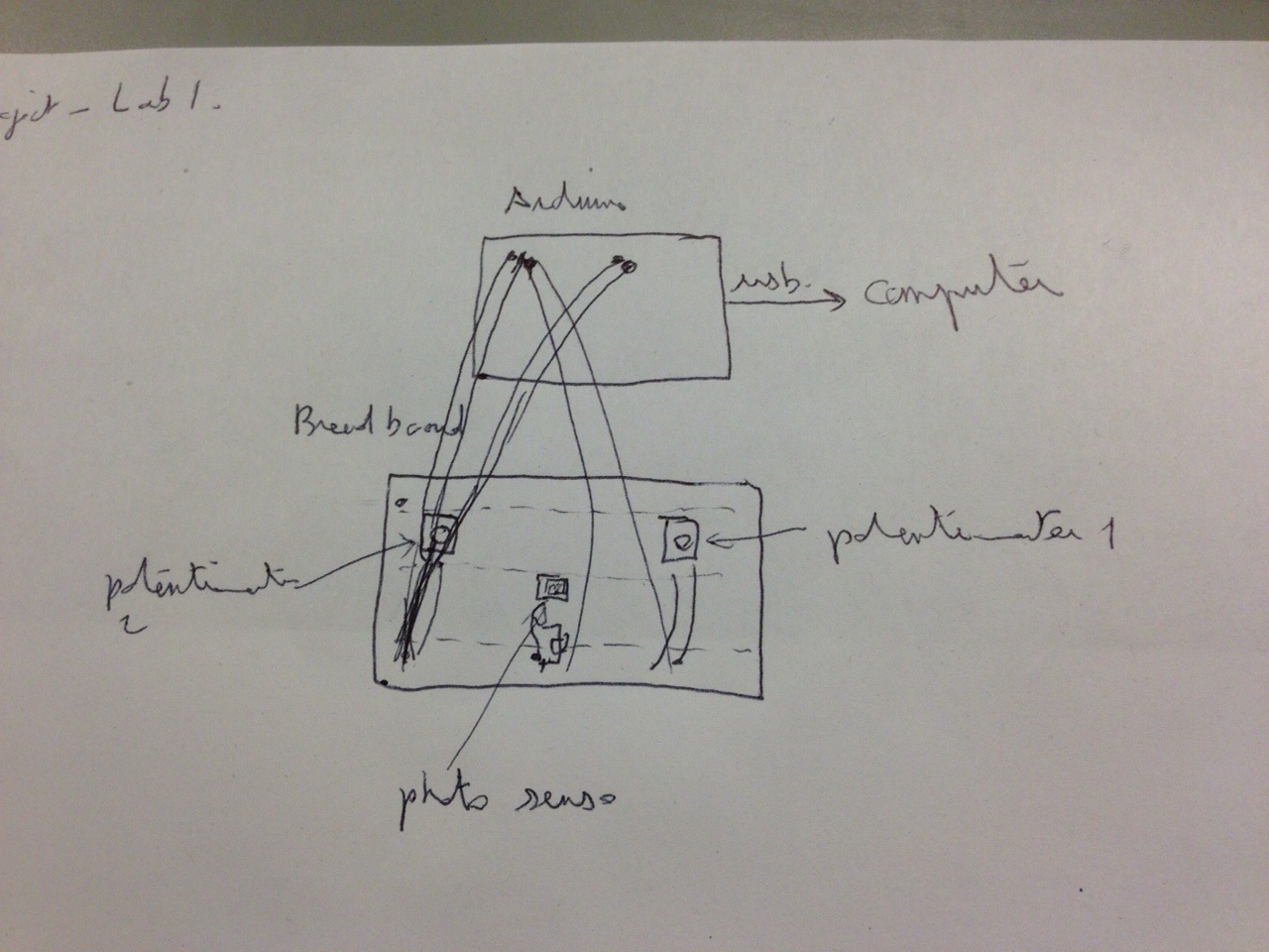
A system which allows you to draw in Processing using two rotary potentiometers to control position, and using a photocell to control color.
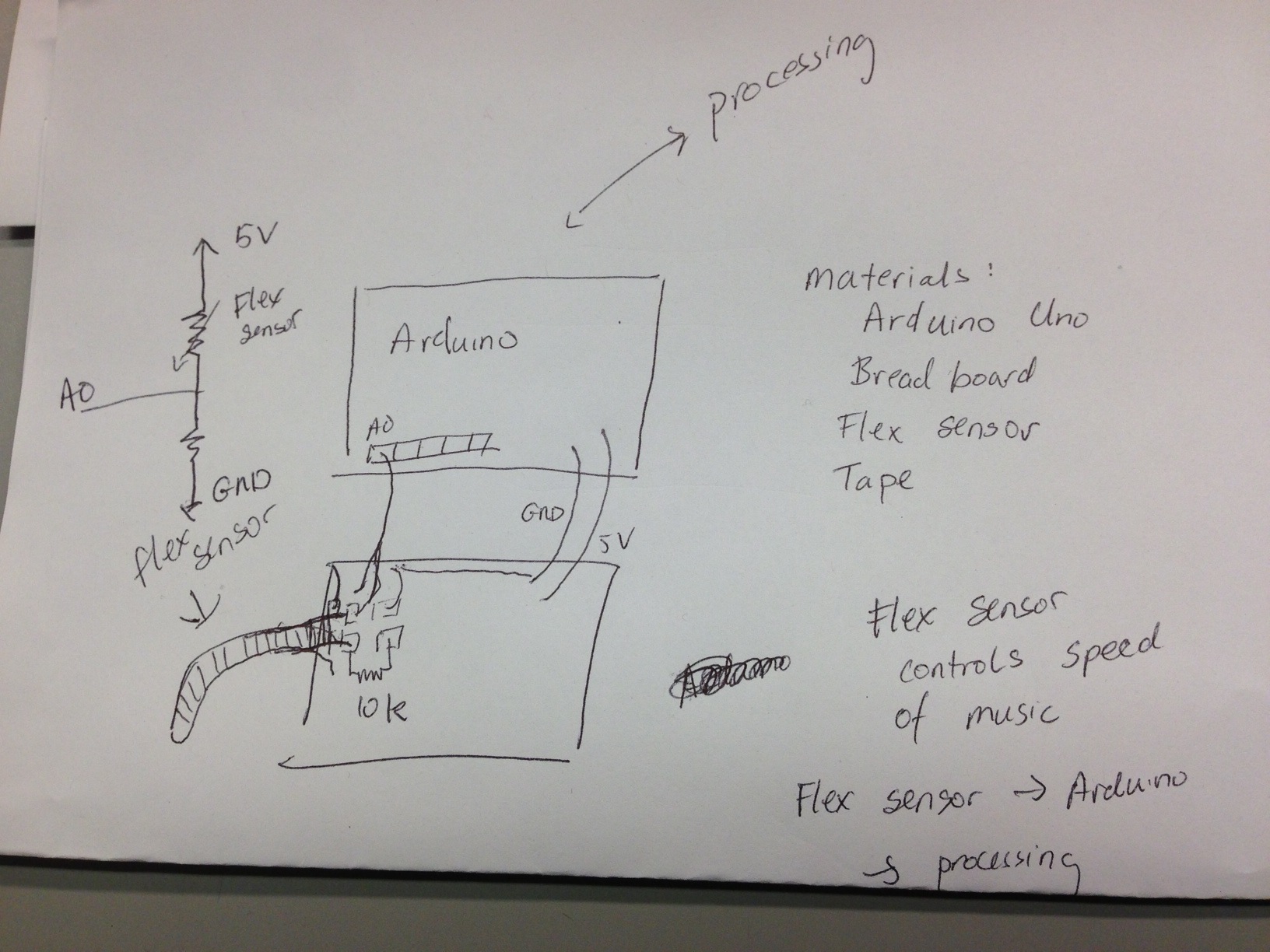
A system which allows you to control the playback speed of a sound file by flexing your finger.
An LED night-light system: turns on the night light when it is dark.

Storyboard: 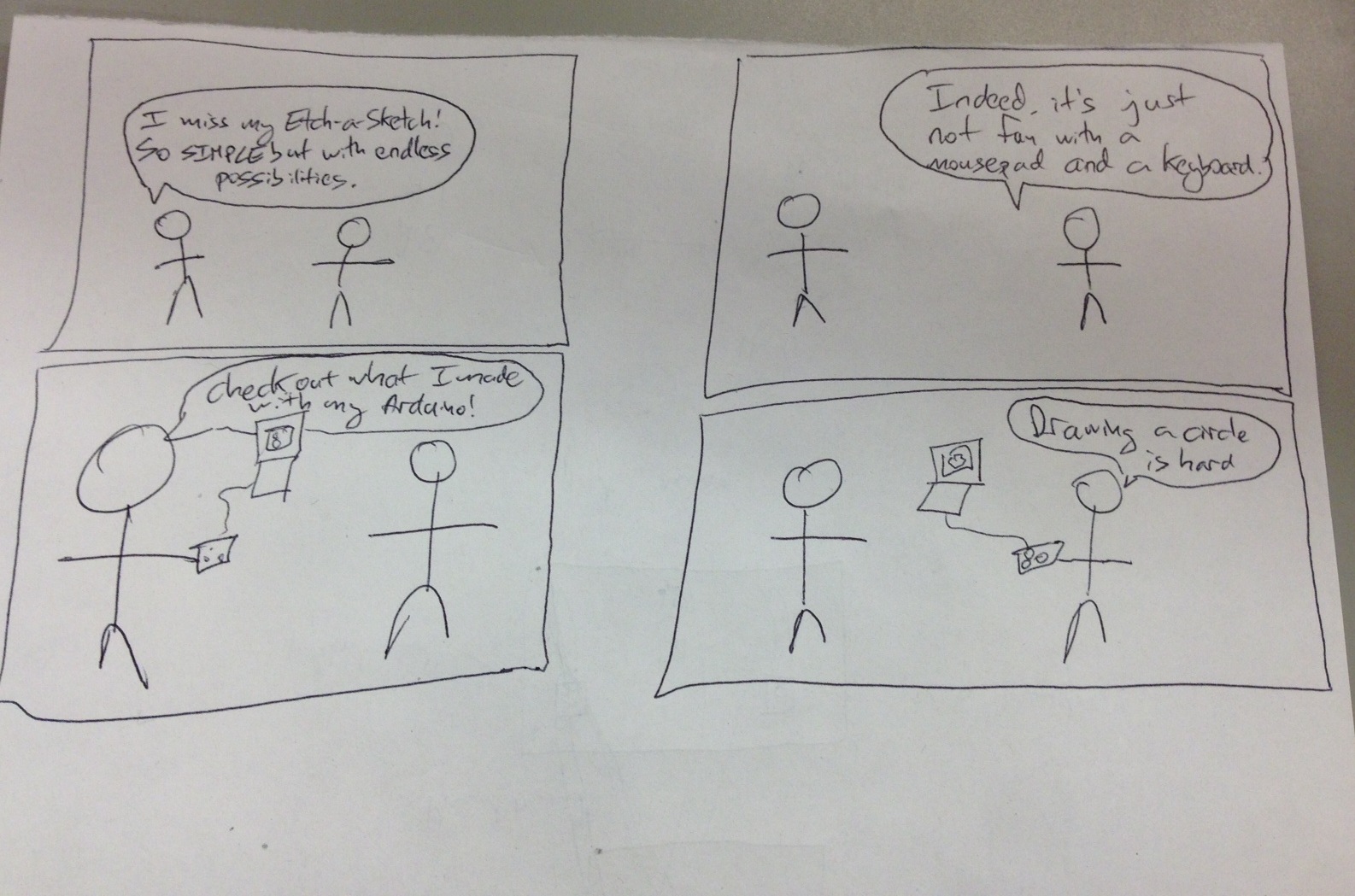
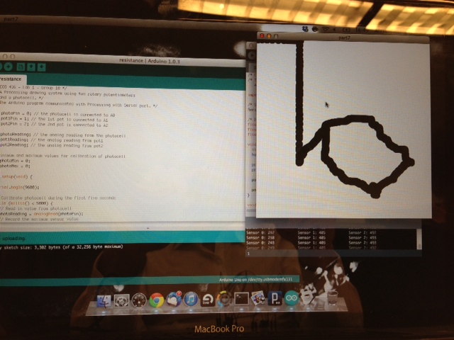
DigiSketch in Action:
The Arduino and the circuit:

An example of different colors that can be obtained by varying input to the photocell:
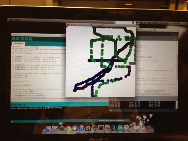
An attempt at drawing a circle:
List of parts
- Arduino, wires, USB cord, breadboard
- 10 k ohm resistor
- Photocell
- 2 rotary pots
Instructions for Recreation
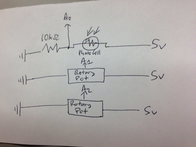
Connect a photocell to the bread board, with a 10kOhm pull down resistor from one leg of the photocell the ground. Connect the other leg to 5V. Connect the point between the photocell and the resistor to analog pin on the Arduino (we used A0). Connect a rotary potentiometer the the breadboard so that one other pin is connected to 5V and the other outer pin is connected to ground. Connect the middle pin to another analog pin (A1). Do the same for the other rotary pot to connect it to A2. Use the attached source code for Processing and Arduino – the Processing program receives messages from Arduino in order to draw on the screen.
Circuit diagram:
Arduino Source Code:
/* COS 436 - Lab 1 - Group 10 */
/* A Processing drawing system using two rotary potentiometers
   and a photocell. */
/* The Arduino program communicates with Processing with Serial port. */

int photoPin = 0; // the photocell is connected to A0
int pot1Pin = 1; // the 1st pot is connected to A1
int pot2Pin = 2; // the 2nd pot is connected to A2

int photoReading; // the analog reading from the photocell
int pot1Reading; // the analog reading from pot1
int pot2Reading; // the analog reading from pot2

// minimum and maximum values for calibration of photocell
int photoMin = 0;
int photoMax = 0;

void setup(void) {

  Serial.begin(9600);

  // Calibrate photocell during the first five seconds
  while (millis() < 5000) {     // Read in value from photocell     photoReading = analogRead(photoPin);     // Record the maximum sensor value     if (photoReading > photoMax) {
      photoMax = photoReading;
    }
    // Record the minimum sensor value
    if (photoReading < photoMin) {       photoMin = photoReading;     }   }      // Establish contact with Processing   establishContact(); } void loop(void) {   // Only send messages when there is a connection   if (Serial.available() > 0) {
    // Read input from Arduino's analog pins
    photoReading = analogRead(photoPin);
    pot1Reading = analogRead(pot1Pin);
    pot2Reading = analogRead(pot2Pin);

    // Map sensor value to desired range
    photoReading = map(photoReading, photoMin, photoMax, 0, 255);
    photoReading = constrain(photoReading, 0, 255);

    // Send sensor reading as comma separated values.
    Serial.print(photoReading);
    Serial.print(",");
    Serial.print(pot1Reading);
    Serial.print(",");
    Serial.println(pot2Reading);
  }
}

// Establish contact with processing.
void establishContact() {
  // Send an initial string until connection made
  while (Serial.available() <= 0) {
    Serial.println("0,0,0");
    delay(300);
  }
}
/* COS 436 - Lab 1 - Group 10 */
/* The Processing program recieves input from sensors which the
   Arduino sends by serial port. */

import processing.serial.* ;

/* Serial port for message communication. */
Serial port;

/* Drawing parameters */
float ypos;
float xpos;
float fgcolor;

void setup() {
  size(500, 500); /* Canvas dimensions */
  background(255); /* White background. */

  println("Available serial ports:");
  println(Serial.list());

  port = new Serial(this, Serial.list()[0], 9600);

  port.bufferUntil('\n'); /* Read in one line at a time. */
}

void draw() {
  fill(fgcolor, fgcolor, fgcolor); /* Set color. */
  ellipse(xpos, ypos, 20, 20); /* Draw circle with a center determined by pots. */
}

void serialEvent(Serial port) {
  String myString = port.readStringUntil('\n'); /* Read in a line. */
  myString = trim(myString); /* Remove leading / tailing whitespace. */

  int sensors[] = int(split(myString, ',')); /* Split CSV input into int array. */

  // Print out sensor values:
  for (int sensorNum = 0; sensorNum < sensors.length; sensorNum++) {     print("Sensor " + sensorNum + ": " + sensors[sensorNum] + "\t");   }   println();      if (sensors.length > 1) { /* else input is incorrectly formatted */
    fgcolor = 255 - sensors[0]; /* Set color of circles */
    xpos = map(sensors[1], 0, 1023, 0, width); /* Set x-position of circle center. */
    ypos = map(sensors[2], 0, 1023, 0, height); /* Set y-position of circle center. */
  }
  port.write("A"); // Send byte to get more data from Arduino program.
}