
Andrew Ferg
Bereket Abraham
Lauren Berdick
Ryan Soussan
Our project:
We built a “joystick” controller which, when employed, controlled the movement of a 3D box on the screen. The joystick is made up of two rotary potentiometers. The potentiometers were used to rotate the cube in the y and z direction. One potentiometer controls the y direction, the other in the z. At first, we tried to add in a thin pot sensor to move the box up and down. However, the thin pot was not cooperating with the system and its readings were being affected by the readings of the potentiometer. We had to take this out of the system, because it was causing unexpected movement. Despite this, overall, we believe the project was quite successful. We were able to get rid of jerkiness in the image, so it was a smooth fluid motion and rotation. There was a problem with oversensitivity due to small fluctuations but we were able to fix that. Therefore, given time, we believe this could be made into a reasonable interactive interface. This has AutoCAD applications. 3D designs can be rotated and fully examined with easy movement. 3D images of buildings, monuments, molecules, etc (the opposite of 360 degree camera tours) can be viewed from all angles (e.g. for educational purposes or tours). It could be extended to control, instead of a box, for example a 3D model of a car as a game, or other objects.
Sketches:
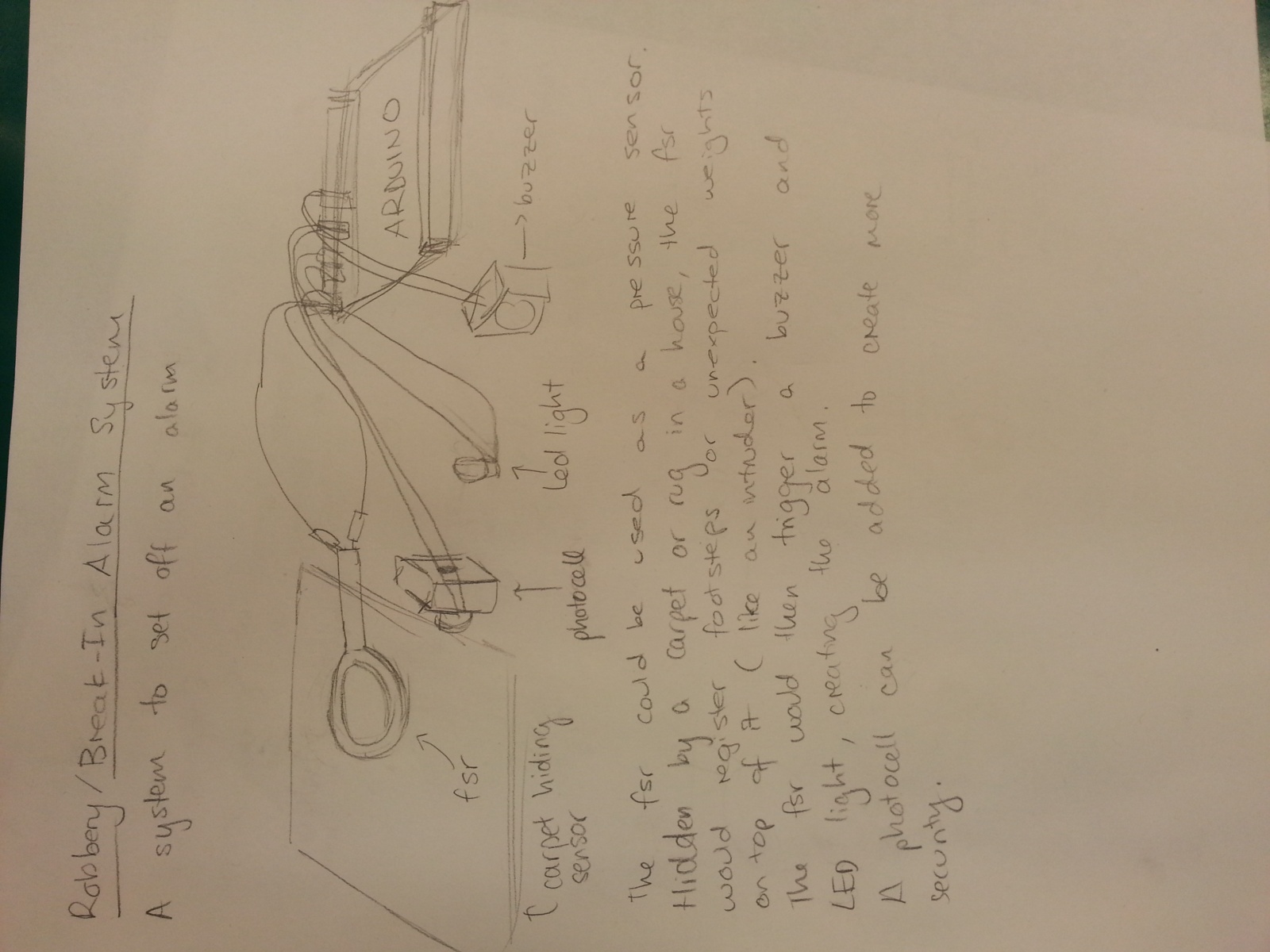
An alarm system which uses an fsr and a photocell to detect unexpected motion to set off a buzzer and LED light as an alarm.
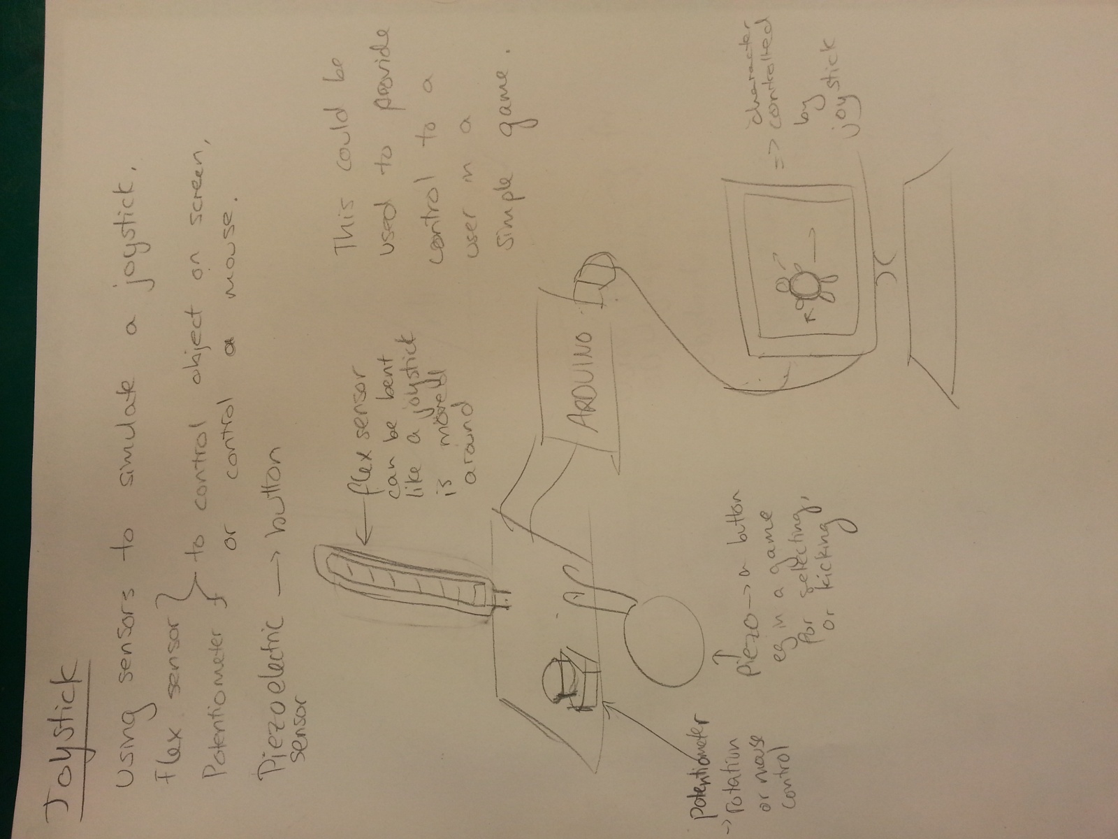
Joystick using flex sensor and potentiometer

Uses a potentiometer to rotate a graphic. Input from sensors go through to Processing.
Storyboard:
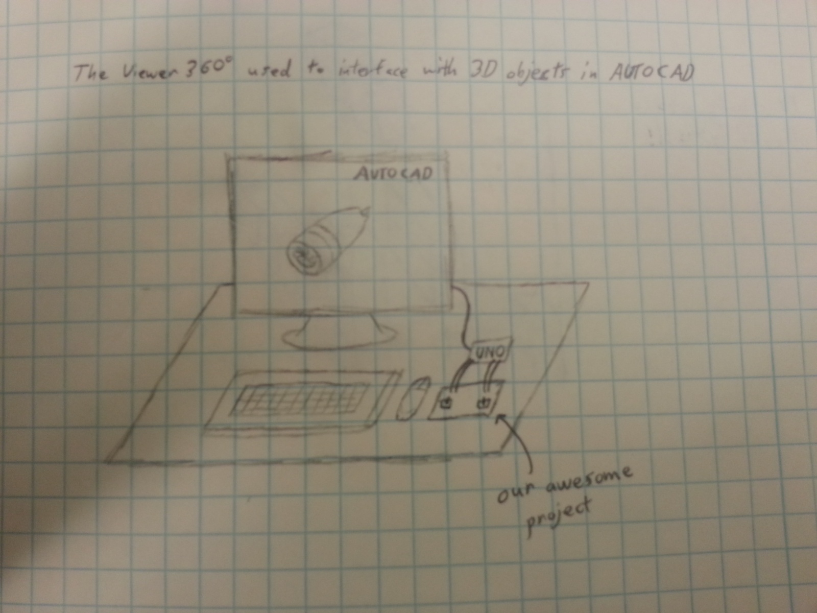
Can be used for AutoCAD purposes.
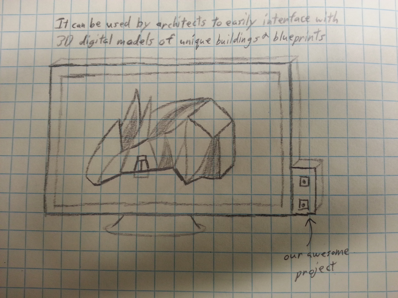
Can be used to examine ideas for building design.

Can be used for 3D gaming purposes, e.g. making tetris more intense in 3D.
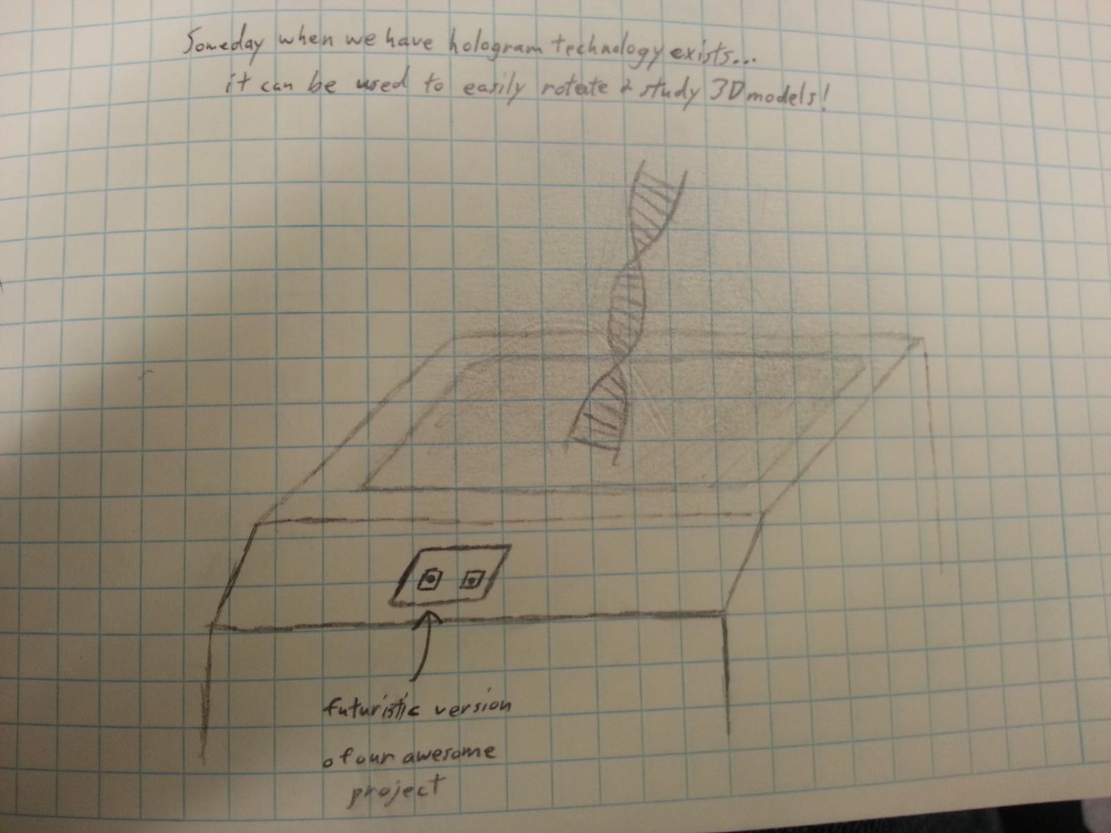
Can be used for educational purposes. For example viewing DNA molecules; the 3D graphics and rotating manipulation allows 360 degrees of examination and studying.
Final system:
Video uploaded on youtube at:
http://www.youtube.com/watch?v=WnXExTsq5nc&feature=youtu.be
Parts used:
– 2 potentiometers
– 1 arduino board
– 8 Wires
– 1 breadboard
To recreate the design:
To build the 3d Viewer, we used two potentiometers with the arduino and fed values to processing. We brought 5V and ground to a breadboard from the arduino, and fed those values to each potentiometer. The potentiometers were wired the same – we put 5V on the pin on side ‘3’ of the potentiometer, wired an analog pin from the ardiuno to the middle pin of each potentiometer (using analog pins 0 for one and 1 for the other), and wired the ground to the ‘1’ side of each pot. In all we used — jumper cables between the breadboard and arduino. When we turn the pot, the analog inputs change on the arduino. The potentiometers each had full values of 10k Ohms. To summarize the code, we fetched values from the analog inputs and then converted these values (stored initially as integers) to bytes, and sent them to processing through our ardiuno and computer using a usb cord. Processing then scaled the value of each pin to a number between 0 and 2pi, and these values determined the rotation of the 3d object. We chose to rotate the object about the y and z axes, and both can be done at the same time. This provides the user with the ability to view every part of the 3d object, and rotate it to preferred positions.
Source Code:
//ARDUINO CODE
<pre>
/* FSR simple testing sketch.
Connect one end of FSR to power, the other end to Analog 0.
Then connect one end of a 10K resistor from Analog 0 to ground
For more information see www.ladyada.net/learn/sensors/fsr.html */
int fsrPin = 0;
int fsrReading;
int scndPin = 1;
int scndReading;
byte fsrByte;
byte scndByte;
// the FSR and 10K pulldown are connected to a0
// the analog reading from the FSR resistor divider
void setup() {
// We’ll send debugging information via the Serial monitor
Serial.begin(9600);
}
void loop() {
fsrReading = analogRead(fsrPin);
scndReading = analogRead(scndPin);
fsrReading /= 4;
scndReading /= 4;
fsrByte = (byte)fsrReading;
scndByte = (byte)scndReading;
Serial.write(fsrByte);
Serial.write(scndByte);
// the raw analog reading
delay(100);
}
</pre>
<pre>
//PROCESSING CODE
import processing.serial.*;
float alpha;
float theta;
float alphaN;
float thetaN;
Serial port;
void setup_port() {
port = new Serial(this, Serial.list()[4], 9600);
}
void setup() {
size(500,500,P3D);
alpha = 0.0;
theta = 0.0;
alphaN = 0.0;
thetaN= 0.0;
setup_port();
}
void draw() {
background(255);
stroke(0);
fill(175);
while (port.available() <2) { };
if (port.available() > 0) {
thetaN = port.read();
alphaN = port.read();
thetaN *= 0.02463994238;
alphaN *= 0.02463994238;
if (abs(thetaN – theta) > .2) {
theta = thetaN; }
if (abs(alphaN – alpha) > .2) {
alpha = alphaN; }
}
translate(250, 250); //translate the coordinates
rotateX(theta); //rotate Z first
rotateY(alpha); //rotate y then
box(200); //draw an ugly box
}
//void keyPressed() {
// if (key == ‘w’) {
// theta += .1;
// }
// if (key == ‘s’) {
// theta -= .1;
// }
// if (key == ‘a’) {
// alpha -= .1;
// }
// if (key == ‘d’) {
// alpha += .1;
// }
// if (key == ‘i’) {
// y -= 5;
// }
// if (key == ‘k’) {
// y += 5;
// }
//}
</pre>