
Team #7
John O’Neill: jconeill@
David Lackey: dlackey@
Horia Radoi: hradoi@
Project Description
Our main project aimed to create a pointer device which enables the user to obtain a different sound based on the position of the nozzle of the gun – a musical uzi, or, as we have affectionally called it, The Muuzi. The idea came to us after we saw initial P1 brainstorm. We decided to use the accelerometer to determine the position of the gun’s x orientation, which we mapped to a range of pitches using an Arduino mapping function. The range we chose to map to was found via trial an hour; the one we settled one was the most relatively desirable, and thus, consider this version of the project to be a success. We managed to solve an issue with our intervals by performing integer division and multiplication (in order to normalize the intervals and avoid having two different noises being played at the same position.) In the future, we might expand the project to a 2- or 3-dimensional space.
Materials
- 1 One Plastic Gun
- 1 Accelerometer
- 1 Arduino
- 1 Piezo Sensor
- 1 Breadboard
Instructions
First, place the breadboard on one side of the plastic gun and the Arduino on the opposing side. Orient and attach the accelerometer as it appears in the included photos so that any movements of the gun will correspond correctly with the provided code. Next, wire it such that the ground pin leads to A2, the power pin leads to A5, and the x-axis pin leads to A5. Now add the buzzer to pin 8, the Piezo sensor to A3, and complete the rest of the circuit as demonstrated in the accompanying photos.
Videos
Pictures
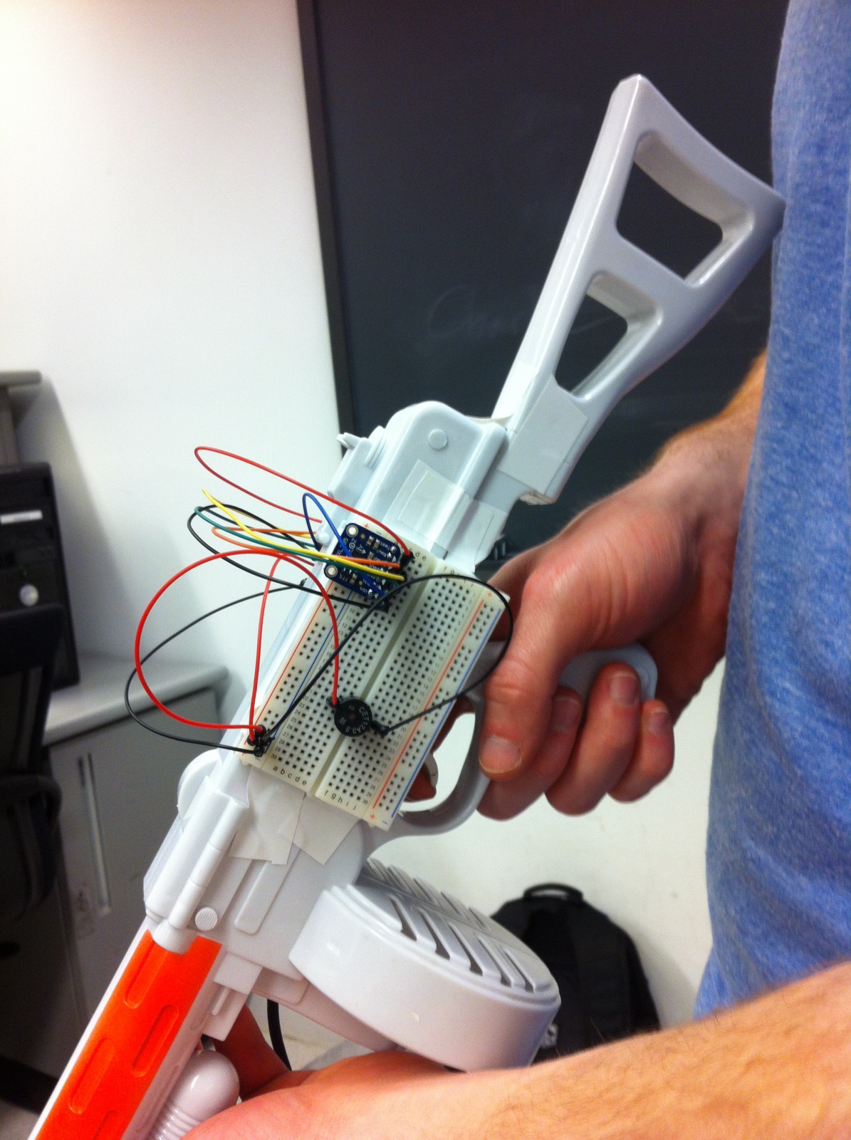
The breadboard, featuring the accelerometer and the buzzer.
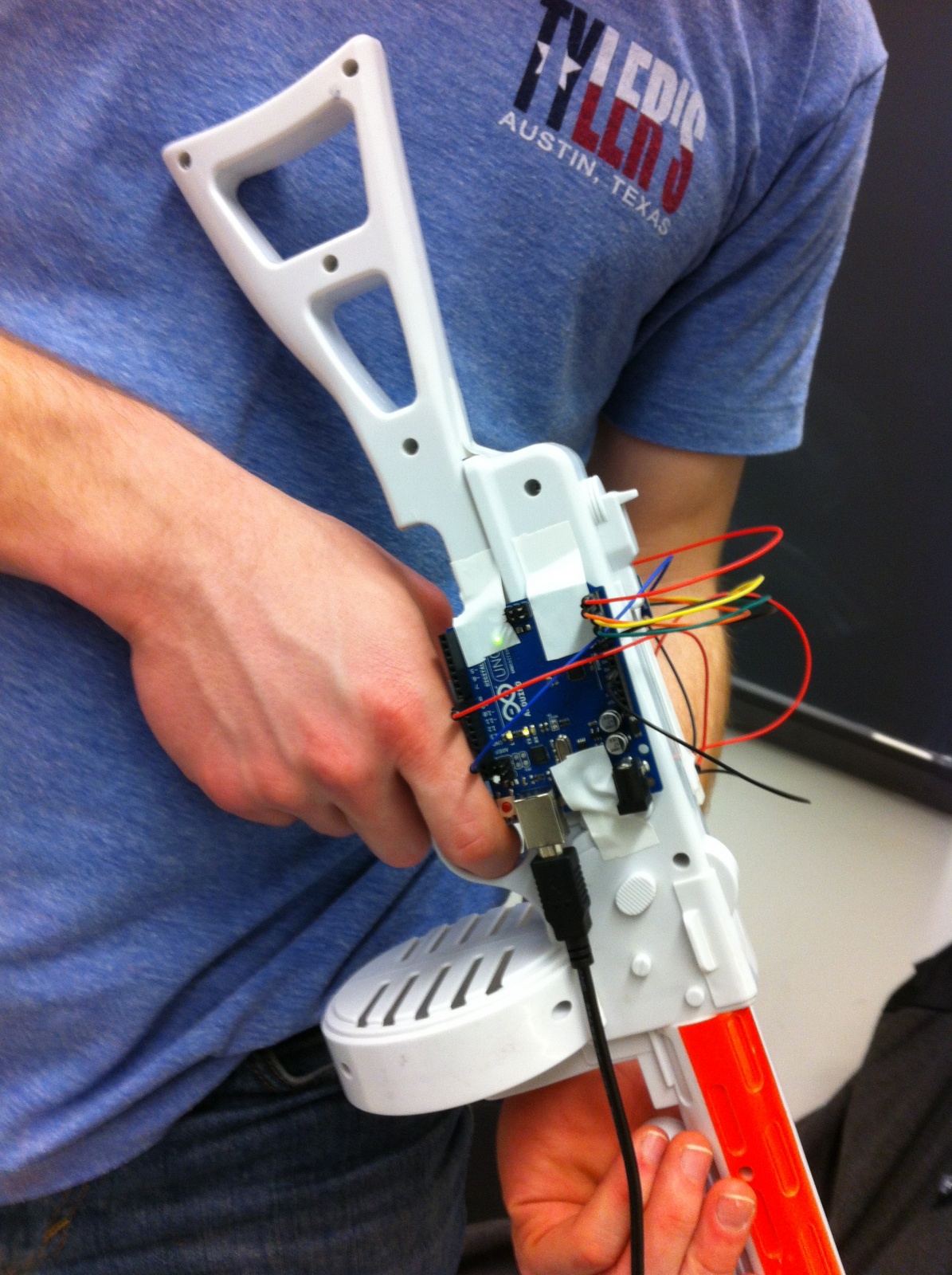
The Arduino, attached to our musical uzi.
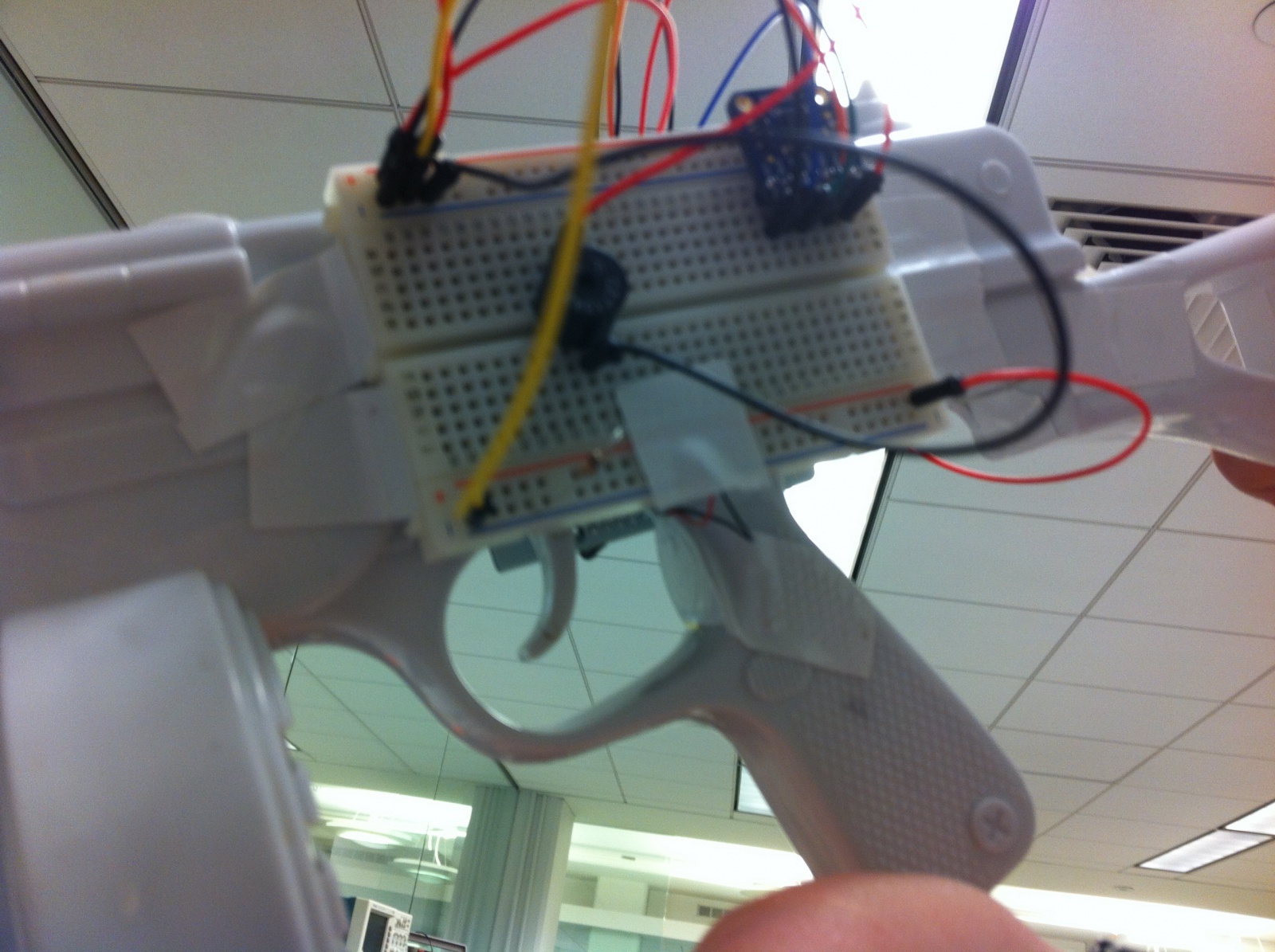
A close-up view of the Piezo sensor, located behind the actual trigger (since the actual one generates a noise itself.)
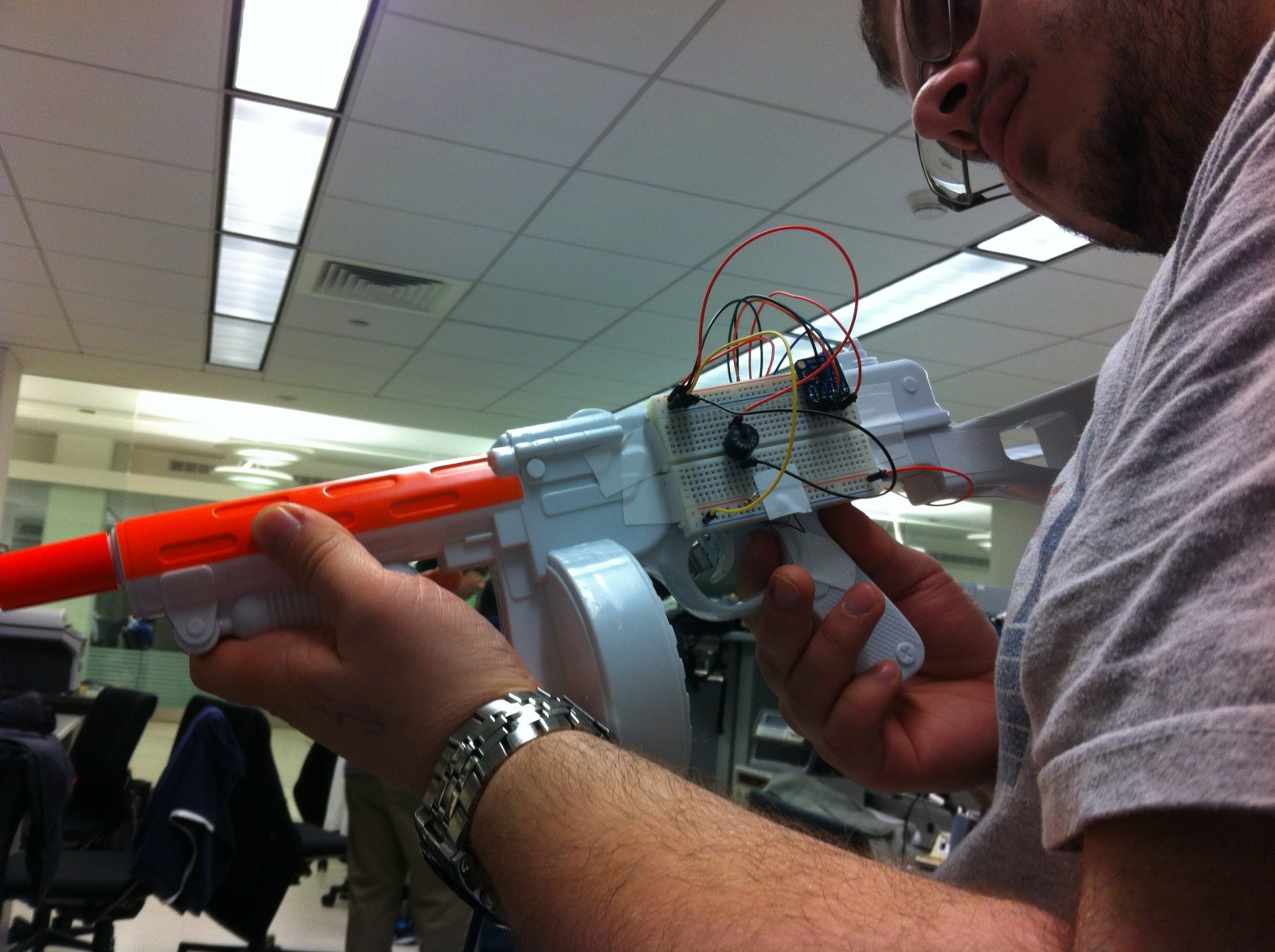
A user testing the Piezo sensor as a firing mechanism.
Source Code
const int groundpin = A2; // analog input pin 2
const int powerpin = A0; // analog input pin 0
const int xpin = A5; // x-axis
const int xmin = 396;
const int xmax = 620;

void setup()
{
 // initialize the serial communications:
 Serial.begin(9600);

 // Provide ground and power by using the analog inputs as normal
 // digital pins. This makes it possible to directly connect the
 // breakout board to the Arduino. If you use the normal 5V and
 // GND pins on the Arduino, you can remove these lines.
 pinMode(groundpin, OUTPUT);
 pinMode(powerpin, OUTPUT);

 digitalWrite(groundpin, LOW);
 digitalWrite(powerpin, HIGH);
}

void loop()
{
 int val = 0;
 int xreading = analogRead(xpin);
 // if the gun is pointed downward
 if ((xreading - xmin) < 20) {
   val = 0;
 }
 else {
   val = map(xreading, xmin, xmax, 1000, 5000);
   val = val / 500;
   val = val * 500;  //make values more discrete
 }
 int x = analogRead(A3);  // read in sensor behind trigger
 if (x > 10)
   tone(8, val, 1000);
 delay(100);
}
Prototype #1: Slide Machine
This project created a music instrument in which the pitch varies according to a resistive slider. It succeeded in making the pitch vary by using a slider. It involved an led which lights up according to the power put up by the pwm. But because it was pointless, we did not include it in the final version.
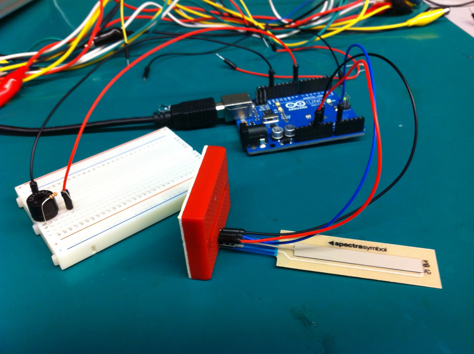
Mapping a slide sensor to different pitches.
Prototype #2: Holy Tones
This prototype used two photocells, as well as a custom-made box which two holes, which allowed us greater control over the light that the sensors encountered. We built it as a way of developing a non-contact musical instrument, and found it moderately successful.
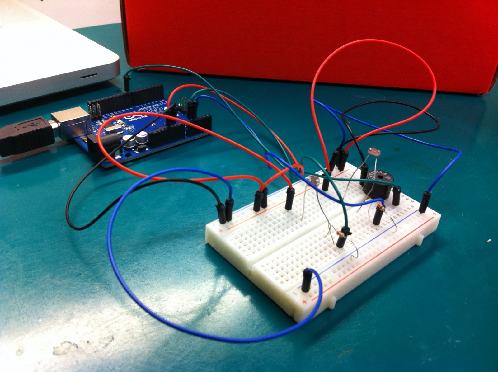
The base of our prototype, which houses two photocell sensors.
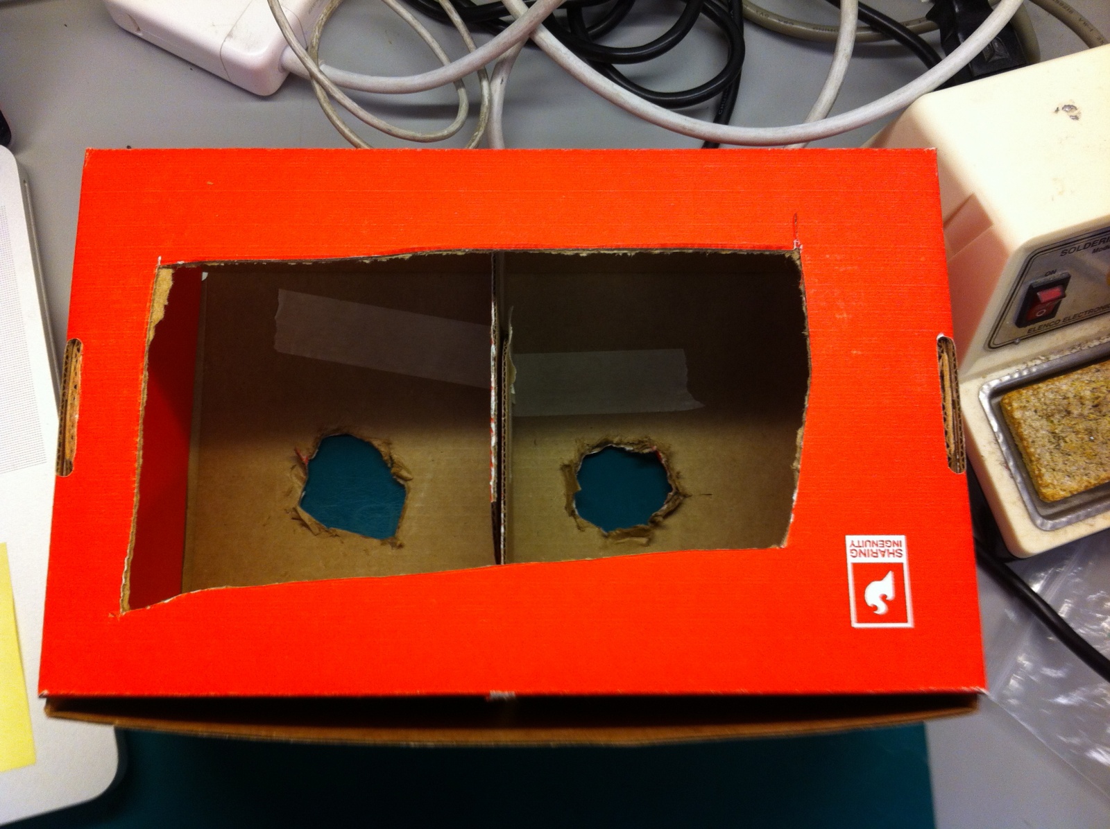
The box that went over our breadboard, which had a divider to help isolate the light on each side.