Lab1

Group Members: Matthew Drabick, Adam Suczewski, Andrew Callahan, Peter Grabowski

High Level Description:

Access to inexpensive, portable medical equipment is a serious problem in many developing countries. There are currently solutions available, but many ignore the diagnosis of neurodegenerative disorders. We aim to provide a compact, easy to use package to aid in the diagnosis of such diseases using 3 basic tests.

First, our diagnostic suite includes a spirometer to measure lung capacity and expulsion rate. This is an important metric, for shortness of breath can be an indication of increased brain pressure, stroke, or tumors (Shortness of Breath).

Second, our diagnostic suite includes a measure of reaction time. Many patients with Parkinson’s disease have difficulty initiating movement, and as a result exhibit an increase in reaction time (Movement Disorders). This test can help diagnose some of those cases.

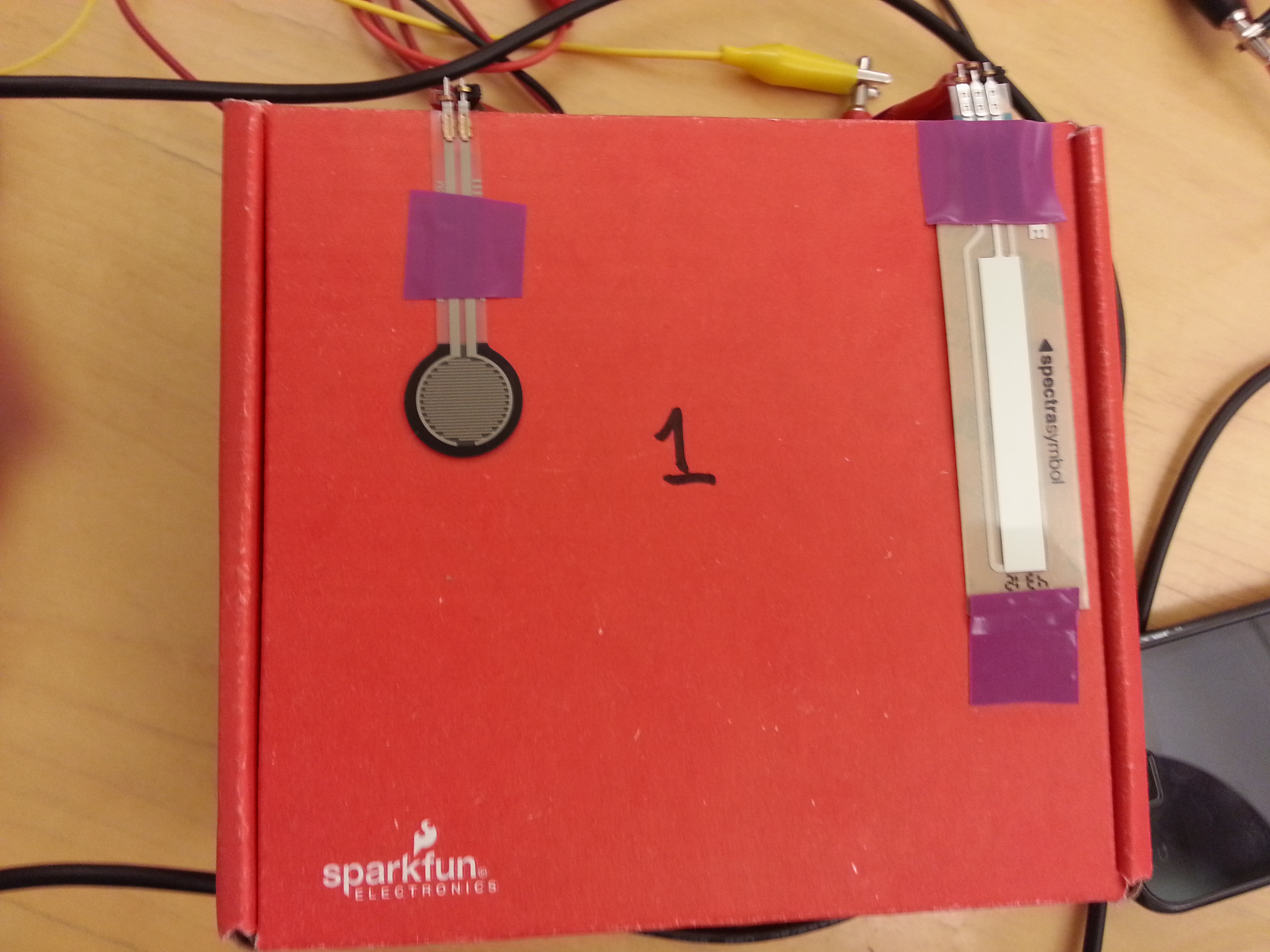
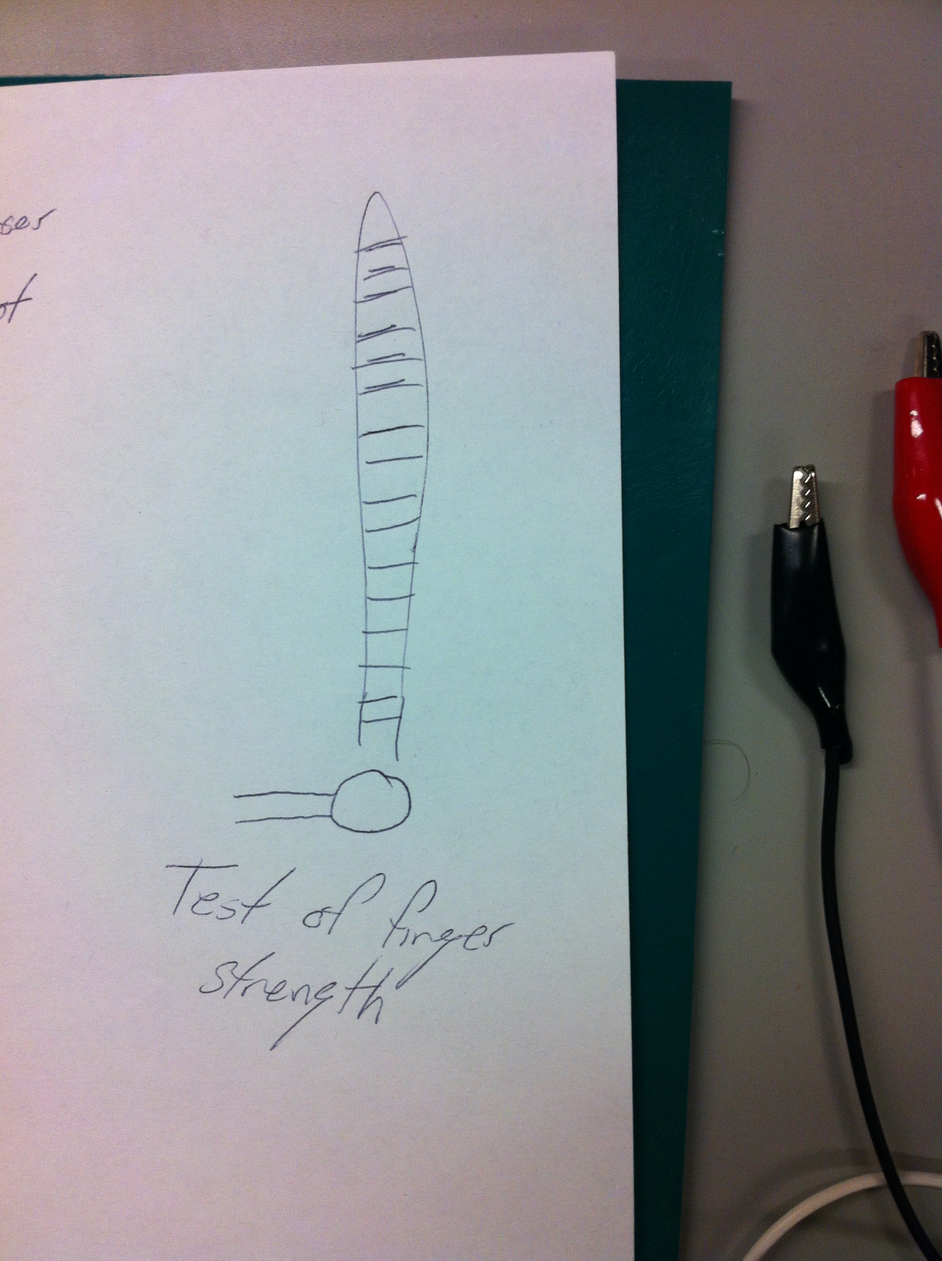
Third, our diagnostic suite includes a digital strength test. Difficulty with finger movements or strength can be an indicator of polyneuropathy (Physical Examination). Our strength test attempts to give a more honest evaluation of finger strength.

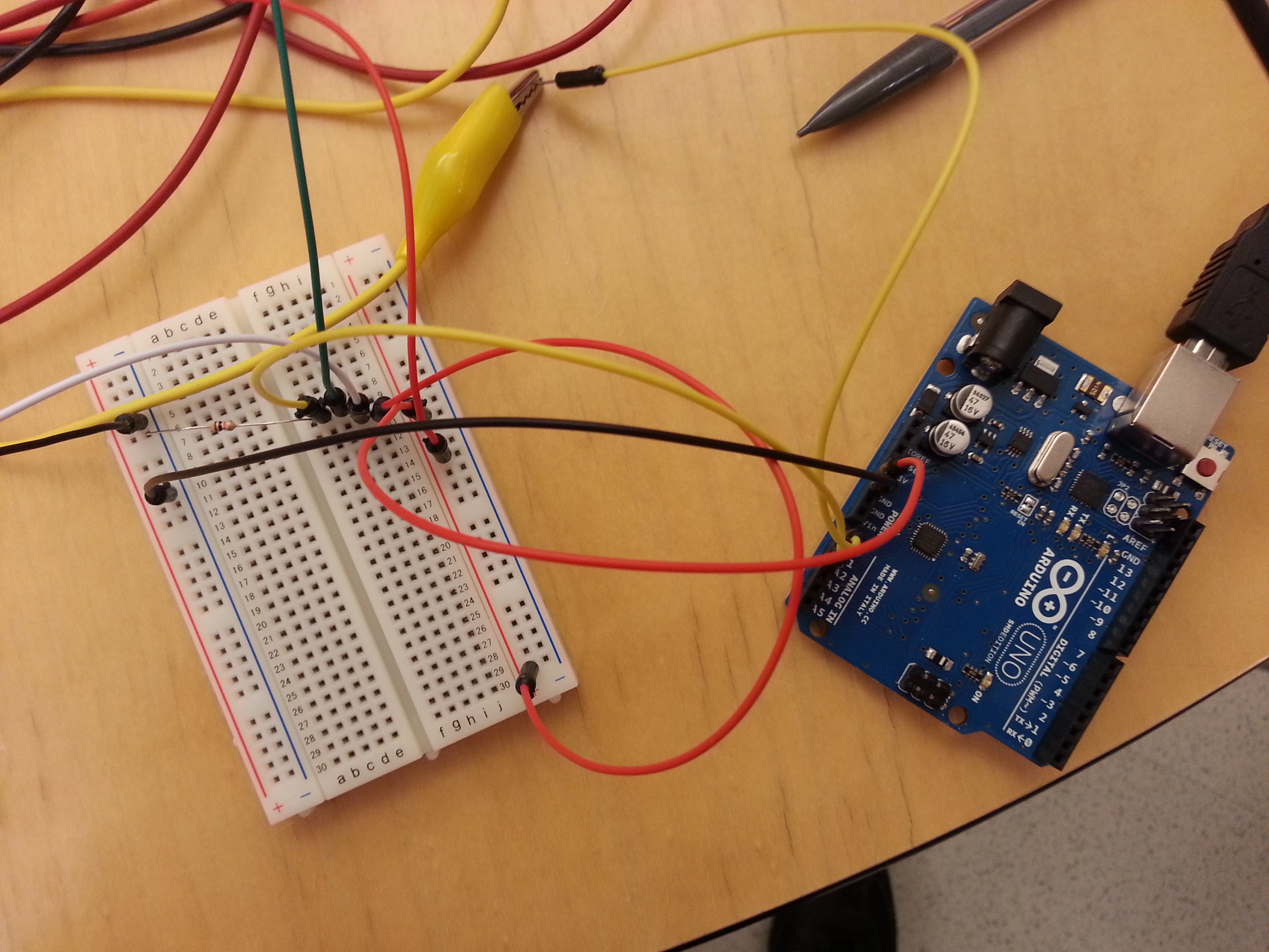
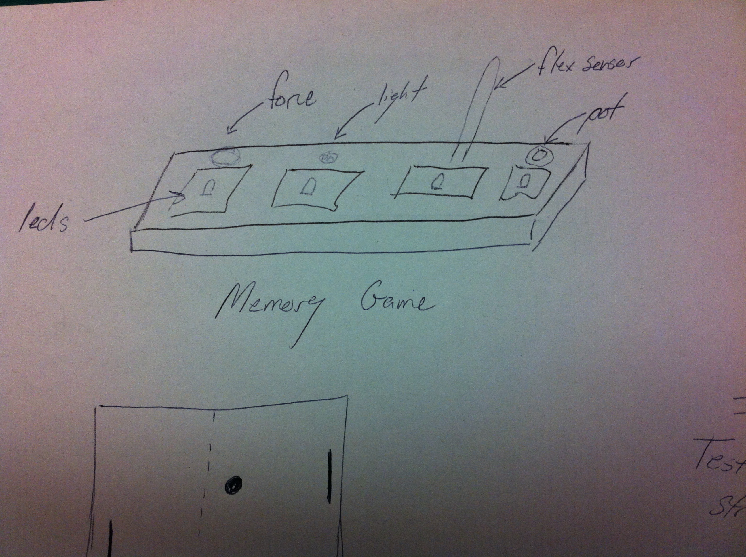
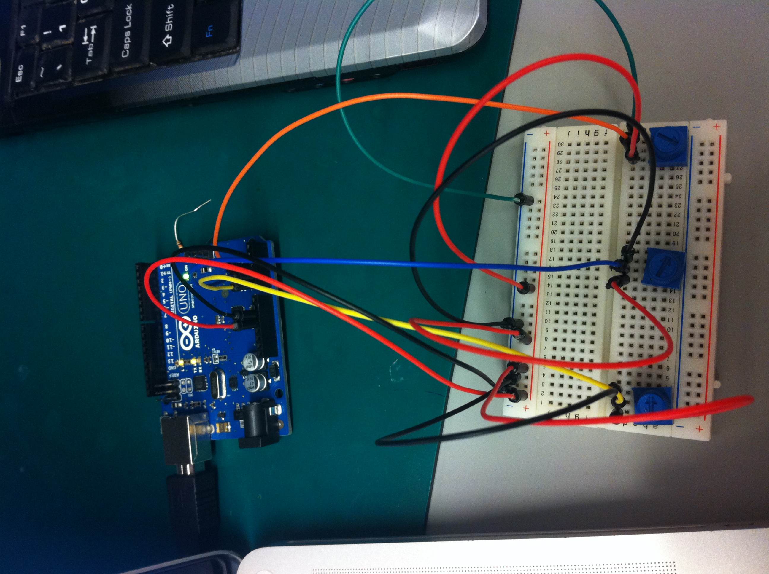
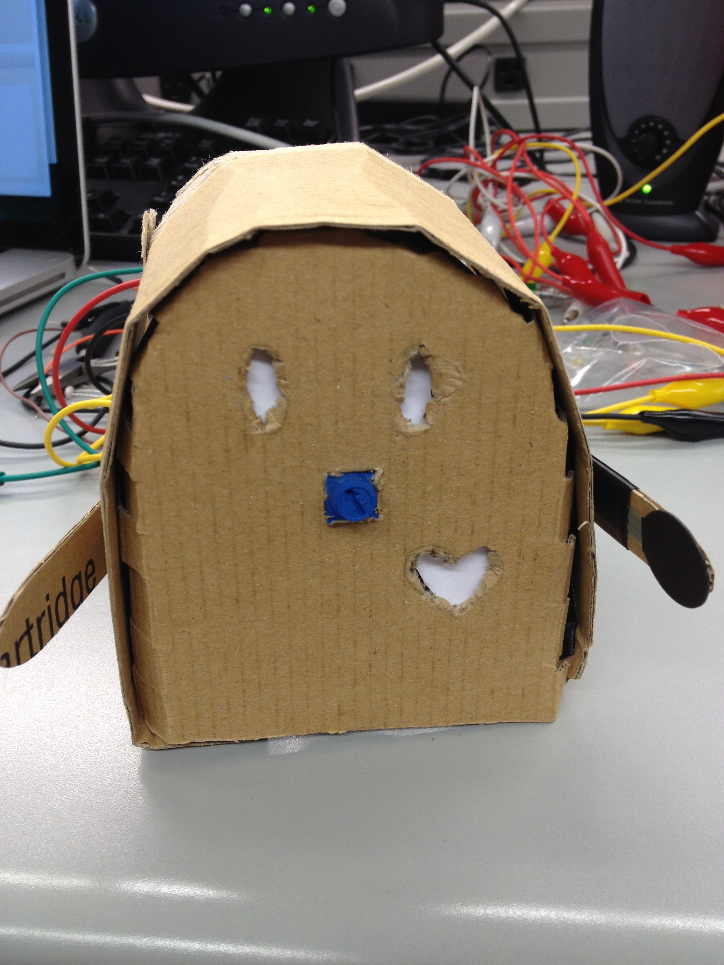
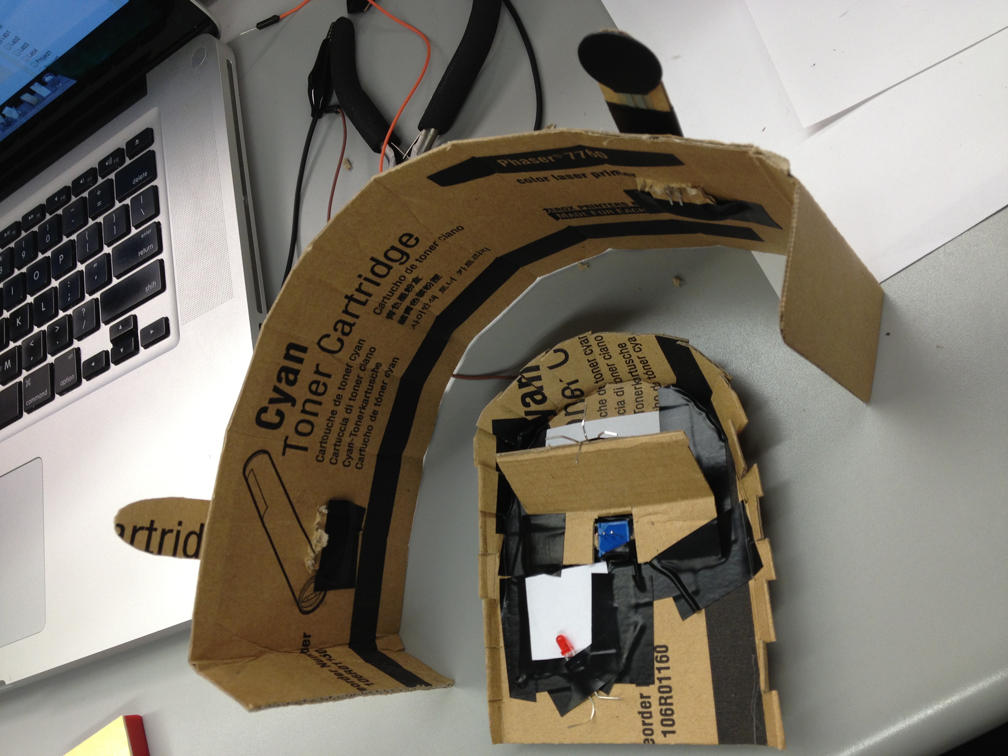
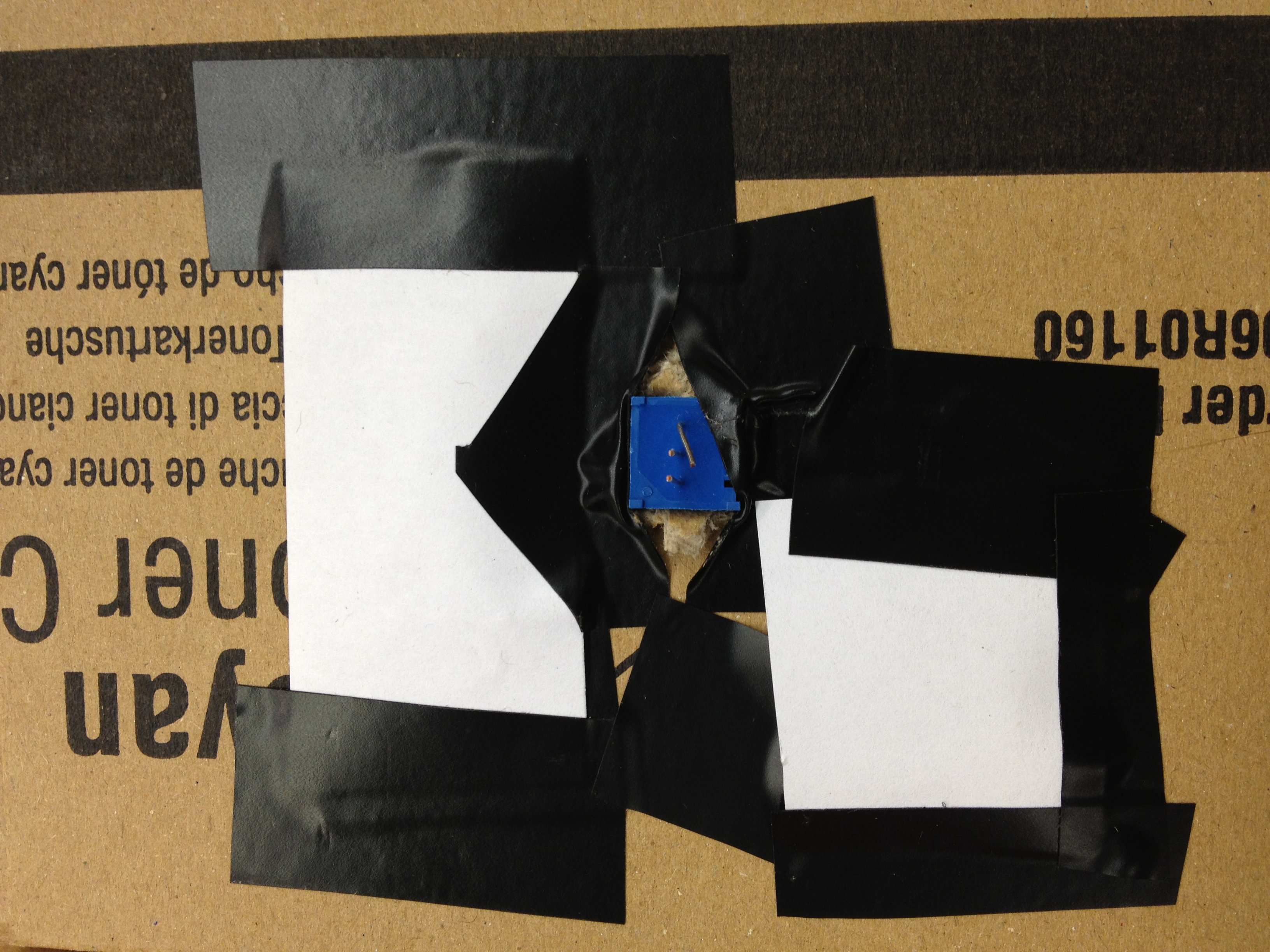
Physicians or volunteers can use our simple device to as a preliminary test for many neurological conditions. While the diagnosis is no means certain, it can be a useful tool to identify patients who are good candidates for further diagnostic testing. Below is an image of the system.


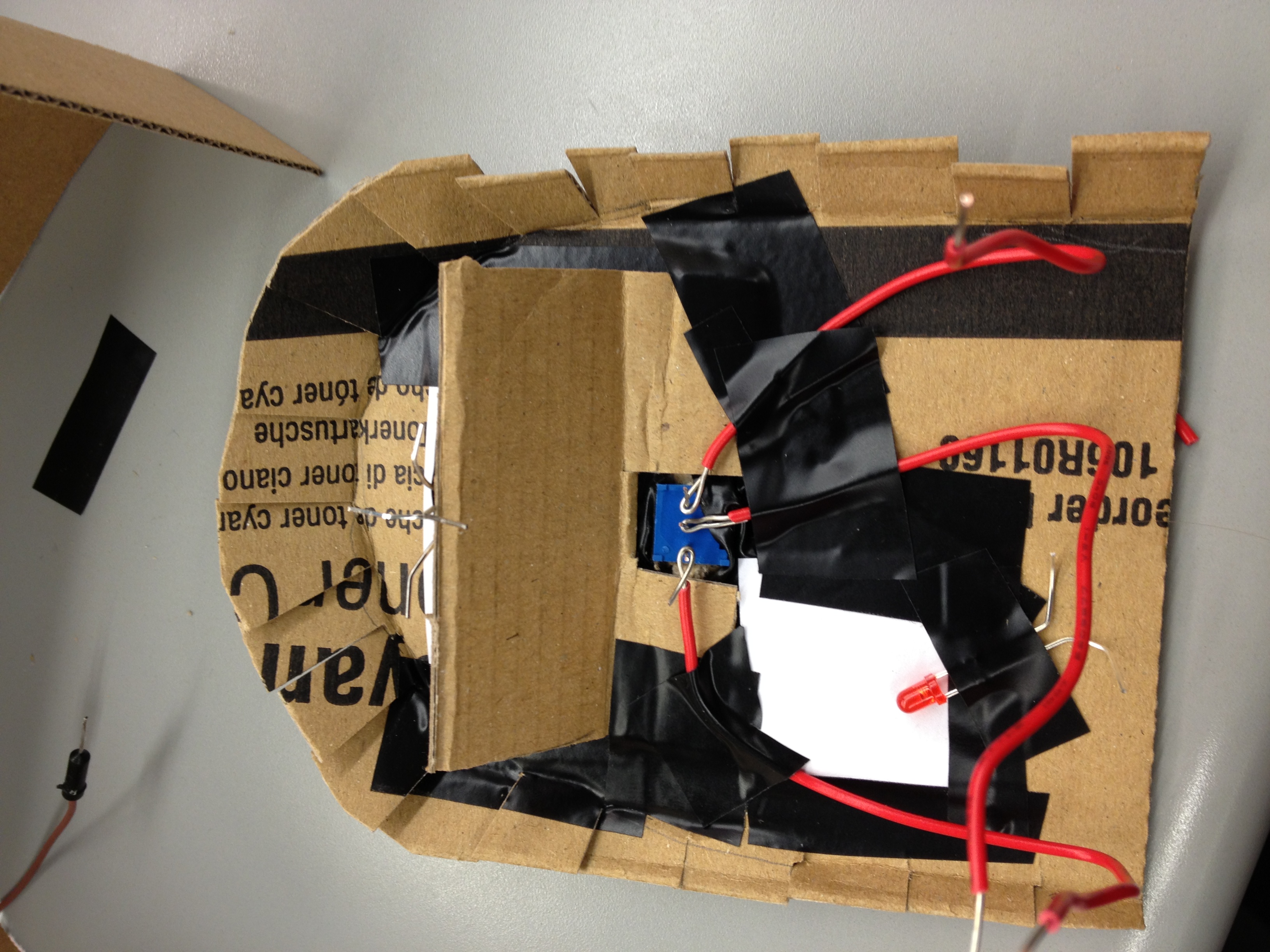
A look at the final product


Works Cited

Bozkurt, Biykem, and Douglas Mann. “Shortness of Breath.” Shortness of Breath. N.p., n.d. Web. 23 Feb. 2013.

“Movement Disorders.” American Association of Neurological Surgeons, n.d. Web. 23 Feb. 2013.

“Physical Examination: Diagnosis of Brain, Spinal Cord, and Nerve Disorders.” Physical Examination: Diagnosis of Brain, Spinal Cord, and Nerve Disorders: Merck Manual Home Edition. Merck, n.d. Web. 23 Feb. 2013.
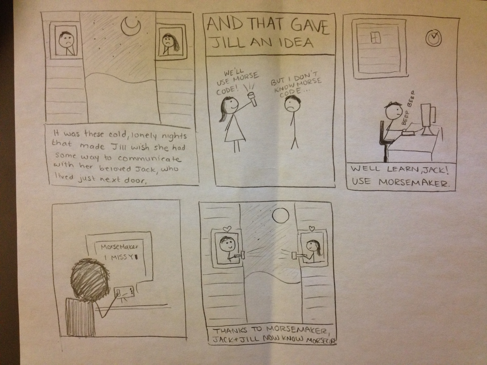
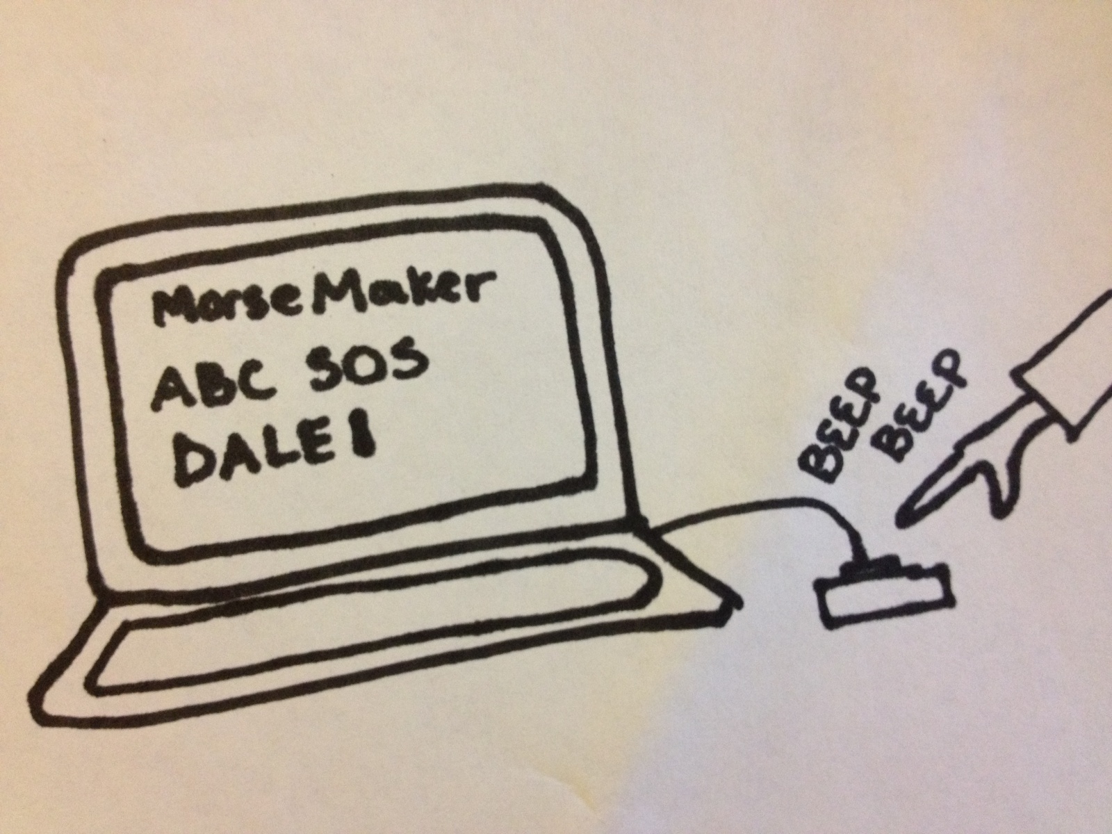
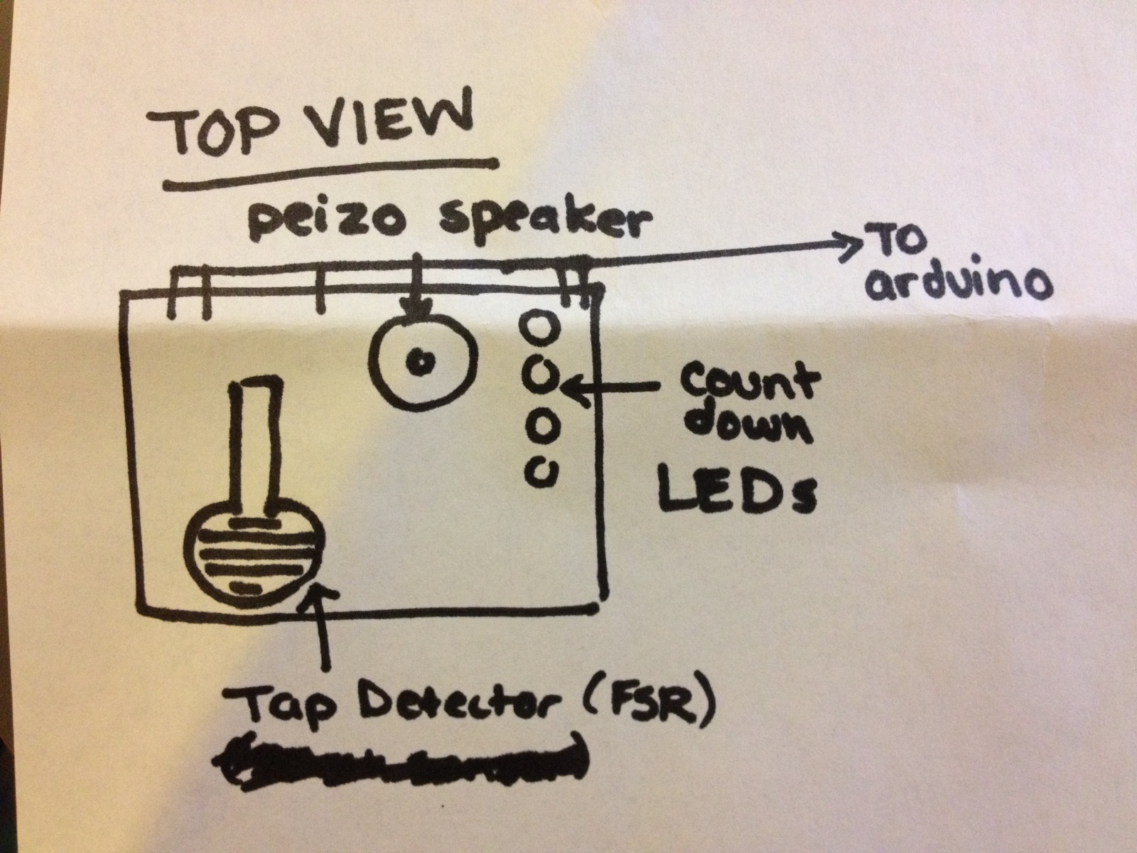
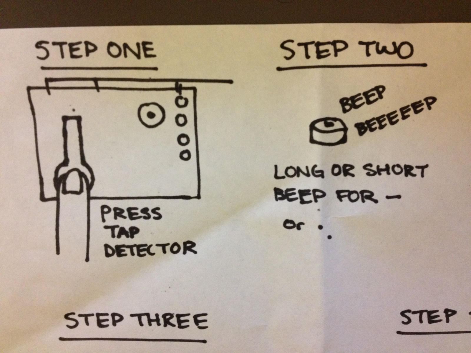
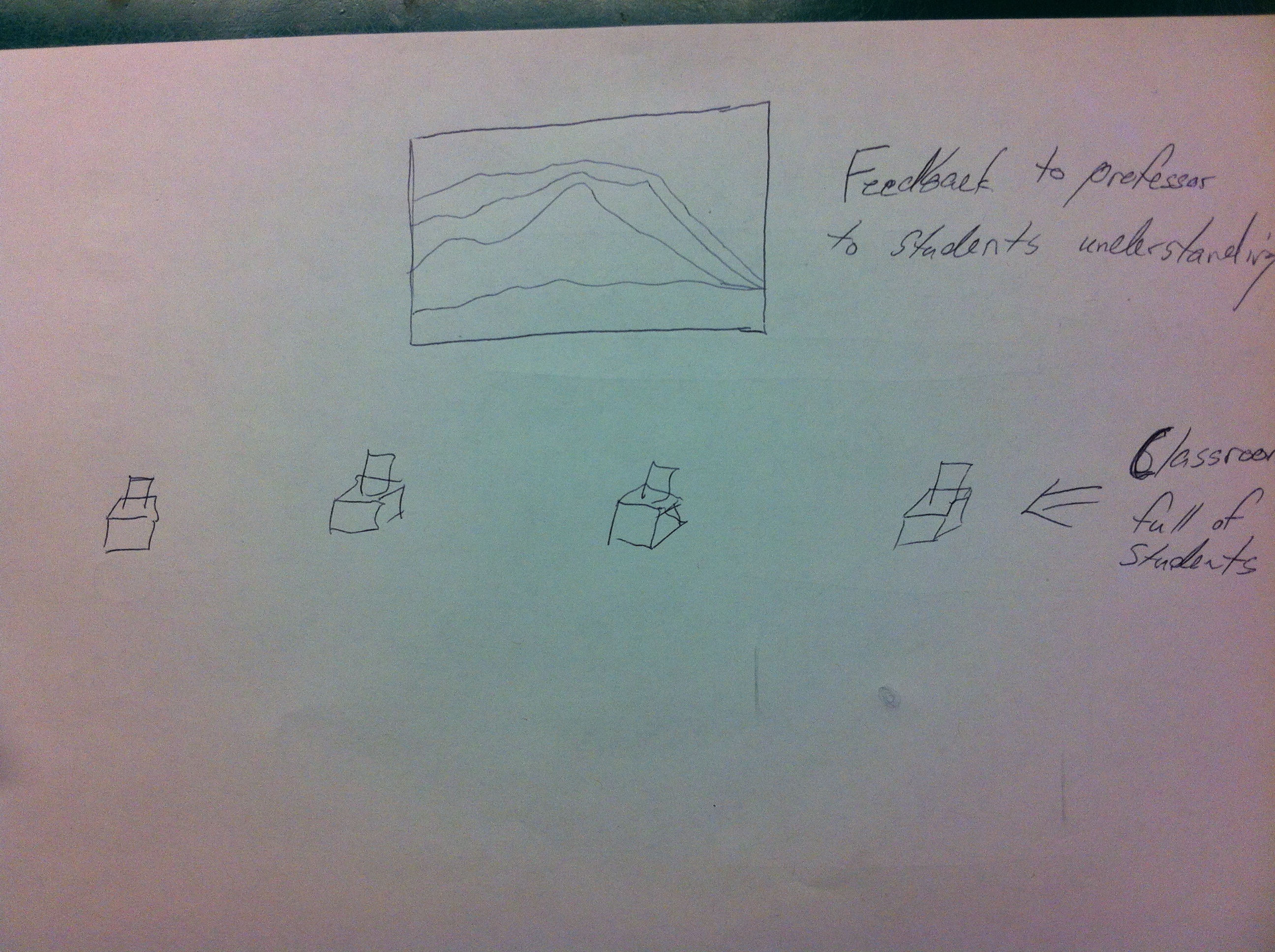
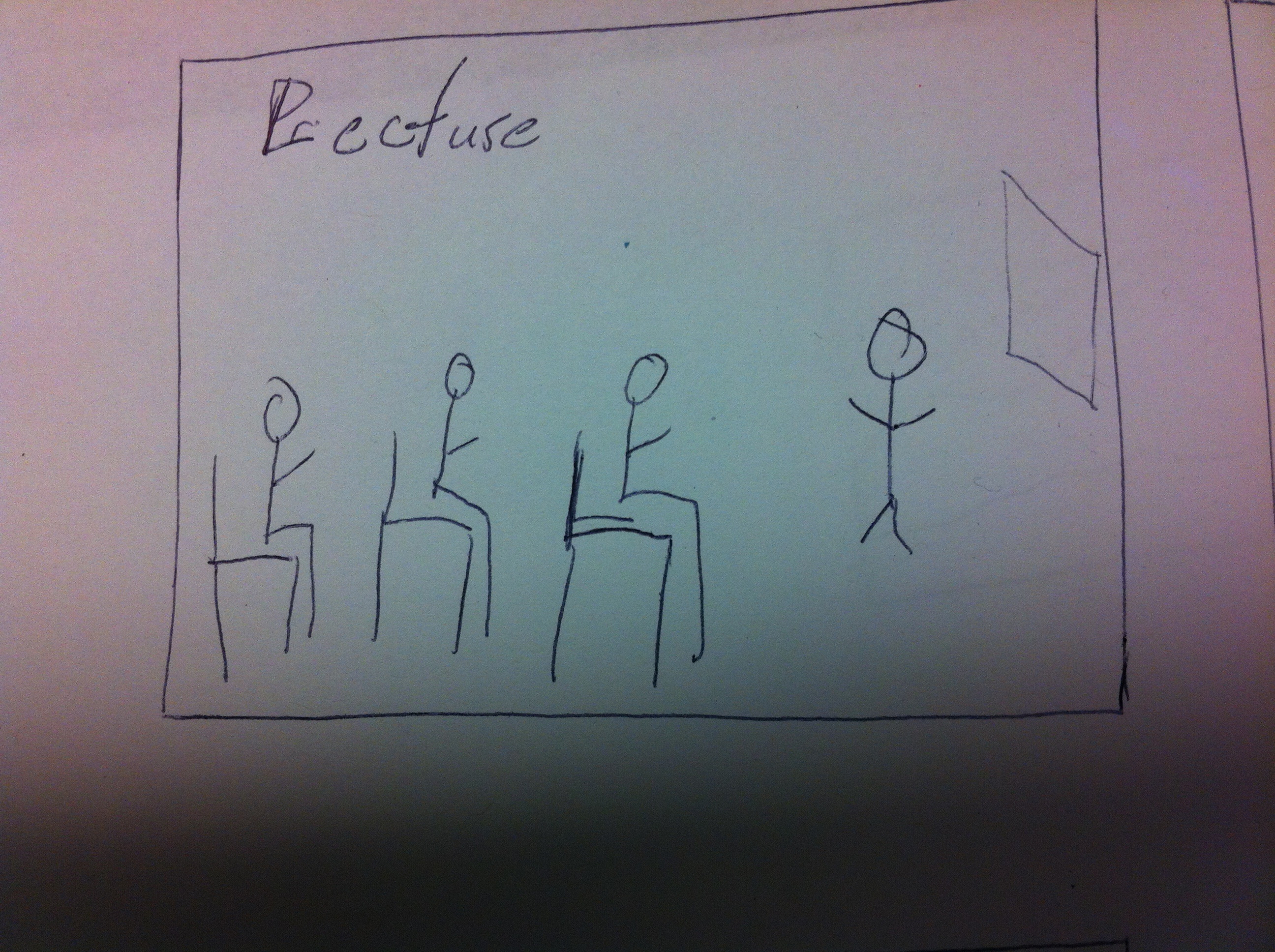
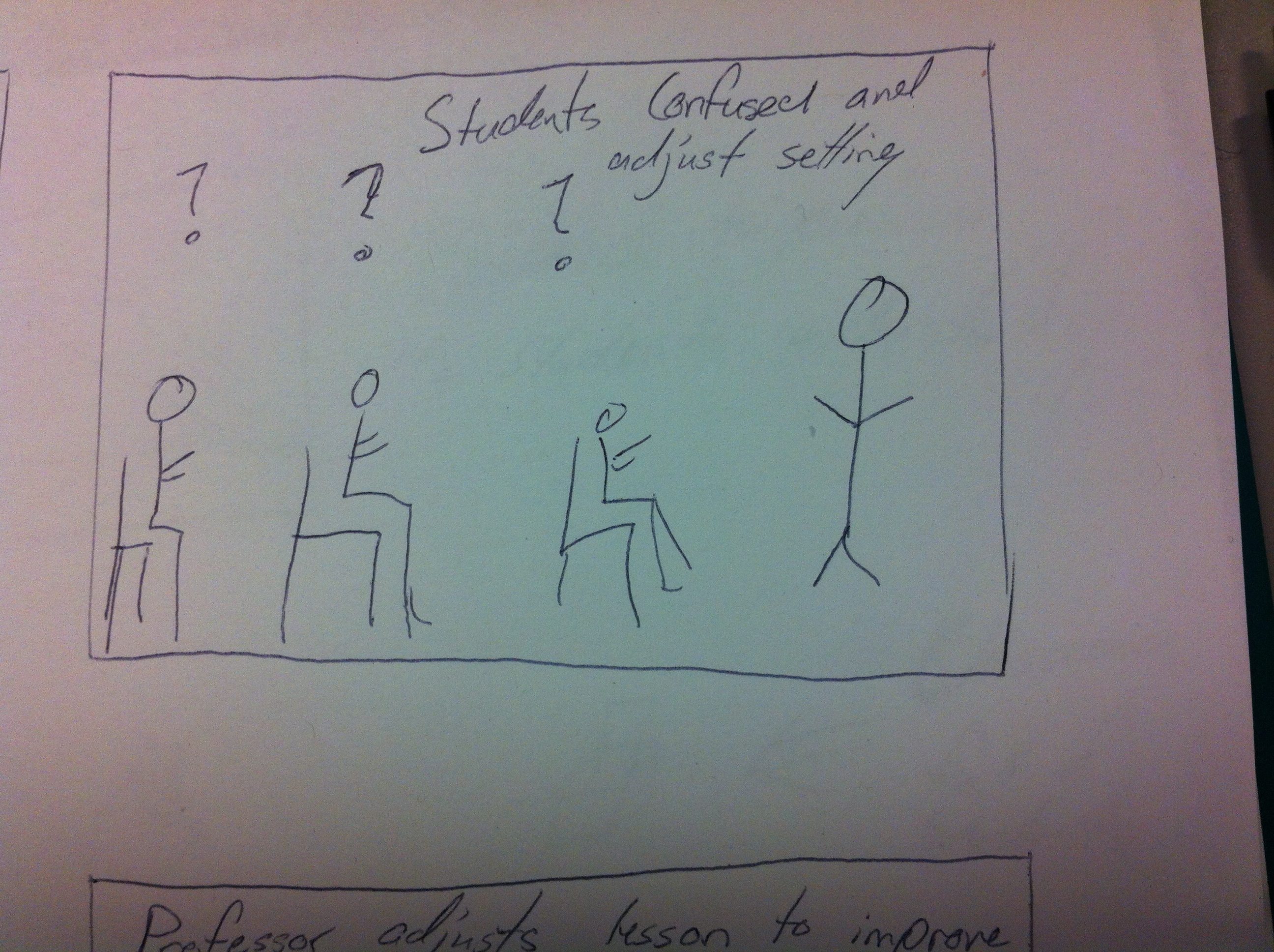
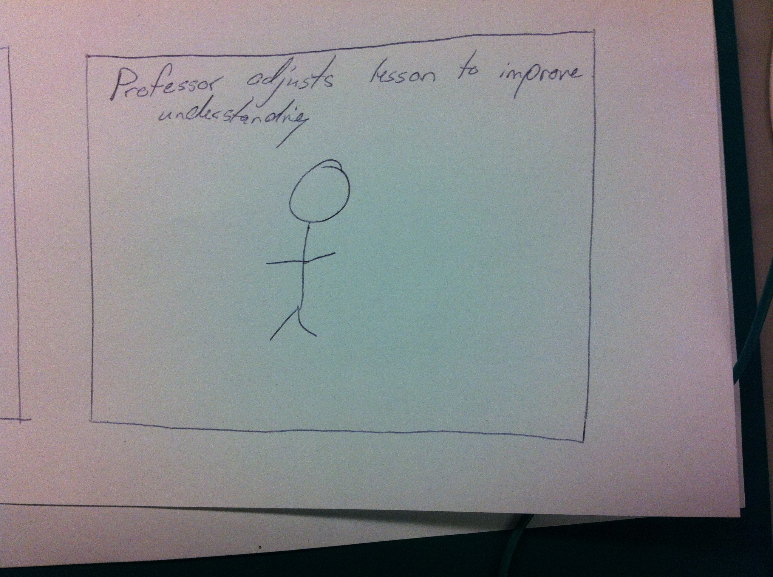
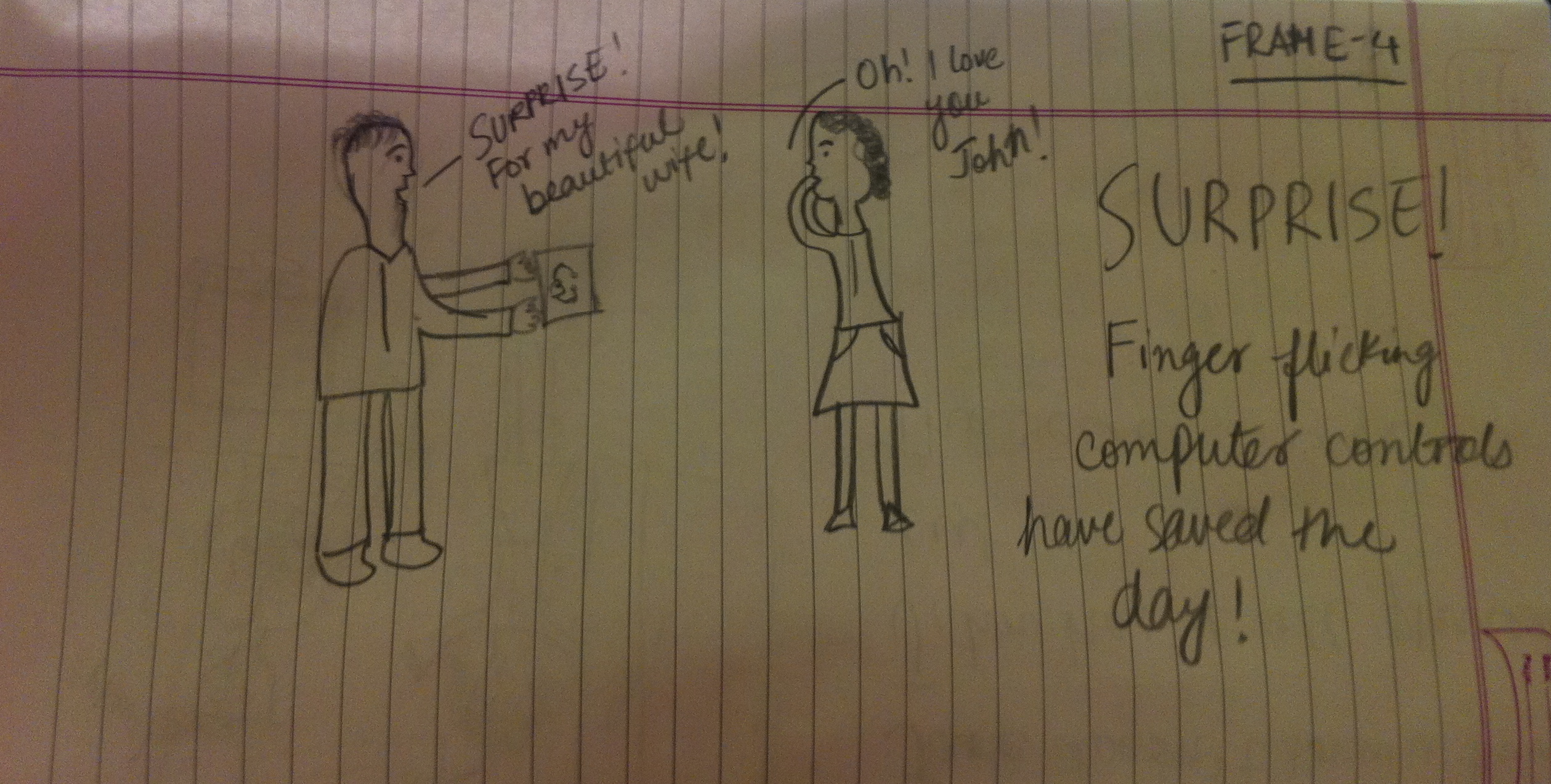
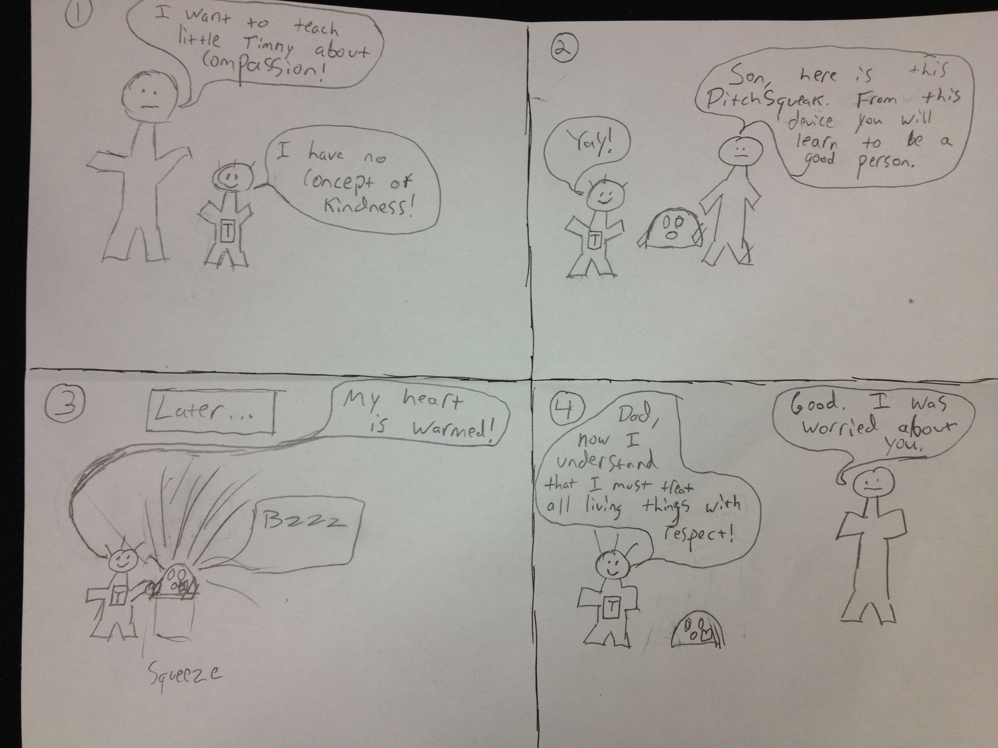
Story Board:


High Level Design Process:

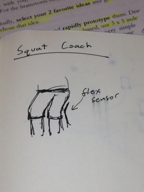
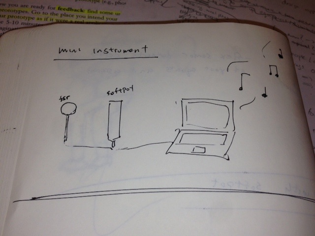
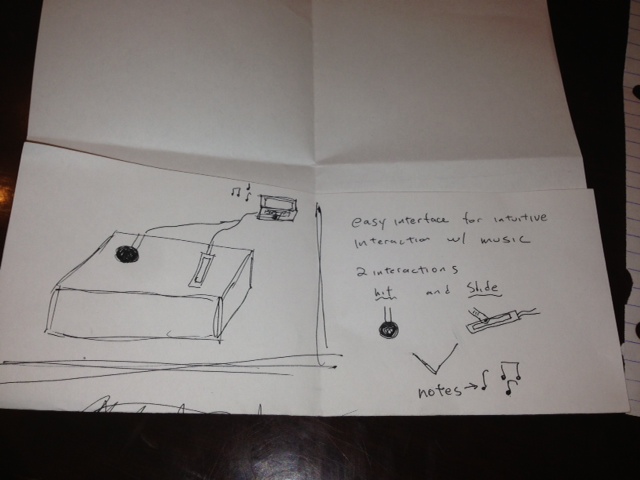
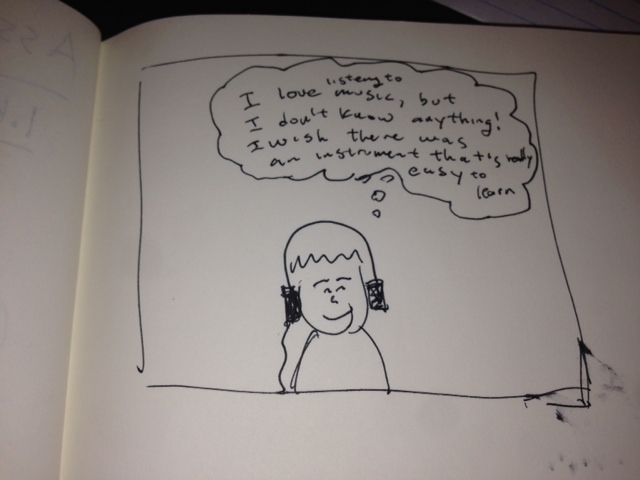
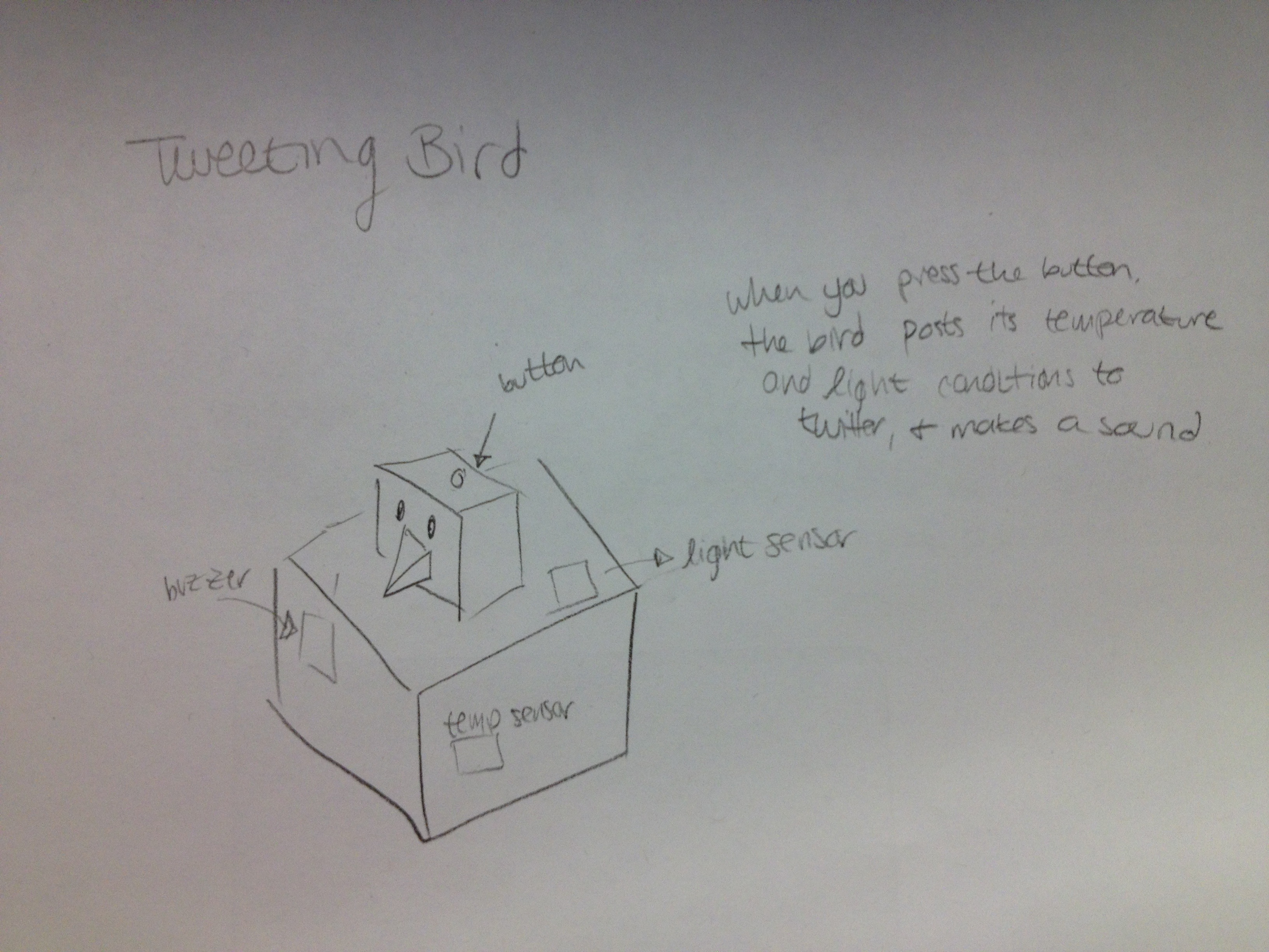
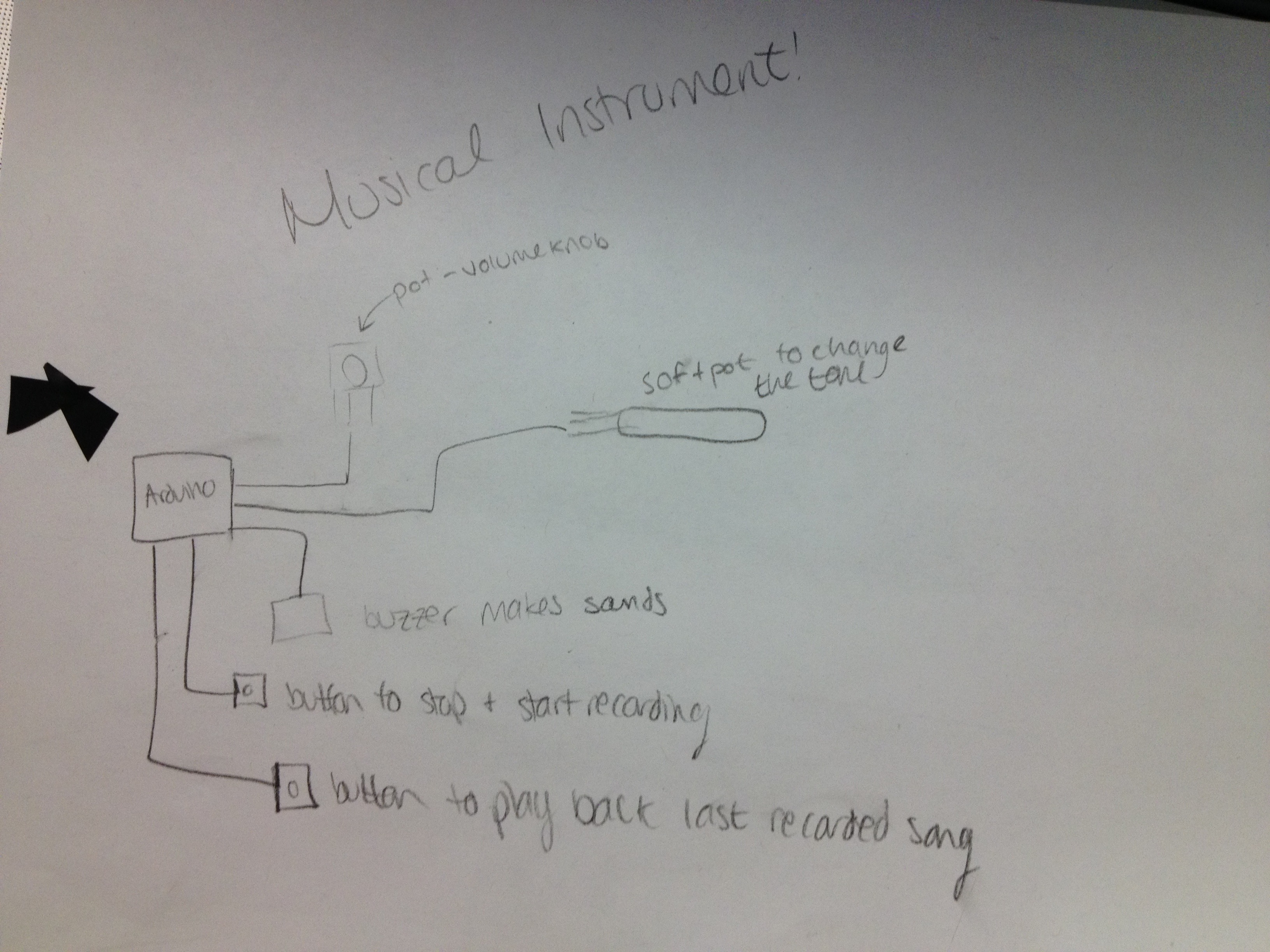
During the brainstorming stage we came up with a few ideas including:

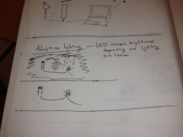
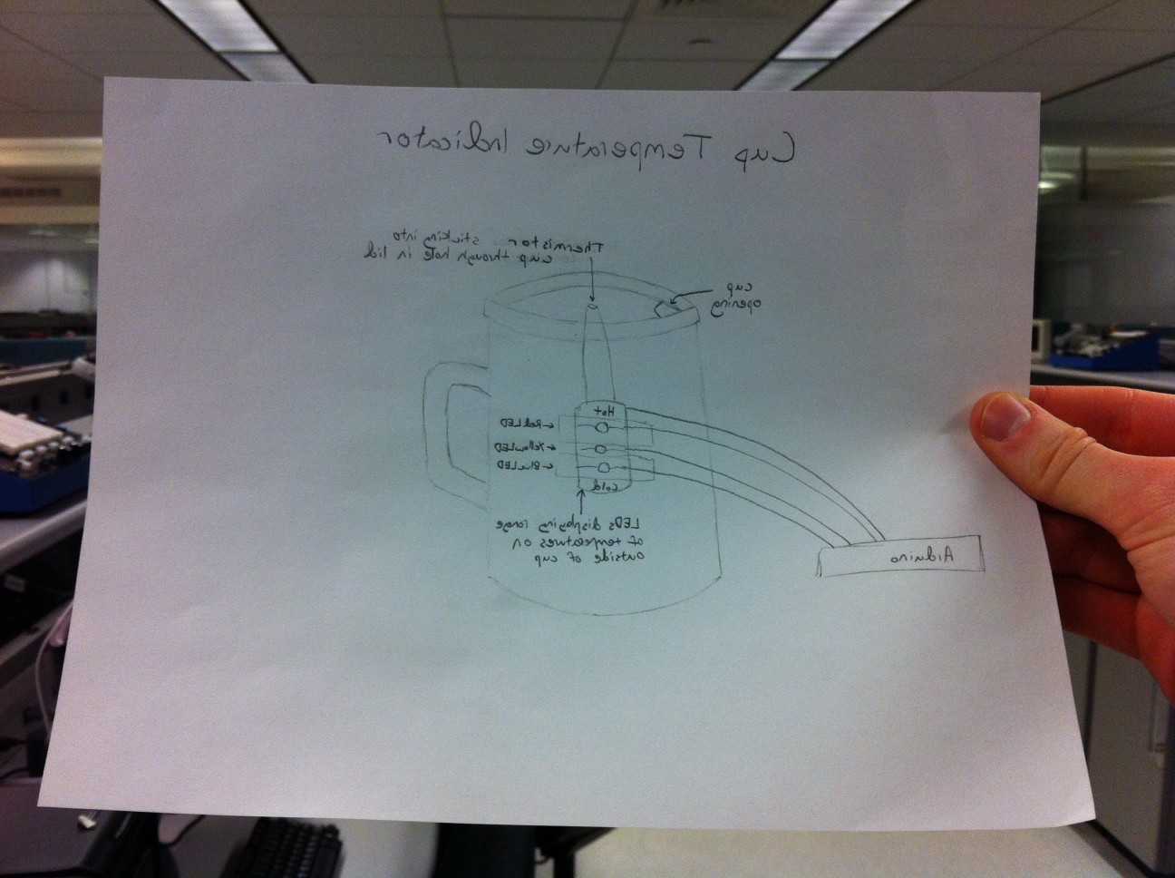
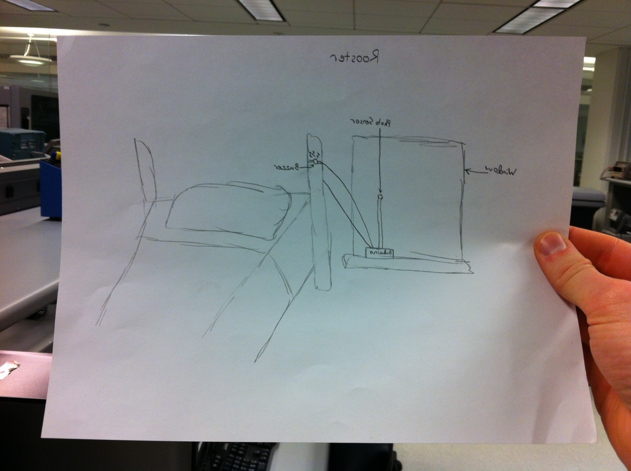
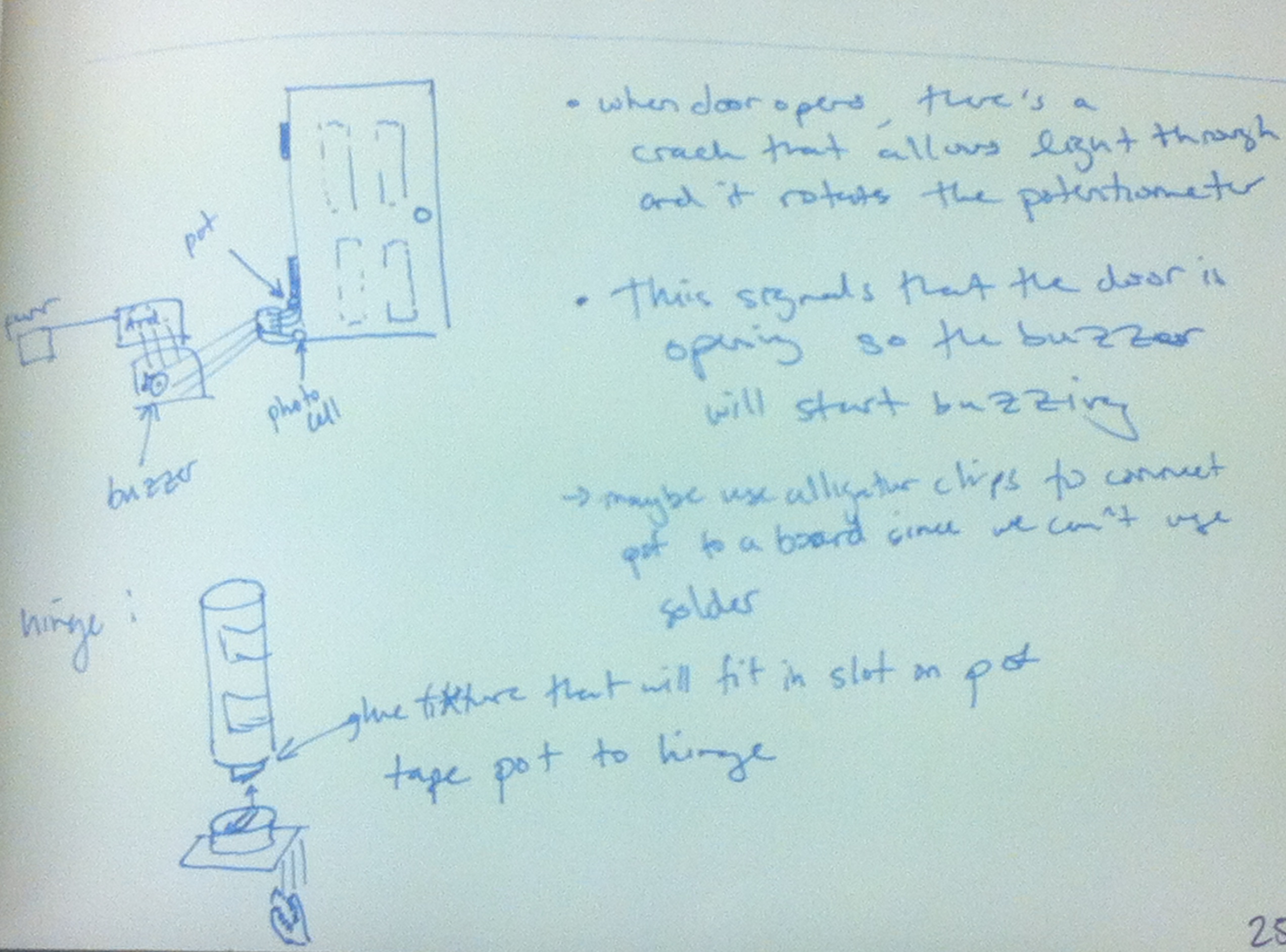
-A system to control a lamp based on lighting in the room (turn the lamp off if the room is light, turn the lamp on if the room is dark)

-A system to detect different types of coins using an FSR.

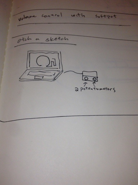
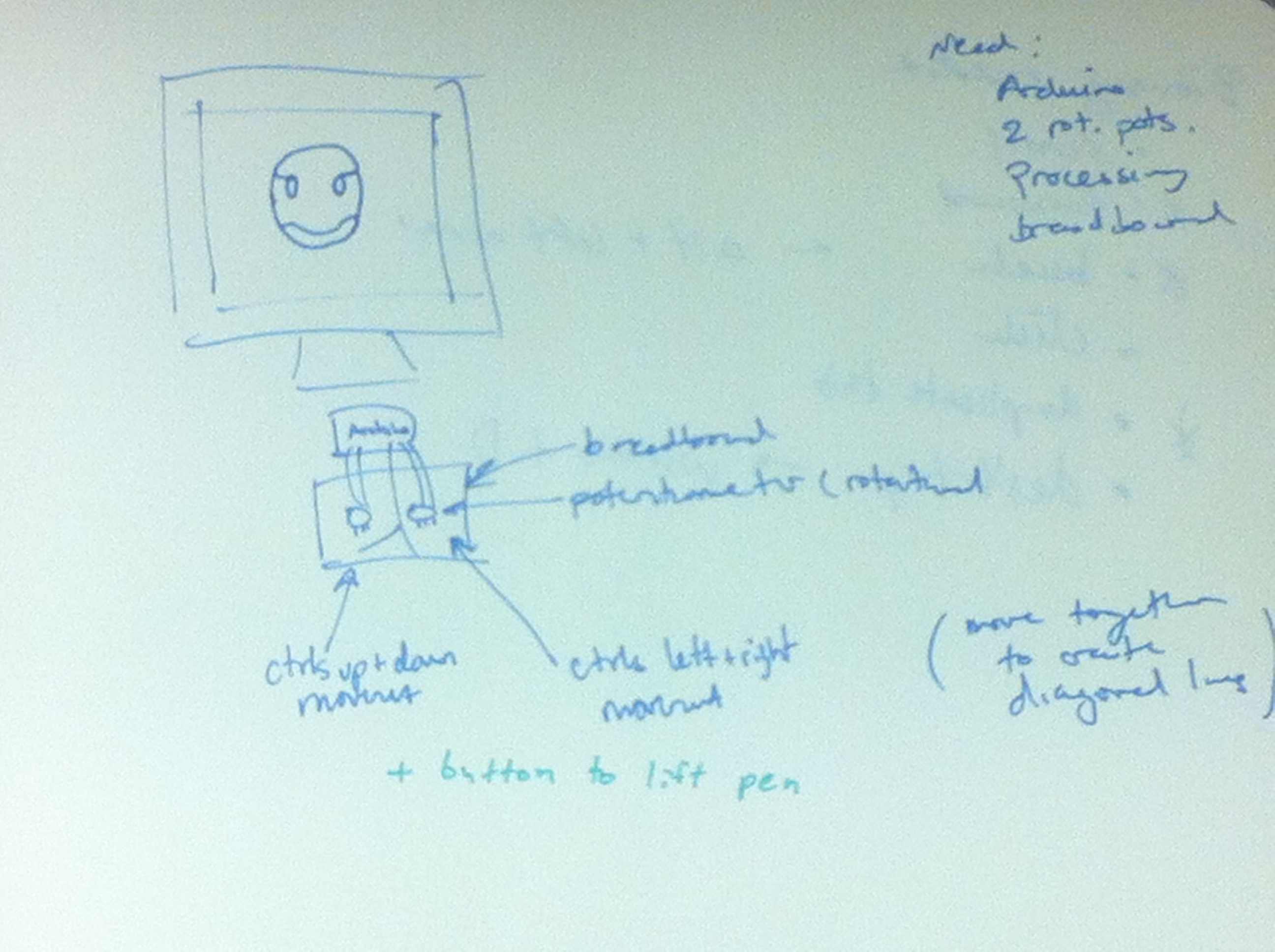
-A flex sensor controlled etch a sketch that draws to a computer monitor.

We decided to go with the medical testing suite because it’s flexible, potentially useful, and uses a wide array of the resistive sensors in our arsenal.

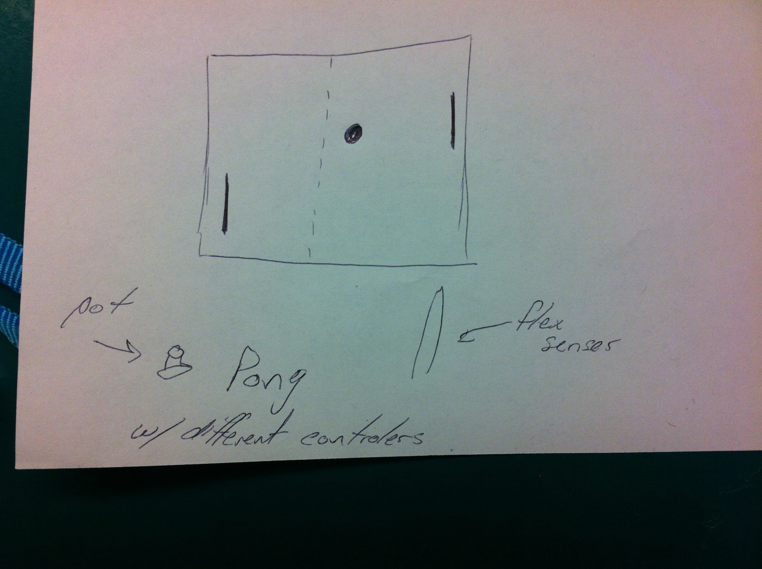
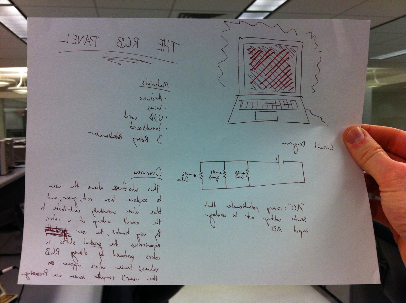
Our initial design looked something like this:

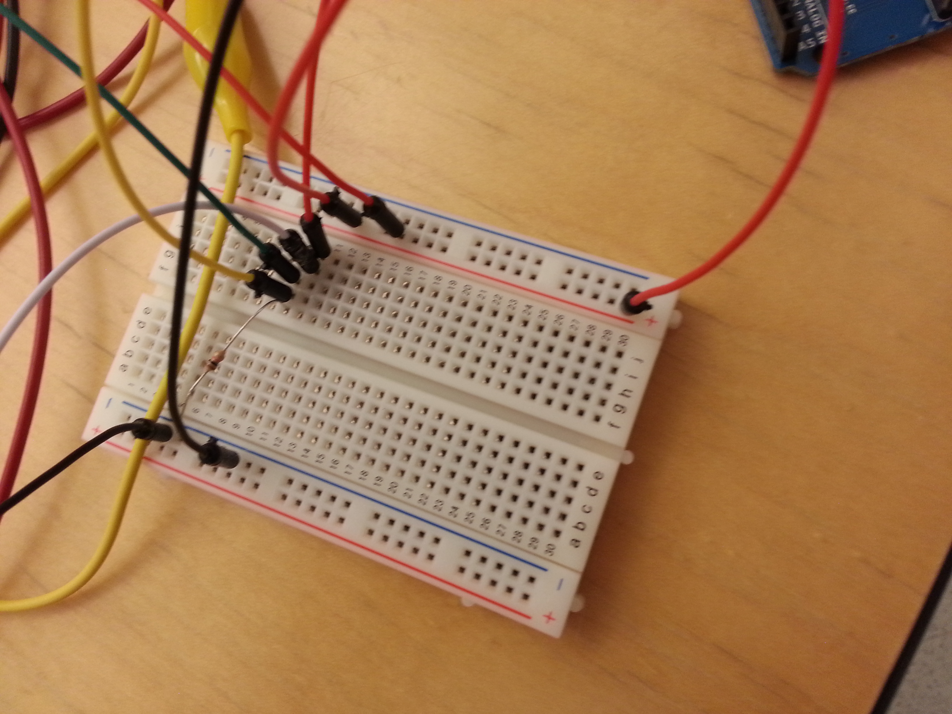
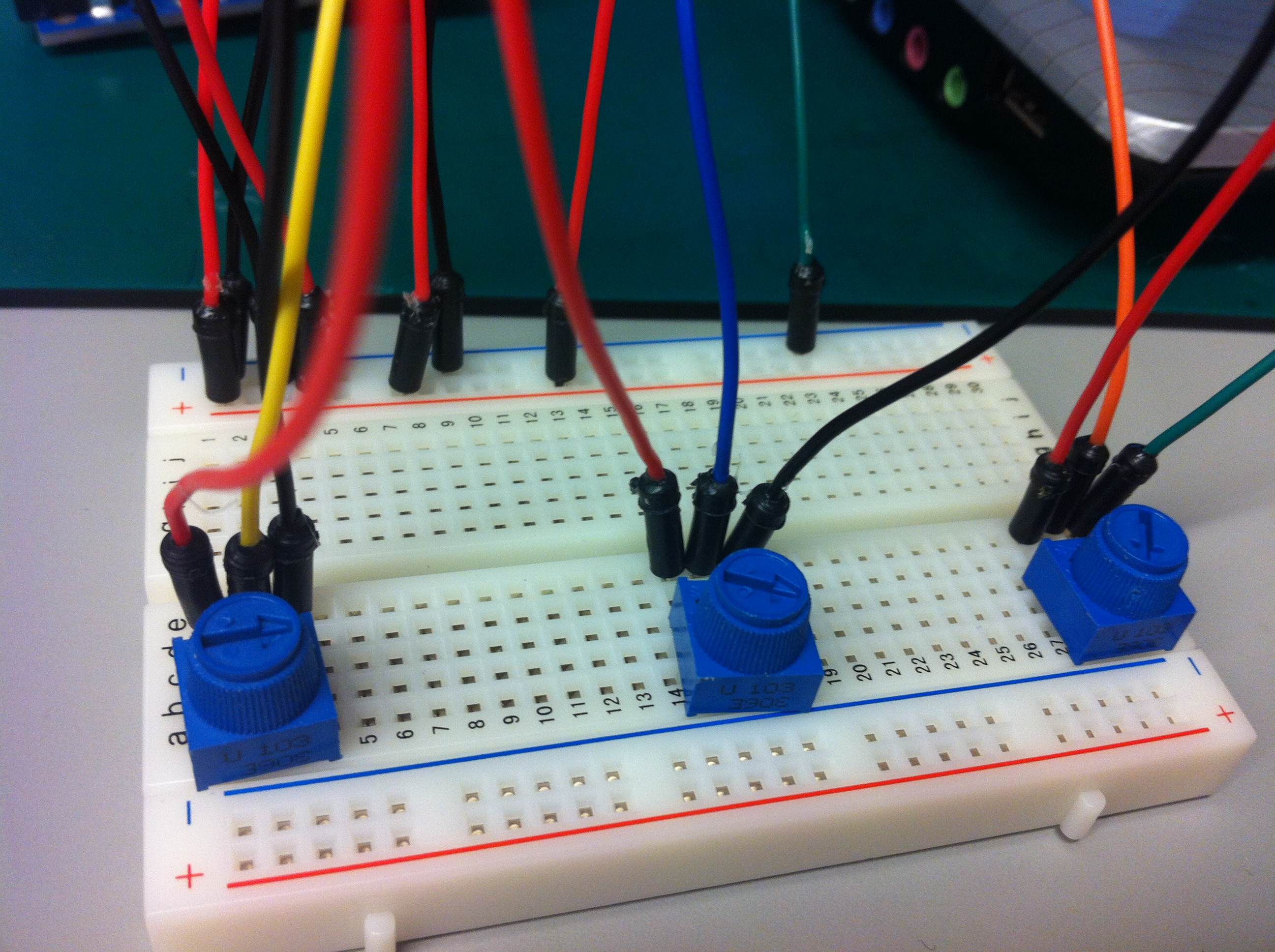
The idea was to have the 3 tests stationed radially on a platform. We would then have the user select a test using the pot in the center of the 3 tests. After writing our code though and implementing the tests on breadboards, we soon encountered difficulty with this setup. The challenge was that without soldering, we could not connect wires to our circuit components. To overcome these design issues, we changed our design to something more similar to the sketches below using several breadboards. In this setup, we moved the pot off to the side, and gave each test its own independent “station.”


The tests are spread out as far as possible using 3 breadboards. The pot is used to select the test.

Another design sketch when were realized we needed to rearrange circuit components.

The reaction time test “station”

Though this implementation was not as smooth or intuitive as the one we imagined, we were satisfied with the implementation given the materials we were working with. It took a bit of tweaking and trying different layouts to get our system in order, but in the end the system was structurally stable, functional, and reasonably easy to understand.

In addition to the physical layout of the testting system, we also had to work out the design of the tests themselves. We had the most trouble getting the spirometer working. Sometimes, the spirometer would not register when a user started blowing, while other times, it would think the user had stopped blowing when the user had not. To overcome these problems we tried directing the user’s breath through tubes, changing the position and width of the spirometer fan, and playing with the delay right before the start of the test. In the end it took the right modification of each of these factors to get the test working. Aside from the spirometer, we also had some difficulties detecting when the user is not touching the softpot. These difficulties were mitigated to some degree by adding a 10K resistor between the ground and output.

Overall, we were pleased with the way they way the design process went. By testing a series of different layouts, we think that we’ve arrived at an interface that provides a straightforward method of interacting with the system. We think the project could use a little more polish in order to make it more intuitive for first time users, but that much of this polish would come with being able to solder and permanently install the components into some housing.

Technical Design Description:

Reaction Time Test:

In the reaction time test, the user places their finger in the center of a softpot. Then, one of two LEDs placed the right and left of the softpot turn on. The user must move their finger in the corresponding direction as quickly as possible. If the user is quick enough and passes the test, the green feedback light flashes. It the user is too slow and fails the test, the red feedback light flashes.

Basic information on softpots can be found here: http://bildr.org/2012/11/touch-sliders-with-a-softpot-arduino/

Spirometer:

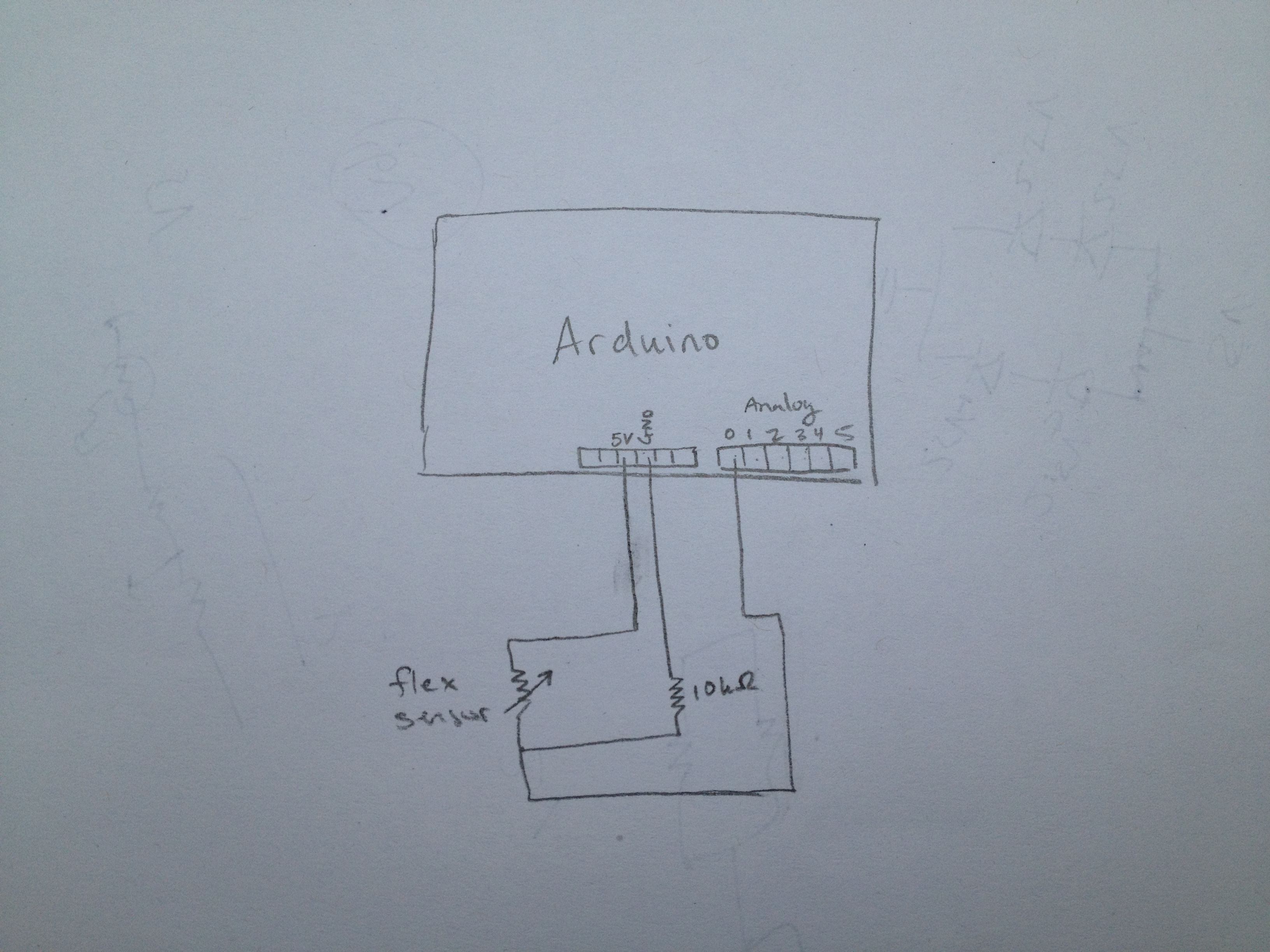
In the spirometer test, the user blows on the flex sensor for as long as possible. Our device times how long the user can keep the flex sensor bent beyond some minimum threshold. If the user blows long enough, hard enough, and passes the test, the green feedback light flashes. It the user fails the test, the red feedback light flashes.

Basic information on flex sensors can be found here: http://bildr.org/2012/11/flex-sensor-arduino/ 

Strength Test:

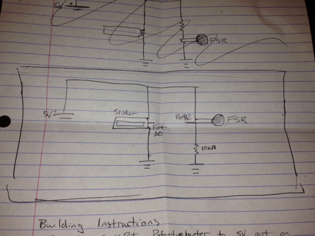
In the strength test, the user squeezes the FSR as hard as possible and our device measures the the maximum reading. If the user squeezes hard enough and passes the test, the green feedback light flashes. It the user fails the test, the red feedback light flashes.

Basic information on FSR’s can be found here: http://bildr.org/2012/11/force-sensitive-resistor-arduino/

Test Selection:

The device detects which test the user selects by reading the value from the pot. The range of pot values is divided into 3 sections, each of which correspond to a test.

Basic information on a pot can be found here: http://www.arduino.cc/en/Tutorial/Potentiometer
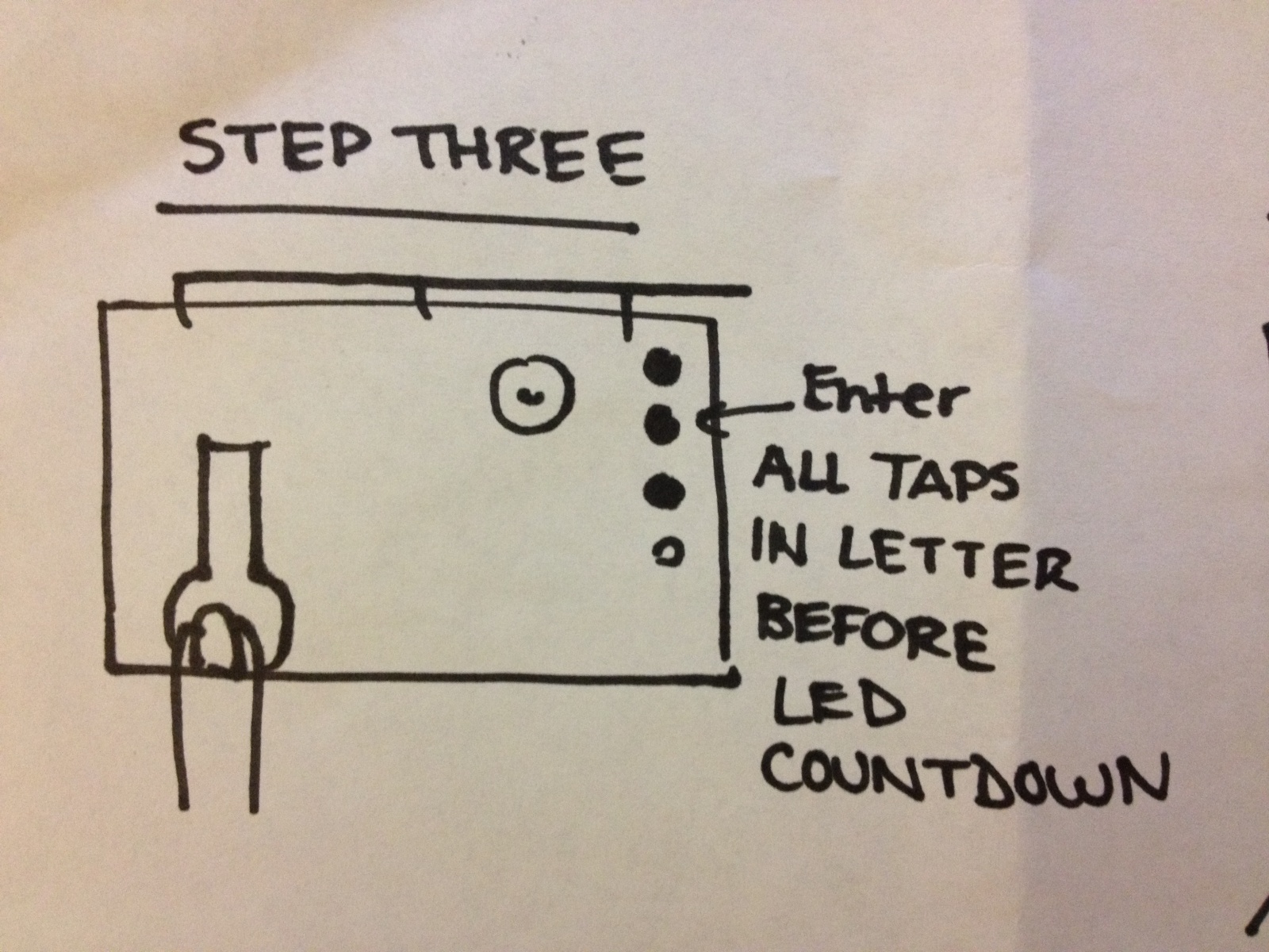
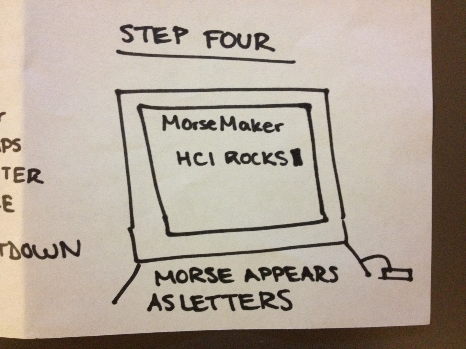
How to:

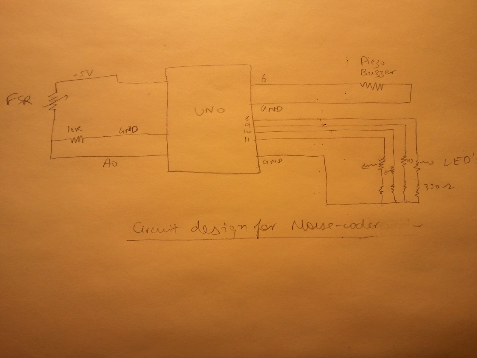
1) Install the FSR, pot, softpot, and flex sensor on a breadboard using the tutorials linked to above. Test each sensor by printing its value to Serial output.

2) Install 4 LEDs to be used in the tests. Write test code to make sure each one is wired correctly. (Refer to the Blink tutorial if help needed).

3) Upload the code below, making sure the input pins of your sensors and LEDs correspond to the pins in the code.

4) Test the system. If everything is set up correctly, the system should work as it does in the video. If it does not work, check your wire connections. If all of your wires seem to be connected correctly, write Serial.print() statements in the code to help debug your system.

5) Make your interface more usable by constructing housing out of cardboard or other material, and adding any other features such as a fan for the spirometer.

The Code:

typedef enum {
  LUNG_MODE,
  REACTION_MODE,
  SQUEEZE_MODE,
} 
game_mode_e;

game_mode_e gameMode;
int time_msec;

int redLedPin = 2;
int greenLedPin = 3;
int slideRightLedPin = 4;
int slideLeftLedPin = 5;

int flexPin = 0;
int flexReading;

int maxDelay = 30;
int delay_ms;

int maxFlexThresh = 315;
int flexTarget = 315;

int middleOfRT = 600;
int minRT= 100;
int slideLeftThreshold = 100;
int slideRightThreshold = 900;
int targetRT = 150;

int slidePin = 1;
int slideReading;

int potPin = 2;
int potMax = 1023;
int numChoices = 3;

int randChoice;

int squeezeReading;
int squeezePin = 3;
int maxSqueezeThresh = 400;
int squeezeTarget = 400;

// flash a given led
void flashLed (int ledNum) {
  analogWrite(ledNum, 0);
  delay(50);
  analogWrite(ledNum, 255);
  delay(200);
  analogWrite(ledNum, 0);
  delay(50);
}

void readPot() { 
  int potReading = analogRead(potPin);

  if (potReading < 340) {
   gameMode = LUNG_MODE;
  }
  else if (potReading < 681) {     gameMode = REACTION_MODE;   }   else {     gameMode = SQUEEZE_MODE;   }   Serial.print("Game Mode: ");   Serial.println(gameMode); } void setup(void) {   // We'll send debugging information via the Serial monitor   Serial.begin(9600);   gameMode = REACTION_MODE;   flashLed(redLedPin);   flashLed(greenLedPin);   randomSeed(analogRead(0)); } void loop(void) {   readPot();   switch (gameMode) {   case LUNG_MODE:     flexReading = analogRead(flexPin);       Serial.print("Flex reading = ");     Serial.println(flexReading);     // detect blowing start     while (flexReading > maxFlexThresh){
      Serial.println(flexReading);
      delay(50);
      flexReading = analogRead(flexPin);  
    }
    time_msec = 0;
    while (flexReading < flexTarget){
      delay(100);
      time_msec += 100;
      flexReading = analogRead(flexPin);  
    }
    if (time_msec < 1000){
      flashLed(redLedPin);
    } 
    else {
      flashLed(greenLedPin);
    }
    break;
  case REACTION_MODE:
    flashLed(slideLeftLedPin);
    flashLed(slideRightLedPin);
    slideReading = analogRead(slidePin);  

    // wait for them to put their finger in the middle
    while (slideReading < minRT){       slideReading = analogRead(slidePin);         flashLed(redLedPin);     }     // ready to go     flashLed(greenLedPin);     flashLed(greenLedPin);     delay(500);     // calculate random delay     delay_ms = random(maxDelay) * 100;     time_msec = 0;     delay(delay_ms);       randChoice = random(2);              // based on previously calculated randomness       if (randChoice == 0){         flashLed(slideLeftLedPin);       // while their finger isn't all the way on the left       while (slideReading > slideLeftThreshold){
        delay(10);
        time_msec += 10;
        slideReading = analogRead(slidePin);  
      }
    } 
    else{
      flashLed(slideRightLedPin);

      // while their finger isn't all the way on the right
      while (slideReading < slideRightThreshold){
        delay(10);
        time_msec += 10;
        slideReading = analogRead(slidePin);  
      }
    }

    // if they beat the target time
    if (time_msec < targetRT){
      flashLed(greenLedPin);
      flashLed(greenLedPin);
    }
    else{
      flashLed(redLedPin);
      flashLed(redLedPin);
    }

    break;
  case SQUEEZE_MODE:
    squeezeReading = analogRead(squeezePin);  
    // detect blowing start
    while (squeezeReading < maxSqueezeThresh){       delay(50);       squeezeReading = analogRead(squeezePin);       }          time_msec = 0;     while (squeezeReading > squeezeTarget){
      delay(100);
      time_msec += 100;
      squeezeReading = analogRead(squeezePin);  

    }
    if (time_msec < 3000){
      flashLed(redLedPin);
    } 
    else {
      flashLed(greenLedPin);
    }
    break;

  default:
    Serial.println("Unsupported mode");
  }
  delay(250);
}

L1

Names:
Farhan Abrol
Dale Markowitz
Collin Stedman
Raymond Zhong

Group Number: 4

Description

The interface consists of a force sensitive resistor, which the user either taps or holds to send dots or dashes, respectively. A piezo sensor beeps to provide feedback; a short pulse tells the user they have hit the FSR with enough force to trigger it, and a long pulse tells them they have held it down long enough to enter a dash.

Morse code is tricky to interpret, because not all characters are the same length (i.e. one letter might be a single dot, while another is several dots). In order to get around this, we set up a time interval for which dots or dashes a user enters are considered a single character. This is denoted by four LEDs that “count down” to indicate how long the user has to enter the next dot or dash within the same character.

Assessment

When deciding on what to build for this assignment, our team thought of many options involving interacting with sound through touch. We wanted to build something that was both simple and fun to play with. We went through many ideas involving sound synthesis (especially a drum simulator). Ultimately, we decided on a Morse code interpreter, because we felt it fit well with the supplies we had at hand.

All in all, we were very happy with the way our morse code converter turned out. Although the description sounds complicated, the device is intuitive once you sit down in front of it — and we had fun typing letters on a screen. Perhaps the thing that we are unhappiest with about our device is that it is not super relevant today (what a shame! it’s so fun to play with). It’s a device that might only be appreciated by specialists or true nerds. Whatever those are. 🙂

Storyboard

Photo Feb 27, 12 50 29 PM

Sketches

Photo Feb 27, 12 49 07 PM Photo Feb 27, 12 49 12 PM  Photo Feb 27, 12 50 52 PM Photo Feb 27, 12 50 59 PM Photo Feb 27, 12 51 04 PM

Parts List

Breadboard, wire, wire cutter/stripper
Arduino Uno
Force Sensitive Resistor
3 Red LEDS, 1 Yellow LED, and appropriate resistors for 5V source (varies by LED)
Piezo speaker
Computer and source code

Make it yourself!

Only requires everyday prototyping parts!

1. Obtain a force-sensing resistor, an Arduino microcontroller, an electronic breadboard, as well as several LEDs and appropriate resistors for each component.
2. Attach the force-sensing resistor to the center of the breadboard, in such a way that it can be taped onto the edge of the top of the breadboard.
3. Connect the FSR to the analog sensing port of the Arduino, using a pull-down resistor connected to ground.

circuit1

3. On the opposite side of the breadboard, attach a row of LEDs, connecting them to digital output pins on the Arduino through 330 ohm resistors.
4. Tape the FSR onto the breadboard so that it can be easily tapped or held with a finger.
5. Set the FSR pin, the first LED pin, and the number of LEDs used in the Arduino program.
6. Download the Arduino program, and run the keyboard filter on your computer.

Congrats, you can now type in Morse code!

Arduino Code

/* FSR simple testing sketch. 

Connect one end of FSR to power, the other end to Analog 0.
Then connect one end of a 10K resistor from Analog 0 to ground 
*/

int fsrPin = 0;     // the FSR and 10K pulldown are connected to a0
int fsrThreshold = 20;
int fsrReading;     // the analog reading from the FSR resistor divider
int delayTime = 10;
int buzzerPin = 6;

// number of delay loops for each symbol
int dotLength = 1;
int dashLength = 20; // 200ms
int letterSepLength = 100; // 1000ms
int pauseLength;
int tapLength;

// length of tones emitted for each button press
int dotToneLength = 30;
int dashToneLength = 100;

// LED status display
int firstLEDpin = 8;
int numLEDpins = 5;

void setup(void) {
  Serial.begin(9600);   
}

void sendLetterEnd() {
  Serial.println("2");
}

void sendDot() {
  Serial.println("0");
  tone(buzzerPin, 440);
  delay(dotToneLength);
  noTone(buzzerPin);   
}

void sendDash() {
  Serial.println("1");
  tone(buzzerPin, 1000);
  delay(dashToneLength);
  noTone(buzzerPin);
}

void lightLEDs() {
  for (int i = 0; i < numLEDpins; i++) {
    digitalWrite(firstLEDpin + i, 1);
  }
}

void dimLEDs() {
  for (int i = 0; i < numLEDpins; i++) {     if (pauseLength > i*letterSepLength/numLEDpins) {
      digitalWrite(firstLEDpin + i, 0);
    }
  }
}

void beep() {
}

void loop(void) {
  fsrReading = analogRead(fsrPin);  

  if (fsrReading < fsrThreshold) {     if (dashLength > tapLength && tapLength > dotLength) {
      sendDot();
      lightLEDs();
    }
    if (pauseLength == letterSepLength) {
      sendLetterEnd();
    }
    dimLEDs();
    tapLength = 0;
    pauseLength++;    
  } else {
    if (tapLength == dashLength) {
      sendDash();
      lightLEDs();
    }
    pauseLength = 0;
    tapLength++;
  }
  //Serial.print("Analog reading = ");
  //Serial.println(fsrReading);     // the raw analog reading
    delay(delayTime);
}

Processing Code:

github.com/dalequark/morsecode

[kaltura-widget uiconfid=”1727958″ entryid=”0_0e1153da” width=”400″ height=”360″ addpermission=”” editpermission=”” /]

L1 – SoundBox

Group #1

  • Avneesh Sarwate (asarwate@)
  • John Subosits (subosits@)
  • Joe Turchiano (jturchia@)
  • Kuni Nagakura (nagakura@)
  • Yaared Al-Mehairi (kyal@)

Ideas and Sketches

  1. Squat Coach – Detects the depth of your squats and assesses your form.

    Flex sensor is positioned to run up the back of knee joint

    Flex sensor is positioned to run up the back of knee joint

  2. Etch-A-Sketch – Arduino version of Etch-A-Sketch game.

    Users control stylus with 2 rotational potentiometers

    Users control stylus with 2 rotational potentiometers

  3.  Adaptive Lighting – LED changes brightness depending on lighting of room.

    Photo cells connected to LED vary brightness of light emission based on surrounding light

    Photo cells connected to LED vary brightness of light emission based on surrounding light

  4. SoundBox – Musical instrument with a simple interface for intuitive interaction and immediate results.

    Users can control amplitude with FSR (force sensing resistor) and pitch with slider

    Users can control amplitude with FSR (force sensing resistor) and pitch with slider

We decided to choose idea #4. While we liked our other ideas, we felt creating a SoundBox would be the most feasible and rewarding endeavor.

Project Description

We built a musical instrument, called the “SoundBox”. The “SoundBox” allows users to create notes by applying pressure to a force sensing resistor. The amount of pressure applied determines the volume of the note and users can control the pitch of each note they create with a SoftPot Membrane Potentiometer (slider). When users create notes, a python program reads the incoming signals from the USB port (which the Arduino is speaking to). Our python program then feeds these signals to ChucK, an audio programming language, which then creates the sounds you hear. We are definitely pleased with the result of our project. The intuitive and simple nature of the “SoundBox” interface allows any user to create a variety of sounds and patterns. Thus, in giving the gift of music (albeit limited) to users, we feel that our project is successful. One thing we could certainly improve is the limited functionality of our “SoundBox”. For example, we could add a switch to the Arduino which would enable users to toggle through ChucK instruments (as of now the default instrument is the mandolin). Furthermore, we could add multiple sliders to enable users to play multiple notes at once. What’s more, we could speak to any MIDI receiving Audio Software, such as Ableton Live or Logic (which have extensive sound libraries), to fashion sounds out of user input. As such, there is definitely a lot of room for improvement in our design, which would seriously enhance the functionality of the “SoundBox”.

SoundBox

SoundBox

Storyboard

Loves music but can't play any instruments

I love music but I can’t play any instruments

This instrument is really easy to play!

This instrument is really easy to play!

'Making music'

‘Making music’

Wow, that was so easy!

Wow, that was so easy!

Photos and Video

SoundBox interface closeup

SoundBox interface closeup

SoundBox interface connections

SoundBox interface connections

Arduino setup

Arduino setup

Breadboard setup

Breadboard setup

Arduino and breadboard

Arduino and breadboard

Whole system

Whole system

Movie on 2013-02-26 at 21.36

Evaluation

The FSR was quite effective at picking up varying pressures and gave a
pretty convincing and natural feeling “pluck” that was sensitive to
tap intensity. The Softspot was adequate, but would sometimes behave a
bit unpredictably. We weren’t sure whether this was because of
hardware issues or simply our own clumsiness with a controller that
required very precise motions. Regardless, it was very intuitive to
use. Next time, we would have possibly added some kind of visualizer
to see what note you are at on the Softspot, or maybe added the
functionality to “bend” notes by sliding on the Softspot after
pressing the FSR to “pluck” a note.

List of Parts

  1. Arduino
  2. Breadboard
  3. Force Sensing Resistor
  4. Soft
  5. 10 kΩ Resistor
  6. Wires
  7. Alligator Wires
  8. Cardboard Box (to mount resistance)
  9. Electrical Tape

Circuit

"SoundBox" Circuit Diagram

“SoundBox” Circuit Diagram

Instructions

  1. Place sensors on cardboard box at comfortable distance and clip the alligator clips onto the ends. Use electrical tape to hold down the wires to the box. 
  2. Connect SoftPot Potentiometer to 5V port on one end and ground on the other. Input goes to Port A0 on the Arduino. (follow pictures and circuit diagram)
  3. Connect Force Sensing Resistor in series with 10kΩ resistor. Input to Port A2 on the Arduino. (follow pictures and circuit diagram)

Code

SimpleMidi.ino

#include <MIDI.h>

/* FSR simple testing sketch.

Connect one end of FSR to power, the other end to Analog 0.

Then connect one end of a 10K resistor from Analog 0 to ground

For more information see www.ladyada.net/learn/sensors/fsr.html */
int sliderPin = 0; // the FSR and 10K pulldown are connected to a0
int fsrPin = 2;

int sliderReading; // the analog reading from the FSR resistor divider
int fsrReading;
int pitch;
int velo;

void setup(void) {
// We’ll send debugging information via the Serial monitor
MIDI.begin(0);
Serial.begin(9600);
}

boolean touched = false;

void loop(void) {

sliderReading = analogRead(sliderPin);
fsrReading = analogRead(fsrPin);
pitch= map(sliderReading, 0, 1023, 0, 20);
velo = map(fsrReading, 0, 1023, 0, 127);
// the raw analog reading

if(velo > 5 && !touched) {
MIDI.sendNoteOn(pitch,velo,0);
//Serial.print(“FSR reading = “);
Serial.print(velo);
Serial.print(” “);
Serial.println(pitch);
touched = true;
}
if(velo <= 5) touched = false;
// if (MIDI.read()) {
// // Send a Note (pitch 42, velo 127 on channel 1)
// Serial.println(“YO!”);
// delay(1000); // Wait for a second
// MIDI.sendNoteOff(42,0,4); // Stop the note
// }

delay(5);
}

run.py

import serial
import OSC
import time

ser = serial.Serial(‘/dev/tty.usbmodemfa141’, 9600)

client = OSC.OSCClient()
client.connect( (‘127.0.0.1’, 6449) )
vel = OSC.OSCMessage()
vel.setAddress(“vel”)
pitch = OSC.OSCMessage()
pitch.setAddress(“pitch”)

while 1:
line = ser.readline()
# line = “50 13″
# print line
if ” ” in line:
print line
vel.append(int(line.split(” “)[0]))
pitch.append(int(line.split(” “)[1]))
client.send(vel)
client.send(pitch)
vel.clearData()
pitch.clearData()
# time.sleep(1)

chuckOSC.ck

// create our OSC receiver
OscRecv recv;
// use port 6449
6449 => recv.port;
// start listening (launch thread)
recv.listen();
// create an address in the receiver, store in new variable
recv.event(“vel, i”) @=> OscEvent vel;
recv.event(“pitch, i”) @=> OscEvent pitch;

Mandolin m => dac;

[0, 2, 4, 5, 7, 9, 11] @=> int scale[];

40 => int root;
3 => int octaves;
int pitches[octaves * scale.size()];
for(0 => int i; i < octaves; i++) {
for(0 => int k; k < scale.size(); k++) {
root + i*12 + scale[k] => pitches[i * scale.size() + k];
}
}

while(true) {
vel => now;
vel.nextMsg();
vel.getInt() => int v;
pitch => now;
pitch.nextMsg();
pitch.getInt() => int p;
<<<v, pitches[p]>>>;
v / 128.0 => float v2;
p + 60 => int p2;
Std.mtof(pitches[p]) => m.freq;
v2 => m.noteOn;
}


L1 – Name Redacted

Group Members:
Brian Matejek
Joshua Prager
Matt Dolan
Ed Kelley

Group Number: 20

Photo Sketches:

photo1

This is a picture of a memory game with different sensors. The Arduino would tell the user what order to interact with the sensors by turning on and off LED lights associated with each sensor.

photo2

This is a flex sensor connected to an Arduino that allows users to measure finger strength. Alternatively, one could create a game by trying to match the sensor output with a randomly generated number.

photo3

Our third idea is create a game of pong with different sensors. Competitors will use the sensors to move the paddles up and down on the screen.

photo4

Our last idea is to create some mechanism for students to provide real time feedback for teachers.

What We Built and Why:
We built an education utility that allows the students of a class to provide feedback, through potentiometers mounted in their desks, to a teacher or professor. This feedback is then amalgamated into a single graphic that allows the professor to get a reading of the class at a glance. Our project was definitely successful. We were able to produce a reasonably good graphical display from three simulated “students.” We also added lifetime min and max lines that help the teacher gauge the current confusion level of the class in comparison to the extremes. Going forward, we think there is huge potential for the idea. Possible extensions would be to allow students to provide different types of feedback, such as engagement and confusion. The real extension would be in how we could improve the display of the information to the professor. We are currently using a moving graph over time but added extensions like time decay and even adaptive learning algorithms might help the professor get a better snapshot of the class at a glance.

Storyboard:
photo5

photo6

photo7

photo8

In use:
photo9

Feedback nobs that students control

photo9a

Overall setup

photo9b

Display shown to teacher. Each color corresponds to the sensor readings from each individual student. The two red lines are the maximum and minimum levels of confusing in the frame.

Video

List of All Parts Used:
1 Arduino
Assorted Wires
1 Breadboard
3 Potentiometers

Directions:
The setup for our device is fairly simple. Take a potentiometer and connect the left pin to 5V, the middle pin to analog input A0, and the right pin to ground. Repeat this with two more potentiometers with their middle pins connected to analog inputs A1 and A2 respectively. The rest of the setup is done in software.

Code:

// Graphing sketch
//Adapted from http://arduino.cc/en/Tutorial/Graph 
 
 import processing.serial.*;
 
 Serial myPort;        // The serial port
 int xPos = 1;         // horizontal position of the graph

 int zero_pos;
 int one_pos;
 float max_pos;
 float min_pos;


 void setup () {
	 // set the window size:
	 size(1080, 720);
	 max_pos = height; 
	 min_pos = 0;       

	 // List all the available serial ports
	 // println(Serial.list());
	 // I know that the first port in the serial list on my mac
	 // is always my  Arduino, so I open Serial.list()[0].
	 // Open whatever port is the one you're using.
	 myPort = new Serial(this, Serial.list()[0], 9600);
	 // don't generate a serialEvent() unless you get a newline character:
	 myPort.bufferUntil('\n');
	 // set inital background:
	 background(224,228,204); 
 }
 void draw () {
 	// everything happens in the serialEvent()
 }
 
 void serialEvent (Serial myPort) {
	 // get the ASCII string:
	 String inString = myPort.readStringUntil('\n');

	 if (inString != null) {
		 // trim off any whitespace:
		 inString = trim(inString);

		if (inString.length() != 0) {
		 String[] sensor_strings = inString.split(" ");

		 if (sensor_strings.length < 3) {
		 	println("RETURN");
		 	return;
		 }

		float inByte = float(sensor_strings[0]); 
		inByte = map(inByte, 0, 1023, 0, height/3);

		float yPos = height;
		// draw the line:
		stroke(105,210,231);
		line(xPos, yPos, xPos, yPos - inByte);
		yPos -= (inByte + 1);

		inByte = float(sensor_strings[1]); 
		inByte = map(inByte, 0, 1023, 0, height/3);

		stroke(167,219,216);
		line(xPos, yPos, xPos, yPos - inByte);
		yPos -= (inByte + 1);


		inByte = float(sensor_strings[2]); 
		inByte = map(inByte, 0, 1023, 0, height/3);

		stroke(250, 105, 0);
		line(xPos, yPos, xPos, yPos - inByte);


		if ((yPos-inByte)  min_pos) {
			min_pos = yPos-inByte;
		}
		drawMax(max_pos);
		drawMax(min_pos);


		 // at the edge of the screen, go back to the beginning:
		 if (xPos >= width) {
			 xPos = 0;
			 max_pos = yPos-inByte;
			 min_pos = yPos-inByte;
			 background(224,228,204); 
		 } 
		 else {
		 // increment the horizontal position:
		 xPos++;
		 }
		}
	 }
 }

 void drawMax(float max_pos) {
 	stroke(255, 0, 0);
 	ellipse(xPos, max_pos, 2, 2);
 }

Future Development:
In the future we would like to have the student sensors interact with the teacher’s computer without connecting by wires. Each student would also have multiple nobs so that the students can express different emotions.

Team Colonial – L1

Team Colonial

Group Members: David Lackey, John O’Neill, Horia Radoi

Group Number: 7

Short Description

We built a physical interface (with potentiometers) to change the RGB values of a window filled with a single solid color.  RGB values can be tricky to understand.  Providing physical knobs to adjust them with immediate visual feedback allows the user to better grasp the concept of RGB values.  We feel that our project was successful and we really liked how Processing allowed us to give such quick feedback.  One of the main drawbacks of our project is that a user can only accurately control 2 potentiometers at a time, making it really difficult to affect all three RGB values simultaneously.

Sketches

RGB Interface

photo 1

This sketch involves our physical interface for adjusting the RGB values of a solid color, displayed via laptop.

Cup Temperature Indicator

photo 2

This sketch involves an LED setup mounted on the side of a cup.  A thermistor hangs just barely into the cup through a small hole in the lid.  The information from the temperature sensor is passed to the Arduino, which then powers certain LEDs based on the temperature of the inside of the cup.

Rooster

photo 3

This sketch involves a Photo Sensor attached to a window to get information about the lighting outside of the user’s room.  If the light outside reaches a certain threshold (daylight), a buzzer connected to the Arduino will go off, waking the user.

Storyboard

photo

System in Action

THE RGB PANEL (video)

Parts Used

  • Arduino, wires, USB cord, breadboard
  • 3 Rotary Potentiometers

Creation Instructions

  1. Add three rotary potentiometers to a breadboard
  2. Add power to the rotary potentiometers, connect them to ground, and connect each one to a separate analog input
  3. Read potentiometer values and convert them to RGB values
  4. Use Processing to display a window filled with a solid color

Source Code

Arduino

/* RGBKnobs */

// pins for knobs
int rPin = 0;     
int gPin = 1;
int bPin = 2;

// the analog reading from the knobs
int rReading; 
int gReading;
int bReading;

double knobMax = 1023.0;

void setup(void) {

  // We'll send debugging information via the Serial monitor
  Serial.begin(9600);   

}

void loop(void) {

  rReading = 255 - (255 * (analogRead(rPin) / knobMax));  
  gReading = 255 - (255 * (analogRead(gPin) / knobMax));
  bReading = 255 - (255 * (analogRead(bPin) / knobMax));

  Serial.print(rReading);
  Serial.print(","); 
  Serial.print(gReading);
  Serial.print(",");
  Serial.print(bReading);
  Serial.println();
}

Processing

/* RGB Knobs, created by Lab Group 7 (jconeill, dlackey, hradoi) */

 import processing.serial.*;
 Serial port;
 // rgb values
 int[] vals = {0,0,0};

 void setup() {
   size(555, 555);

   println("Available serial ports:");
   println(Serial.list());

   port = new Serial(this, Serial.list()[4], 9600);  
   port.bufferUntil('\n');
 }

 void draw() {
   background(vals[0], vals[1], vals[2]);
 }

 void serialEvent(Serial port) {
   String in = port.readStringUntil('\n');
   in = trim(in);

   if (in != null)
     vals = int(split(in, ","));
 }

Lab 1 – Intuitive Computer Navigation

Group Members: Abbi Ward, Dillon Reisman, Prerna Ramachandra, Sam Payne

Group Number: 9

Ideas and Sketches:

1. Etch-A-Sketch – a version of the famous Etch-A-Sketch game using 2 rotational potentiometers

EtchASketch

2. Intruder Alert – An alert if someone opens the door to your room while you’re asleep using photocells and a potentiometer

CreeperInTheRoom

3. Intuitive Control for the Computer – Use of finger flicking movement to quickly minimize windows on the computer.

FlexFinger

We decided to select Idea number 3, since it seemed the most intuitive and feasibly implementable for the lab.

Project Description:

For L1, we built a glove that allows the user to navigate the Internet more naturally. For this implementation we sought to enable a user to do a simple “flick” gesture to minimize the browser quickly for privacy. Currently, the process of minimizing all windows at best requires the user to enter a key macro on their keyboard. The problem with this is that when surfing the Internet the user is not always engaged with the keyboard. This glove uses a flex sensor on the user’s non-dominant index finger so the user does not have to inefficiently engage the keyboard in the event that they have to close their browser quickly. The difficulty with this project was that the Arduino Uno does not have a native API to override the keyboard. To accomplish the task of associating a flex sensor with the keyboard macro to minimize all windows, we used Processing and had the signal indicating a flick written to a file that would be simultaneously read from by a Java module. Java’s “Robot” class allowed us to trigger the keyboard macro we needed to minimize all windows. We are very pleased with the final result- our Java module could be adapted to implement even more functionality by simply triggering different keyboard macros given different signals from Processing. In the future, however, we would like to be able to find a more efficient system to get the Arduino to interact with the computer’s hardware than this write/read process that is happening between Processing/Java.

Project Storyboard

Frame 1

storyboardf1

Frame 2

storyboardf2

Frame 3

photo

Frame 4

photo (1)

Project Schematic

Photo Feb 23, 2 48 58 PM

Demo Video

List of Parts Used

  • Software
    • Arduino
    • Processing + our keyeventsprogram program
    • Java + our KeyboardInteractor.java
  • Hardware
    • flex sensor
    • Arduino
    • 10 kOhm pull up resistor
  • Other
    • glove (to hold the sensor)

Instructions to Recreate Design

  1. Follow the given schematic.
  2. On the Arduino, upload FirmataStandard (in the Example Software, under Firmata) to enable the Arduino to work with Processing.
  3. Go to https://github.com/pardo-bsso/processing-arduino to get an arduino-processing interface library with fixed bugs.
  4. Open our Processing code(keyeventsprogram), Java code (KeyboardInteractor.java) and a command line. You will need to adjust the pathnames stored in the files for your own computer.
  5. With the circuit all hooked up, start the Processing program. A small gray box should pop up.
  6. At the command line, type “tail -f desktop.txt | java KeyboardInteractor”. This takes the output of the Processing program (that is stored in desktop.txt) and pipes it to our Java program. Now, when you interact with the sensor (i.e. by flicking your finger), the shortcut should happen (i.e. windows+d takes you to your desktop)

Source Code

Code for Arduino

/**
* Names: Sam Payne, Abbi Ward, Dillon Reisman, Prerna Ramachandra
* Dates: 2/22/13
* COS 436, L1
*
* NOTE: since Robot objects are not allowed due to graphical
* interference, this program interfaces with an external application
* to trigger desktop results
*/
import processing.serial.*;
import cc.arduino.*;
Arduino arduino;
int desktopPin = 0; // pin reads from flex sensor
int desktopReading; // reading from flex sensor pins
PrintWriter output; // write to file when triggered
//Paramters for sensor reading
int FLICKTOP = 280; //threshold to trigger flick motion
int desktopCounter = 0; //number of times which flick has triggered
//setup
void setup()
{ 
 arduino = new Arduino(this, Arduino.list()[0], 57600);
 arduino.pinMode(ledPin, Arduino.OUTPUT);
 //create pipe file for Robot helper to read
 output = createWriter("C:/Users/Abbi/Programming/hcilab/src/desktop.txt"); 
}
void draw()
{
 // for this prototype only perform the shortcut once
 if (desktopCounter == 0) {
 desktopReading = arduino.analogRead(desktopPin);
 //output.println(desktopReading);
 }
// if above the threshold, then go do desktop
 if (desktopReading > FLICKTOP) {
 desktopCounter++;
 desktopReading = 200;
 //Send command to buffer file for robot object to interpret
 output.println("D"); 
 output.flush();
 }

 //exit the program after 5 triggers, this is a prototype function
 if (desktopCounter > 5) {
 output.flush();
 output.close();
 exit(); 
 }
 //arduino.digitalWrite(ledPin, Arduino.HIGH);

 delay(20); // delay 20 ms
}

Java Code with Robot class as workaround for using a different Arduino

/**
* Names: Sam Payne, Abbi Ward, Dillon Reisman, Prerna Ramachandra
* Dates: 2/22/13
* COS 436, L1
* Keyboard interacting program to interface with Arduino
* since robot class is not allowed due to graphics interference
*/
import java.lang.Object;
import java.awt.Robot;
import java.awt.AWTException;
public class KeyboardInteractor {
 public static void main(String[] args) {
 Robot rob; 
 //In in = new In("C:/Users/Abbi/Programming/hcilab/src/desktop.txt");
 try {
 rob = new Robot();

 //character mappings in java
 int VK_D = 68;
 int VK_WINDOWS = 524;
 int VK_BACK_SPACE = 8;

 char c;
 String line;
 while(true) {
 //c = StdIn.readChar();
 line = StdIn.readLine();
 if (line != null) StdOut.println(line);
 if((line != null) && (line.equals("D"))) {
 //StdOut.println("Desktop Command Detected");
 //trigger keypresses
 rob.keyPress(VK_WINDOWS);
 rob.keyPress(VK_D);
 rob.keyRelease(VK_D);
 rob.keyRelease(VK_WINDOWS);
 }

 //example for additional functionality
 //with additional sensors and triggers
 if((line != null) && (line.equals("B"))) {
 rob.keyPress(VK_BACK_SPACE);
 rob.keyRelease(VK_BACK_SPACE);
 }

 }
 } catch (AWTException e) {
 e.printStackTrace();
 }

 }

}


Team Colonial – P1

Team Colonial:

Dave Lackey (dlackey@)

John O’Neill (jconeill@)

Horia Radoi (hradoi@)

Brainstorming ideas:

  1. (Concentration – sketched) Device that looks at what you’re browsing and shocks you / punches you when you procrastinate. Sketch.
  2. (Education) Interactive game that allows you to control things virtually that would otherwise be too dangerous (nuclear waste or dangerous chemicals).
  3. (Exercise) A game involving lasers that force you to exercise by performing quick foot movements in order to win.
  4. (Health) Laptop stand that raises up after a certain amount of time so that you have to stand (relieves back pain). Sketch.
  5. (Leisure) Beverage launcher controlled by voice.
  6. (Music) Virtual DJ board controlled by hand gestures.
  7. (Navigation – sketched) A device that taps your shoulder when you should turn right or left (vehicle or on-foot navigation).  Could possibly integrate with voice navigation. Sketch.
  8. (Other) Coding through gestures and voice (in addition to keyboard).
  9. (Other) Device that helps you wake up by giving you a challenging set of physical and virtual tasks to turn off its alarm mechanism.
  10. (Other) Pads under your sheets that slowly vibrate to wake you up. Sketch.
  11. (Robotics – sketched) A robot who crawls across a chalkboard to clean it when activated. Sketch.
  12. (Accessibility) Heads Up Display – Attached to your glasses and connected to your phone through bluetooth, displays information about callers, number of unread texts and/or emails. Sketch.
  13. (Health) Barcode reader for fridge – lets you know when your food is going bad.
  14. (Accessibility) Round touchscreen phone, that can be worn on your forearm.
  15. (Entertainment) A walking FURBY® toy, that can follow you around when it is hungry.
  16. (Accessibility) Local GPS/Wifi signal generators that can be attached to important devices that are easily misplaced(Phone, Keys, Prox, Backpack) – in order to find them easier.
  17. (Accessibility) Turning any display into a touchscreen by using a glove with an emitter attached to the fingers, which transmits a signal whenever it sense pressure (touching a surface), and 4 receivers placed on the corners of the display, which pinpoint the positon of the fingers.
  18. (Accessibility) Number 16 for generating 3D points by pressing a button and drawing in mid air (would require computer to see generated image/series of points)
  19. (Lifestyle) Travel mug with a heater incorporated, that heats your beverage whenever it gets too cold. Sketch.
  20. (Lifestyle) Backpack with a solar panel incorporated, which can recharge you phone or ipod.
  21. (Autonomous Vehicle) Cars that park themselves in a designated parking lot.
  22. (Autonomous Vehicle) On-campus golf cart taxi service for injured athletes – fleet of self driven golf carts that pick up and drop off injured students in an efficient way.
  23. (Lifestyle) Breathalyzer car start – you can’t start your car unless your BAC is in normal limits.
  24. (Lifestyle) Roomba/Helicopter that brings you a glass of water when you are in bed (autonomous or pre-programmed).
  25. (Lifestyle) Polarized TV programmes – two different programs running on the same device, but on different polarizing streams – you need a pair of glasses to watch your own show.
  26. (Lifestyle) Equipment that prepares a set breakfast when you wake up (start when you hit the alarm button on the alarm clock)
  27. (Lifestyle) Shampoo estimator – dispense enough shampoo based on the length of your hair
  28. (Lifestyle) Automated TShirt folder – give it crumpled Tshirts and it outputs them neatly folded.
  29. (Education) Piano assistant – load a music file and it teaches you how to play it on the piano, by lighting up the key you need to press.
  30. (Education) Number 29 for guitar – because guitars are cool.
  31. (Lifestyle) Device that changes the song on your ipod based on the intensity of your workout (mostly for running) or based on blood pressure. Sketch.
  32. (Lifestyle) Device that detects a song you dislike on the radio and replaces it with a song from your ipod (also serves as ipod charger)
  33. (Lifestyle) Glasses that light up if alcohol is detected in a drink
  34. (Entertainment) Racing game controllable with your steering wheel and car levers, for when you have to wait in the car for long times.
  35. (Lifestyle) Radar that detects how far you are from the car in front of you/ Alerts you when it has moved far enough – for stop-and-go traffic
  36. (Lifestyle) Camera incorporated in your eyeglasses, that can take an exact picture of what you can see.
  37. (Accessibility) Automatic page turner when eyes reach last element on page
  38. (Heath) Sensors improper posture, delivers some feedback – vibrations where incorrect.
  39. (Health) Use kinect to train user into proper lifting / workout form.
  40. (Health) Use kinect to detect if people are stalking you / behind you.
  41. (Health) Toothbrush that tells you if you’ve missed any spots
  42. (Lifestyle) Helping blind people shop for clothes, or just choose clothes in the morning
  43. (Lifestyle) Glasses with facial recognition so you never forget someone’s name, or perhaps those who have trouble recognizing faces, such as those with helps those with Asperger’s
  44. (Entertainment) Glasses that read the depth of objects in front of you, and recreates relative depth on a surface that can be felt (like a pinpression) — this way, a blind person could “feel” the objects and space in front of them (e.g. the way performers move left/right and forward/back on a stage)
  45. (Music) Using nerf guns as musical inputs (place in space alters note)
  46. (Lifestyle) Using myoelectric sensors to help amputees control machines (e.g. something that controls a paintbrush or prepares dinner)
  47. (Music) Rockband using flex sensors – someone plays air guitar or air drums, and the sensors on their limbs translate motion into a sound
  48. (Lifestyle) Travel mug with an LED that displays how hot a beverage is.
  49. (Lifestyle) Stereo cameras for glasses that can approximate distances.
  50. (Kinect) TV remote control using gestures.
  51. (Kinect) Martial arts/Krav Maga form/posture corrector in real time
  52. (Kinect) Light art – Use a Kinect controller to detect the position of a digital spray can, and based on its position, back project a grafitti drawing generated by the user. Sketch.

Idea Choice Explanation

For our project we are going with sensors that detect improper posture.  People who monitor their health and have seating posture issues could benefit from this.  A possible interface could be a simple set mechanism to set a desired posture, and then an alert mechanism to notify the user when they stray from the posture.  To reach this idea, the group members each picked his favorite idea and polled third-parties (students outside of the class) about their favorites.s

Check out our sketch here.

Project Description

Our target group of users are people who sit in chairs, are interested in monitoring their health through the use of technology and who have issues with correct posture and/or back pain.

It’s not too difficult to find out what good seating posture is.  Most people are probably already aware of it.  However, people almost inevitably end up twisting their body frames into unhealthy positions.  If people are aware that they’re straying from good posture, we believe that it will help them to stop straying.  For example, if they are slumping in their chair the product may alert the user about their mistake or penalize them in a virtual way.  This is a product that could be positioned during long periods of sitting.  Another important thing to realize is that they’re often sitting in a chair and in front of a screen, which makes the screen a perfect medium for relaying information about their posture.

One benefit of using flex sensors is that they can easily bend to any bodily contours. A preliminary idea involved creating a chair with properly-placed force sensors, but the arrangement of sensors would have to be reconfigured for each individual using it, unlike the flex sensors, which adapt to the shape of the user.  Additionally, flex sensors can be portable, allowing us to make the product accessible during other areas of life, such as with good weight-lifting posture.

PitchSqueak

Group: Bonnie Eisenman (bmeisenm), Mario Alvarez (mmcgil), Erica Portnoy (eportnoy), Valentina Barboy (vbarboy)

Description: We built a cardboard “robot” that responds to having its hand held and its nose tweaked. When you hold its hand, its heart glows and it burbles in robot-speak. Its nose is a potentiometer which controls the color of its eyes. We built PitchSqueak because we wanted to build a puppy, but we couldn’t with the given materials, so we figured that an interactive robot was a decent second choice. We’re all kids at heart and we like kids’ toys. (Also, we wanted to experiment with the buzzer.) While we don’t have any kids on hand to test PitchSqueak with, we all find him quite delightful, so we judge this project to be a success. Improvements we would include if possible would be making the cardboard construction better, and making the potentiometer easier to turn. Originally we had also envisioned having PitchSqueak respond to having his head petted, using the linear Softpot.

Photo Feb 20, 9 54 27 PM Photo Feb 20, 9 40 22 PM Photo Feb 20, 9 32 36 PM Photo Feb 20, 9 10 10 PM

Photos of sketches:

A mini-weather-station with sensors that record the ambient light and temperature, and periodically tweets them.

A mini-weather-station with sensors that record the ambient light and temperature, and periodically tweets them.

A "musical instrument" whose pitch and volume can be controlled using the Softpot and the potentiometer.

A “musical instrument” whose pitch and volume can be controlled using the Softpot and the potentiometer.

PitchSqueak! An interactive robot/toy whose heart glows and he babbles when you hold his hand. You can also change the color of his eyes.

PitchSqueak! An interactive robot/toy whose heart glows and he babbles when you hold his hand. You can also change the color of his eyes.


Storyboard:

Our storyboard. Little Timmy learns to be nice to people / robots!

Our storyboard. Little Timmy learns to be nice to people / robots!

PitchSqueak in Action:

List of parts:

  • 1 buzzer
  • 1 potentiometer
  • 1 FSR
  • 1 red LED
  • 1 RGB LED
  • 1 breadboard
  • 1 cardboard box
  • Electrical tape
  • Wires
  • Paper
  • 1 Arduino
  • 1 USB cable

Instructions for Recreation:

We constructed PitchSqueak out of a cardboard box. We cut out a rectangle of cardboard for the face, and cut holes for the eyes, heart, and nose. The holes for the eyes and heart were covered with paper to diffuse the light from the LEDs. The potentiometer was placed in the hole for the nose and secured with electrical tape. We then used a second piece of cardboard for a “shelf” between the heart and the eyes, to shield the two LEDs from each other. The red LED was taped to the hole for the heart. Electrical tape was used for connecting the wires to the potentiometer. We then cut out a second piece of cardboard for the body, as well as cardboard arms. We taped the FSR to one of the arms, and then attached the arms to the body. Next we connected the body to the face. We taped the LED for the eyes to the top of the robot’s body, inside. Finally, we connected all the sensors according to our circuit diagram with the breadboard.

Circuit diagram.

Source code:

/* Pitch squeak! */

// Pins:
int greenPin = 10;     // analog pin for the green component of RGB LED
int heart = 7;        // the analog pin for the red LED (heart)
int fsrPin = 2;       // the FSR and 10K pulldown are connected to this pin
int potPin = 0;       // the potentiometer is connected to this pin
int music = 3;        // pin that connects to music

// Input: 
int fsrReading;       // the analog reading from the FSR resistor
int potRead;          // the analog reading from the potentiometer

// Constants: 
int brightness = 255;   // the brightness the LED glows with

void setup(void) {
  // We'll send debugging information via the Serial monitor
  Serial.begin(9600);

  // Set the modes of the pins
  pinMode(heart, OUTPUT);
  pinMode(music, OUTPUT); 
  pinMode(greenPin, OUTPUT);
  pinMode(potPin, INPUT);
  pinMode(fsrPin, INPUT);
}

void loop(void) 
{
  fsrReading = analogRead(fsrPin);
  potRead = analogRead(potPin);
  /*
  Serial.print("FSR reading = ");
  Serial.println(fsrReading);     // the raw analog reading  
  Serial.print("Pot reading = ");
  Serial.println(potRead);     // the raw analog reading
  */
  int greenVal = potRead/4.0; // convert 0-255 to 0-1023
  analogWrite(greenPin, greenVal);

  // Light up heart and make noise if hand squeezed
  if (fsrReading >= 500)
  {
    analogWrite(heart, brightness);
    digitalWrite(music, HIGH);
    for(int i=0; i<10; i++) {
      int r = random(0,255);
      analogWrite(music,r);
      delay(100);
     }
     digitalWrite(music, LOW);
     analogWrite(heart, 0);
  }
  else {
    digitalWrite(music, LOW);
  }
}