L2 Loops I Did it Again

Group Number 1: Kuni (nagakura@), Yaared (kyal@), Avneesh (asarwate@), John (subosits@), Joe (jturchia@)

We built a sound looping system for our final result. The interface is three buttons and a potentiometer, where each button corresponds to a different pitch and the potentiometer determines the tempo. When the system starts, there is a constant stream of 16th notes on top of which the user builds the loop. Once the loop begins, the user can add different notes to the loop and it will keep playing it. Over a couple of loops, any user can make a beat! We built this, because we thought looping was cool and also accesible to non-musical users. We are very happy with our final result. The interface is intuitive and easy to use and pretty much anyone can make some sort of simple beat/rhythm using our system. For future improvements, we would add more buttons to provide more diversity in the looping sounds. We could also add a switch to change instruments.

Prototypes:

Prototype 1:

For our first prototype, we made a simple button to chord mapping using ChucK and three buttons on the Arduino. Every combination of buttons creates a unique chord.

2013-03-06 22.38.11

Prototype 2:

We used a SoftPot and FSR for our second prototype and built a system where the amount of pressure on the FSR determines the volume of the note, and the SoftPot controls the pitch. The prototype plays the sound of a mandolin and the interface is intuitive even for non-musical users.

Movie on 2013-03-06 at 20.38

Prototype 3:

For the last prototype, made a sound looping system. We have three buttons and a constant stream of 16th notes, where each button corresponds to an instrument and the user can create samples and loops using the 3 buttons.

2013-03-06 22.45.27

Final System:

Avneesh makes beats, speeds up the tempo, and has a great time:

Final System Demo

Parts List:

  • Arduino
  • 3 buttons
  • Jumper wires
  • 3 resistors (10k pulldown)
  • Breadboard
  • Potentiometer

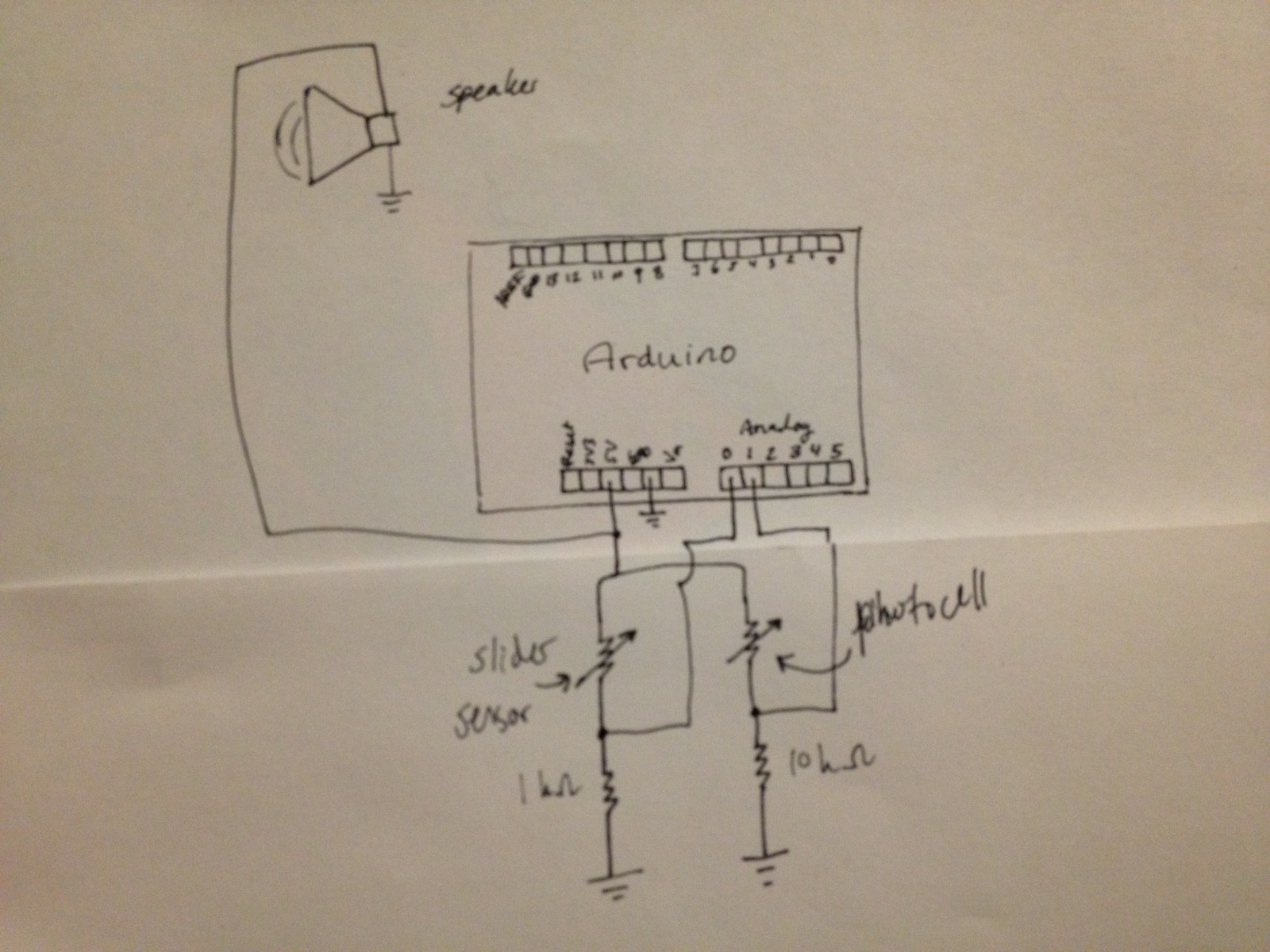
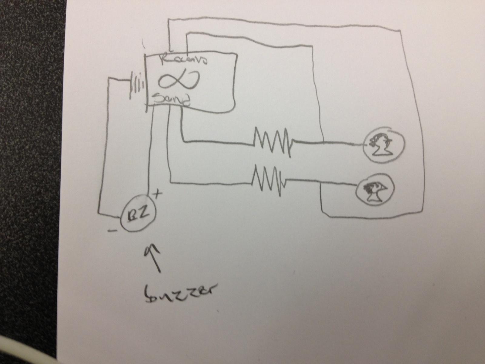
Instructions (image attached):

  1. Attach three buttons to breadboard, spaced comfortably apart.
  2. Attach a pulldown resistor between each of the buttons and ground.
  3. Connect ground to Arduino.
  4. Attach 5V line to the other side of the buttons.
  5. Attach signal lines between the resistors and buttons and run to digital pins 6, 8, and 10 on the Arduino.
  6. Attach potentiometer to Analog 0, ground, and 5V
2013-03-06 23.01.43

Reference Image for Circuitry

Source Code:
buttons.ino

#include 

int b1 = 6;
int b2 = 8;
int b3 = 10;
int b1Reading;
int b2Reading;
int b3Reading;
int curReading;
int lastReading;
int potPin = 0;
int fixed;

void setup(void) {
  MIDI.begin(0);
  Serial.begin(9600);
  pinMode(b1, INPUT);
  pinMode(b2, INPUT);
  pinMode(b3, INPUT);
}

boolean b1Last = false;
boolean b1New = false;
boolean b2Last = false;
boolean b2New = false;
boolean b3Last = false;
boolean b3New = false;

void loop(void) {
 
curReading = analogRead(potPin);
if (abs(curReading - lastReading) > 2) {
  fixed = map(curReading, 0, 1023, 0, 250);
  Serial.print("p");
  Serial.print(fixed);
   Serial.println(" ");
}

lastReading = curReading;
b1Reading = digitalRead(b1);
if (b1Reading == HIGH) { 
  b1New = true;
}
else {b1New = false;}

b2Reading = digitalRead(b2);
if (b2Reading == HIGH) { 
  b2New = true;
}
else {b2New = false;}

b3Reading = digitalRead(b3);
if (b3Reading == HIGH) { 
  b3New = true;
}
else {b3New = false;}

if( !b1Last && b1New) {
  Serial.println("1 ");  
}
if( !b2Last && b2New) {
  Serial.println("2 ");  
}
if( !b3Last && b3New) {
  Serial.println("3 ");  
}
b1Last = b1New;
b2Last = b2New;
b3Last = b3New;

delay(5);
}

beatlooper.ck

Shakers inst[16];
int filled[16];
0 => int count;
.125::second => dur step;
for(0 => int i;i  dac;
}
// create our OSC receiver
OscRecv recv;
// use port 6449
6449 => recv.port;
// start listening (launch thread)
recv.listen();
recv.event( "set, i" ) @=> OscEvent set;
<<>>;
fun void play() {
    while(true){  
        
        if(filled[count] == 1) {
            .9 => inst[count].energy;
            .8 => inst[count].noteOn;
            <<>>; 
        }
        step => now;
        if(filled[count] == 1) {
            .8 => inst[count].noteOff;
        }
        (count + 1) % 16 => count;
    }   
}
spork~ play();
while(true) {
    
    set => now;
    set.nextMsg();  //loop thing?
    1 => filled[count];
    set.getInt() => inst[count].preset;
    
    <<>>;   
}

looperknob.py

import serial
import OSC
import time

ser = serial.Serial('/dev/tty.usbmodemfa141', 9600)

client = OSC.OSCClient()
client.connect( ('127.0.0.1', 6449) )  
iset = OSC.OSCMessage()
iset.setAddress("set")
knob = OSC.OSCMessage()
knob.setAddress("knob")


while 1:
    line = ser.readline()
    if " " in line:
        if("p" in line):
            s = line.replace("p", "")
            print int(s)
            knob.append(int(s))
            client.send(knob)
            knob.clearData()
        else:
            print int(line)
            iset.append(int(line))
            client.send(iset)
            iset.clearData()

L2: Expressive Chaos

Krithin Sitaram (krithin@)
Amy Zhou (amyzhou@)
Daniel Chyan (dchyan@)
Jonathan Neilan (jneilan@)
Thomas Truongchau (ttruongc@)

Group 11

Expressive Chaos
Video Link
We built an instrument that combines multiple sensors that provides a unique experience for a performer to produce multiple sounds. We decided upon this design in order to challenge ourselves to use every sensor on the parts list and we believe we were successful in constructing this instrument. The final product does look a bit messy and it would be better if we had an enclosure in order to have a more pleasant looking instrument.

Instructions to Build:
Use 2 breadboards. On one breadboard, put flex sensor on the other breadboard, place the slide sensor, light sensor, and the button. The flex sensor, light sensor, and button are connected through pull-down resistors of 10k Ohms, 330 Ohms, and 330 Ohms respectively. Each are connected to an analog input pin.

Source Code:

const int INPINS[] = {A0, A1, A2, A3};
const int MAXVALUES[] = {950, 400, 1023, 320};
const int MINVALUES[] = {610,0,0,140};
const int BUZZER = 8;

void setup() {
  pinMode(BUZZER, OUTPUT);
  Serial.begin(9600);
}

void loop() {
  for (int i = 0; i < 4; i++) { // hardcoded len(INPINS);
    double outtone = (analogRead(INPINS[i]) - MINVALUES[i]) * ((double)1000/(MAXVALUES[i] - MINVALUES[i])) + 440;
    tone(BUZZER, outtone, 100);
    Serial.println(analogRead(INPINS[i]));
      Serial.println(outtone);
    delay(130);
    noTone(BUZZER);

  }
  Serial.println();
  Serial.println();

}

Prototype 1: Expressive Maraca
Video Link
This instrument simulates a maraca electronically using an accelerometer and buzzer.

Source Code:

#include <Math.h>

const int groundpin = A2; // analog input pin 2
const int powerpin = A0; // analog input pin 0
const int xpin = A5; // x-axis of the accelerometer
const int ypin = A4; // y-axis
const int zpin = A3; // z-axis 
int BASELINE; // baseline for accelerometer

void setup()

{
 Serial.begin(9600);

 pinMode(groundpin, OUTPUT);
 pinMode(powerpin, OUTPUT);
 digitalWrite(groundpin, LOW); 
 digitalWrite(powerpin, HIGH);
 BASELINE = analogRead(xpin);

}

void loop()
{

 Serial.print(analogRead(xpin));  // print the sensor values:
 Serial.print("\t");  // print a tab between values:
 Serial.print(analogRead(ypin));
 Serial.print("\t");   // print a tab between values:
 Serial.print(analogRead(zpin));
 Serial.println();
 delay(5); // delay before next reading:

 double diff = fabs(analogRead(xpin) - BASELINE);
 if (diff > 150) {
    tone(10, 440);
    delay(10);
    noTone(10);
 }

}

Prototype 2: Expressive Siren
Video Link
This instrument produces a siren sound with an accelerometer and buzzer.

Source Code:

#include <Math.h>

const int groundpin = A2; // analog input pin 2
const int powerpin = A0; // analog input pin 0
const int xpin = A5; // x-axis of the accelerometer
const int ypin = A4; // y-axis
const int zpin = A3; // z-axis 
int YBASELINE; // baseline for accelerometer
int XBASELINE; 

void setup()

{
 Serial.begin(9600);

 pinMode(groundpin, OUTPUT);
 pinMode(powerpin, OUTPUT);
 digitalWrite(groundpin, LOW); 
 digitalWrite(powerpin, HIGH);
 XBASELINE = analogRead(xpin);
 YBASELINE = analogRead(ypin);
}

void loop()
{
 double xchange =  fabs(analogRead(xpin) - XBASELINE); 
 double ychange =  fabs(analogRead(ypin) - YBASELINE); 
 double diff = sqrt(xchange*xchange + ychange*ychange);

 double ytone = (analogRead(xpin) - 272) * (440/137) + 440;
 Serial.println(ytone);
 tone(10, ytone);

}

int roundToTenth(double a) {
  double t1 = a / 10;
  double t2 = floor(t1) * 10;
  Serial.print(t2);
  Serial.println();
  return t2;

}

Prototype 3: The Metronome (which becomes Expressive Chaos)
Video Link
This metronome turns into our Expressive Chaos instrument.

Source Code:

const int INPINS[] = {A0, A1, A2, A3};
const int MAXVALUES[] = {950, 1023, 1023, 320};
const int MINVALUES[] = {610,0,0,140};
const int BUZZER = 8;

void setup() {
  pinMode(BUZZER, OUTPUT);
  Serial.begin(9600);
}

void loop() {
    tone(BUZZER, 440, 100);
    delay(1000);
    noTone(BUZZER);

}

Parts List for Expressive Chaos
– 1 Flex Sensor
– 1 Slide Sensor
– 1 Photocell
– 2 Resistors – 330 Ohms
– 1 Resistor – 10k Ohms
– 1 Buzzer
– 1 Button
– 2 Breadboards
– Arduino

L2: Sensor Cymbals!

Group Name: VARPEX

Group Number: 9

Group Members: Abbi Ward, Dillon Reisman, Prerna Ramachandra, Sam Payne

Prototype 1 (The Dog Toy Instrument):

For our first prototype, we use a force sensitive resistor to build a toy that a dog can bite at various places and create music. The force of the bite determines the tone of the music.

Prototype 2 (The Roll-Instrument)

For our second prototype, we use an accelerometer continuously maps the y-coordinate to a unique frequency of the tone that to create music when we roll the instrument.

Prototype 3 (The Clapper)

For our third prototype, we built a clapper that uses a light sensor to adjust the speed of beats based on the amount of light that reaches it through the plates, hence creating music.

We decided to refine our clapper to build a more playable, intuitive instrument.

Project Description:

Our musical instrument uses light to control the tempo of notes that have a pitch set by a user’s sliding finger. In our prototype of the light mechanism we found that the use of light gave the player a surprising amount of control over the sound produced, and could perform interesting, simple beats without even controlling pitch. This mechanism worked by placing a light sensor in a ‘clamshell’ that could be opened or closed- more light to the sensor created a faster beat, while a closed clamshell resulted in a slower beat. For our refined model, we have two black acrylic panels- one with the light mechanism attached, and another with the slider sensor for pitch-control. The player holds each piece in a hand and can pivot, rotate, pull away, or cover up the light sensor on one piece using the other piece. We chose this design because it gave the player two dimensions of sound to control in a very fluid, three dimensional way. In a future revision of this design we might want to give the user more control over the beat, such as the ability to have no beat (right now, the beat is, when the light sensor is completely covered, very slow, but not off).

Schematic

schematic

Project Demo

List of Parts

A list of parts used in your final system

  • Arduino
  • 1k-Ohm resistor
  • 10k-Ohm resistor
  • slider sensor
  • photocell
  • buzzer (speaker)
  • dead battery (This keeps the acrylic pieces from crushing the photocell and provides a pivot point for the pieces to rotate)
  • 2 pieces of acrylic
  • electrical tape to attach the battery to the acrylic

Instructions to Recreate System

Build the given schematic using alligator clips to attach the sensors. Tape the dead battery to one of the acrylic pieces — cover up the terminals. Carefully bend the leads of the photocell and rest it on top of the battery, parallel to the acrylic. Tape the slider sensor to one side of the other piece of acrylic. Load the Arduino code. Use the piece of acrylic with the slider sensor to cover the photocell and change the beat. Change the position of your finger on the slider sensor to change the tone.

Source Code

/*
Names: Dillon R, Prerna R, Sam P, Abbi W (Group 9)
Date: 3/2/13
Class: COS 436 - L2
For a musical instrument using the photocell and slider sensor. 
Light makes a faster beat and the slider corresponds to a scale
*/
// Pins
int sliderPin = A0;
int lightPin = A1; 
int speakerPin = 9;
int sliderValue;
int lightValue;
int tempo = 330;
int beat;
// sensor value ranges
int lightRangeLow = -1*200;
int lightRangeHigh = -1*950;
int sliderRangeLow = 100;
int sliderRangeHigh = 550;
void setup(){
 pinMode(speakerPin, OUTPUT);
 Serial.begin(9600);
}
void loop() {
 sliderValue = analogRead(sliderPin);
 lightValue = analogRead(lightPin);
 Serial.println(lightValue);
 //char note = setNotefromSlider(sliderValue); 
 setBeat(-1 * lightValue);
 playNote(setNote(sliderValue),tempo); 
 delay(tempo/2); 
}
// varies the tempo
void setBeat(int sensorValueA) {
 // for reading light sensor
 tempo = map(sensorValueA, lightRangeHigh, lightRangeLow, 5, 800); 
}
// sets a note c to C based on the slider position
char setNote(int sensorValue) {
 /* sensor value is 100 to 550 */
 int readVal = map(sensorValue, sliderRangeLow, sliderRangeHigh, 0, 830);
 int cmax = 180;
 int dmax = cmax+100;
 int emax = dmax+100;
 int fmax = emax+100;
 int gmax = fmax+100;
 int amax = gmax+100;
 int bmax = 780;
 if (sensorValue < cmax) {
 return 'c';
 }
 if (sensorValue < dmax) {
 return 'd';
 }
 if (sensorValue < emax) {
 return 'e';
 }
 if (sensorValue < fmax) {
 return 'f'; 
 }
 if (sensorValue < gmax) {
 return 'g'; 
 }
 if (sensorValue < amax) {
 return 'a'; 
 }
 if (sensorValue < bmax) {
 return 'b'; 
 }
 return 'C'; 
}
// method from Arduino tutorial
void playTone(int tone, int duration) {
 for (long i = 0; i < duration * 1000L; i += tone * 2) {
 digitalWrite(speakerPin, HIGH);
 delayMicroseconds(tone);
 digitalWrite(speakerPin, LOW);
 delayMicroseconds(tone);
 }
}
// method from Arduino tutorial
void playNote(char note, int duration) {
 char names[] = { 'c', 'd', 'e', 'f', 'g', 'a', 'b', 'C' };
 int tones[] = { 1915, 1700, 1519, 1432, 1275, 1136, 1014, 956 };
// play the tone corresponding to the note name
 for (int i = 0; i < 8; i++) {
 if (names[i] == note) {
 playTone(tones[i], duration);
 }
 }
}


L2: Coin Chime

Group Name: %eiip

Group members: Mario Alvarez (mmcgil@), Bonnie Eisenman (bmeisenm@), Erica Portnoy (eportnoy@), Valya Barboy (vbarboy@)

What we built: We built a “coin chime” — a small, windchime-like instrument using a bunch of quarters and alligator clips. Some of the quarters act as proximity sensors; when they come near the other quarters (or even better, touch), they send a signal to the Arduino, which in turn causes the buzzer to make noise based on this input. We built this because we thought that windchimes are cool, and somewhat unconventional in terms of “musical instruments.” We really like our result; it’s fun to play with, even though it’s difficult to intentionally produce “music.” If we were to improve upon our design we would probably add more proximity-sensing coins (currently there are only two), and we would probably refine the code that determines what sounds are played to make it more closely mimic a set of chimes. We also would like to experiment with the proximity sensors; using the code provided, if the delay between readings is too short the sensors don’t function correctly.

Erica using the coin chime. Above, you can see the setup, including the Arduino and buzzer.

The final setup: a bunch of quarters hanging from alligator clips, an Arduino, and a buzzer. The coin pouch keeps the quarters in place. Two of the quarters are proximity sensors.

Prototype 1: Gong with Piezo.

Building the prototype of our “gong,” using the Piezo and a paper plate.

Our first prototype is a “gong”-style instrument using a Piezo. The Piezo detects vibration, and then based on the level of vibration, a short program instructs the buzzer to sound.

Prototype 2: 

We call our second prototype the “Shakey.” It creates noise using a buzzer depending on how much you shake it (which is measured using the accelerometer). The noise is pseudorandom.

Prototype 3:

This is an early version of our coin chime. The first coin is a proximity sensor; we were testing what threshold was necessary for it to sense the second coin somewhat reliably. When the proximity sensor’s output passes a certain level, the buzzer sounds.

List of Parts:

  • ~12 Quarters
  • 1 Arduino
  • 2 10 Megaohm Resistors
  •  Wires
  • Alligator clips
  • 1 Buzzer
  • 1 USB cable
  • 1 Breadboard

Instruction for Recreation:

Circuit diagram for Coin Chime

Using the above diagram, recreate the circuit; the resistors pictured should be 10 megaohm resistors, and the two circles connected to them are quarters. The quarters should be connected using alligator clips or something similar, so that they can be dangled off of a ledge. Then, attach a bunch of other quarters to alligator clips and dangle them together with the two proximity-sensing quarters. (The extra quarters needn’t be connected to the circuit.) Finally, load up the code below, and start playing with your coin chime! Optional modifications include adding extra proximity-sensing quarters.

Source code:


#include 
int speakerPin = 9;

CapacitiveSensor   cs_4_2 = CapacitiveSensor(4,2);       
CapacitiveSensor cs_13_12 = CapacitiveSensor(13,12); 

int tempo = 300;

void playTone(int tone, int duration) {
  for (long i = 0; i < duration * 1000L; i += tone * 2) {
    digitalWrite(speakerPin, HIGH);
    delayMicroseconds(tone);
    digitalWrite(speakerPin, LOW);
    delayMicroseconds(tone);
  }
}

void playNote(char note, int duration) {
  char names[] = { 'c', 'd', 'e', 'f', 'g', 'a', 'b', 'C' };
  int tones[] = { 1915, 1700, 1519, 1432, 1275, 1136, 1014, 956 };

  // play the tone corresponding to the note name
  for (int i = 0; i = thresh && total2 >= thresh) {
    playNote('b',tempo);
  }
  else if (total1 >= 900) {
    playNote('C',tempo);
  }
  else if(total2 >=900) {
    playNote('a',tempo);
  }
  // Make the delay too short, and the proximity
  // sensors won't work. :(
  delay(50);
}