L3 — All Terrain Strugglebot

Members of the Illustrious Group #21: “Dohan Yucht Cheong Saha”

  • Miles Yucht

  • David Dohan

  • Andrew Cheong

  • Shubhro Saha


Short Description

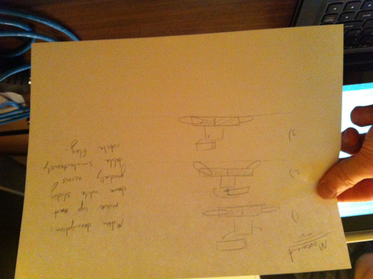
This week we were in a Southern mood in anticipation of Spring Break, so we initially decided to build a LassoBot. This robot throws a lasso in a circle until an object in the lasso’s path is grabbed on to. At that point, LassoBot reels itself closer to the object it caught. Late in development, we realized that making LassoBot hook itself onto stationary was extraordinarily difficult given the weakness of the DC motor. At that point, we switched to building a StruggleBot that constantly rotates a lasso in an effort to move forward in a particular direction. The final product was a great success. The StruggleBot is amusing to watch, as it struggles, and it’s a creative means of locomotion. There were a few initial difficulties while creating our robot.  Our initial plan to create a lasso bot did not work because the DC motors are too weak to reliably pull the robot along (although it did work in some cases).  Additionally, it was difficult to spin up the lasso without it tangling with itself.  Other plans for the “tumble weed” robot fell through because we found that the Arduino is incapable of adequately powering four servo motors simultaneously as required.


Idea Brainstorm

  1. A snake like robot that moves by curling and uncurling

  2. Attach random objects to it and watch it go berzerk

  3. Flying robot that has rotor blade attached underneath

  4. Moves with caterpillar treads made of… banana peels? Newspaper?

  5. Two-wheeled robot, kinda like a segway, but without the balancing complexity

  6. A robotic “hand” that drags itself across the table, as in Toy Story

  7. A robot that throws a lasso rope and rolls the rope to pull itself closer to the hitched destination

  8. A motorboat! Moves across water, obviously

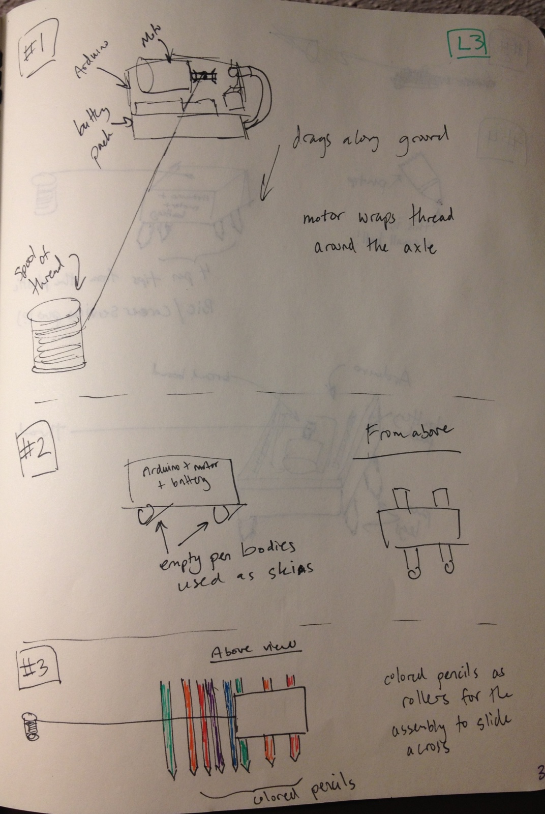
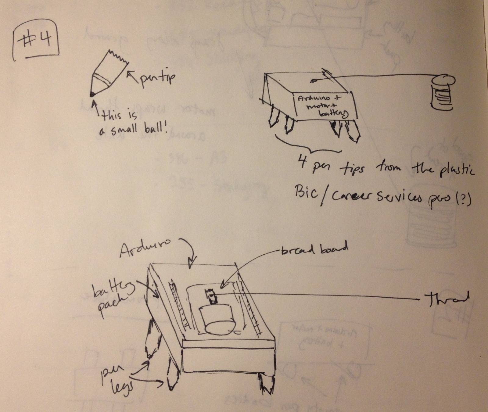
  9. A robot that pulls itself up a table/wall by raveling a spool of rope hanging from a point… like a cliffhanging robot… even attach a person to make it look creative

  10. Slinky robot, that can move up a staircase by throwing a hook onto the next stair

  11. Window-climbing robot… give it suction cups to go up a window

  12. Shufflebot… by design, it rolls 2 steps forward, 1 step back

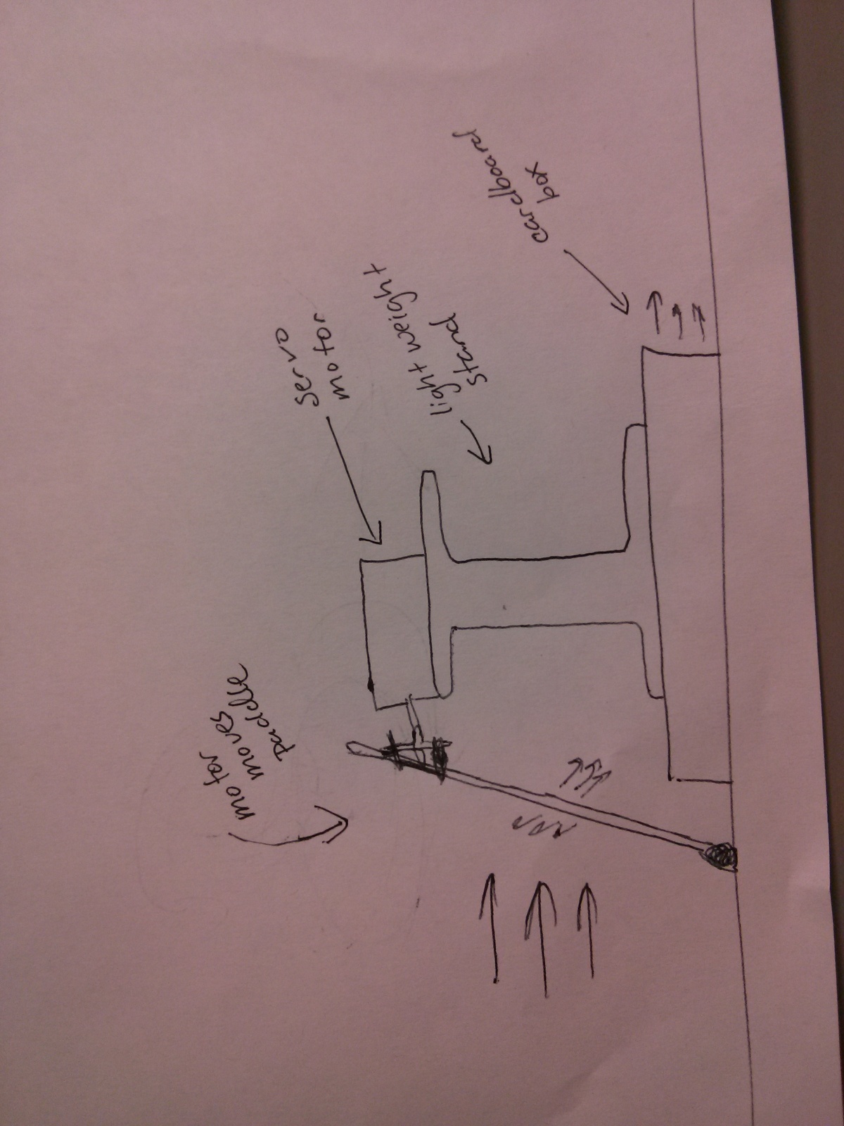
  13. Tumbleweed bot.  Looks like a hamster wheel, but has servo motors attached around the edges to roll it forward.  Alternatively, have a single servo motor and a counterweight at the center.
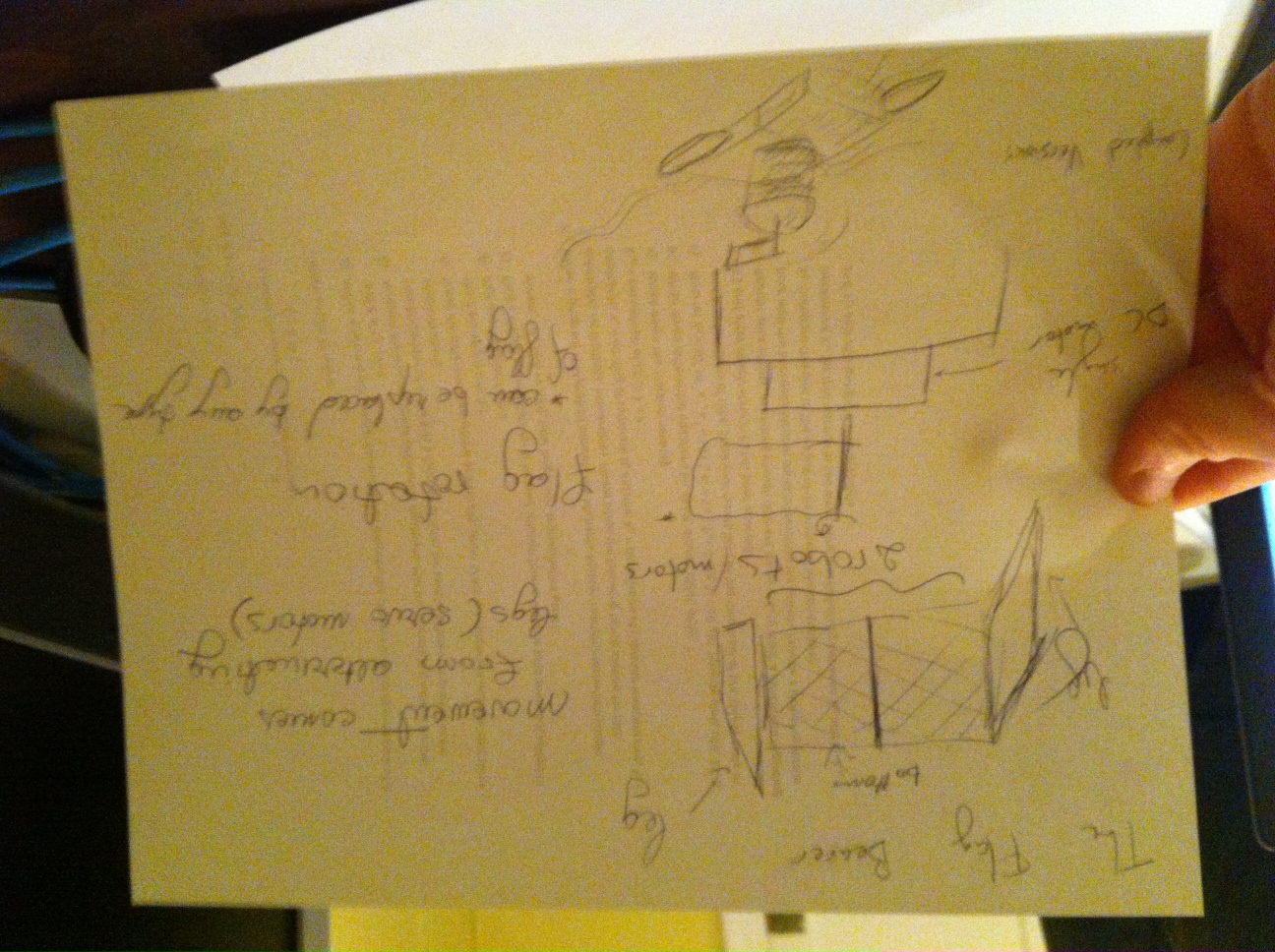
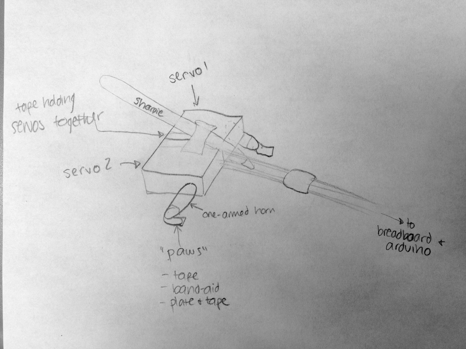
 

Design Sketches


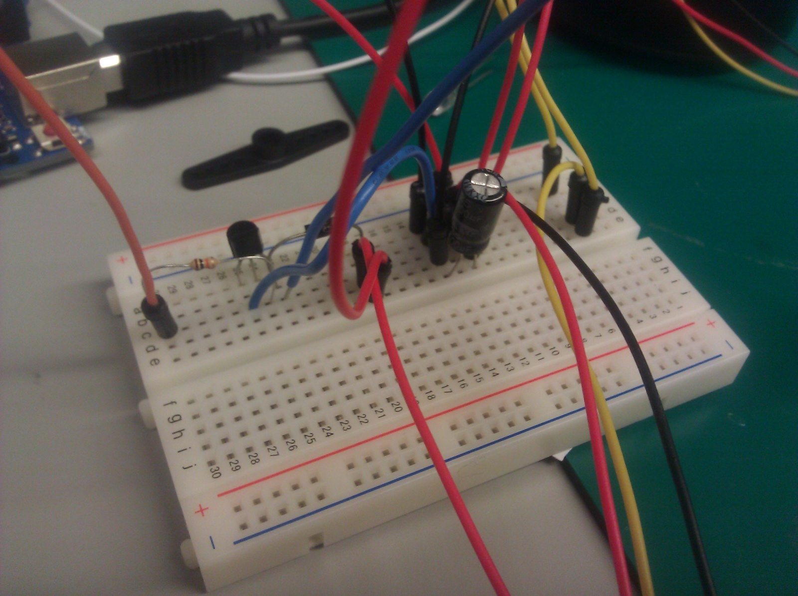
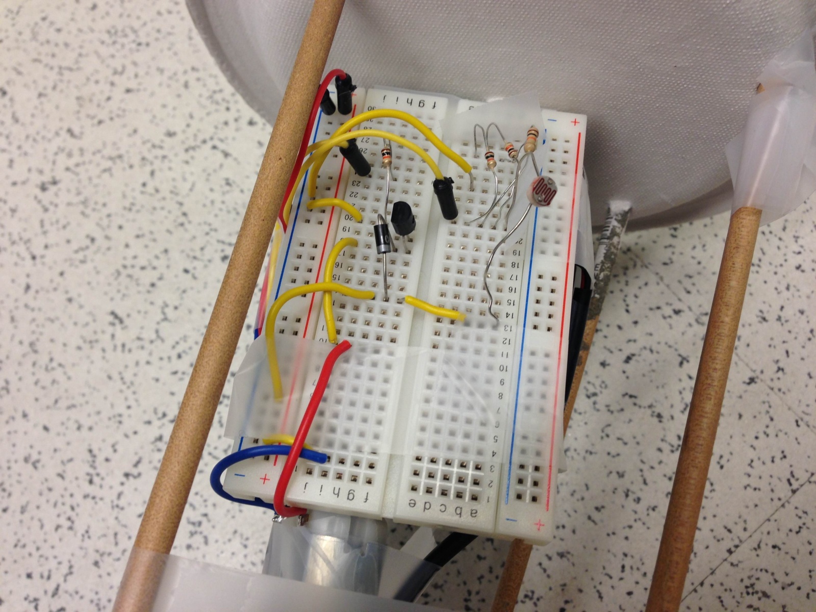
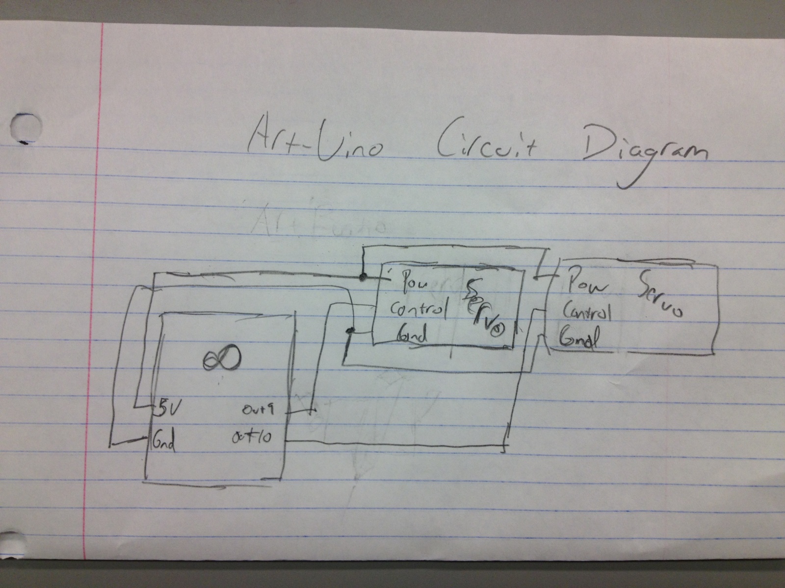
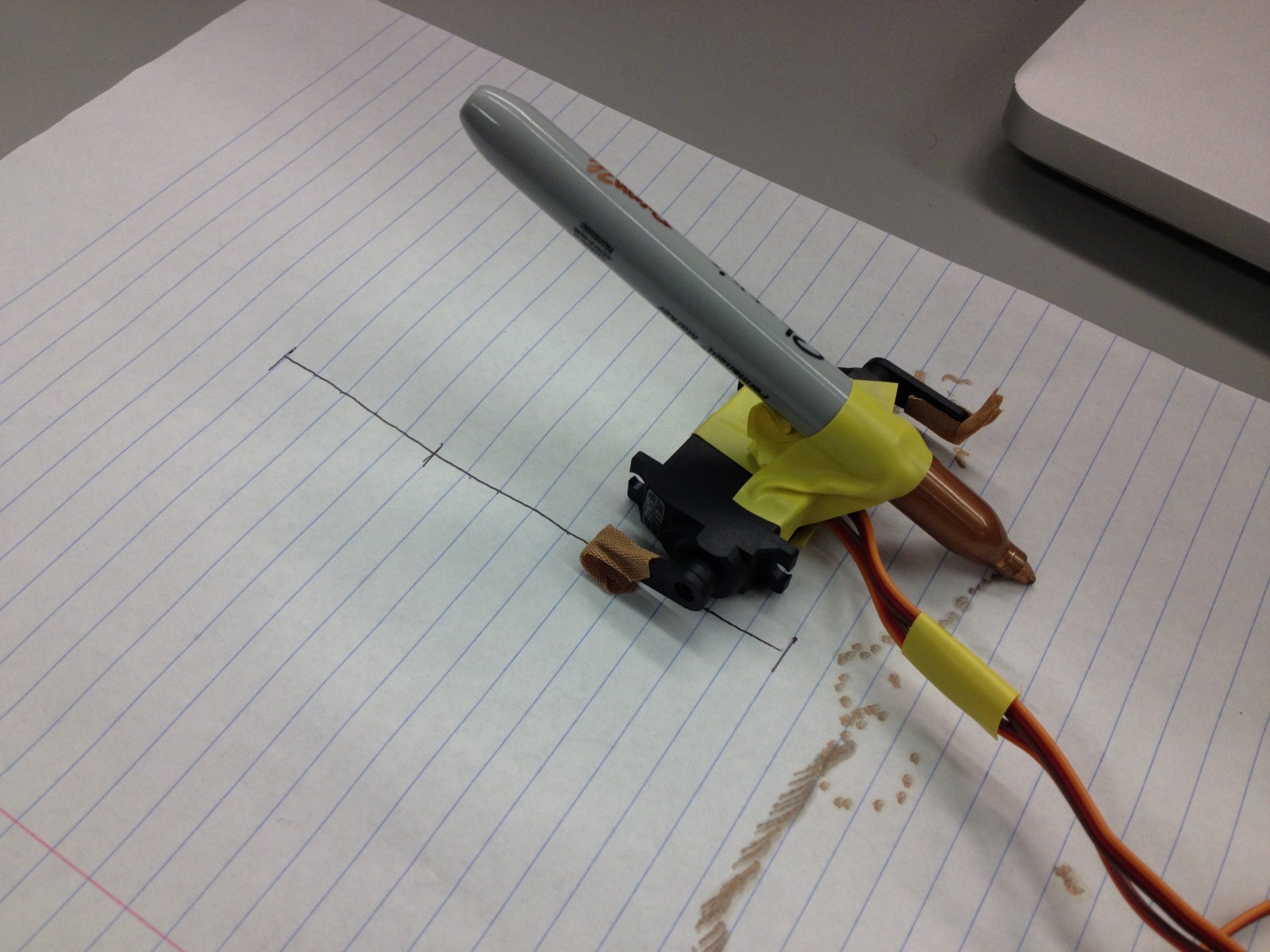
Final Schematic of Strugglebot


Final System Video


List of Parts

1 AC motor

1 330-ohm resistor

1 potentiometer

1 zener diode

1 PN2222 transistor

2 jumpers

1 6-inch length of string

1 inch of wire

1 Arduino UNO

Electrical tape


Assembly Instructions

1. Set up the potentiometer element to control the rate of rotation of the motor. Connect pin 1 with +5V, pin 2 with A0 on the Arduino, and pin 3 to ground.

2. Set up the motor circuit. To pin 3 on the Arduino, connect a 330-ohm resistor, and connect this to the base on the transistor. Connect the emitter to ground. Connect the motor in parallel with a Zener diode, and connect both of these elements in series with the collector.

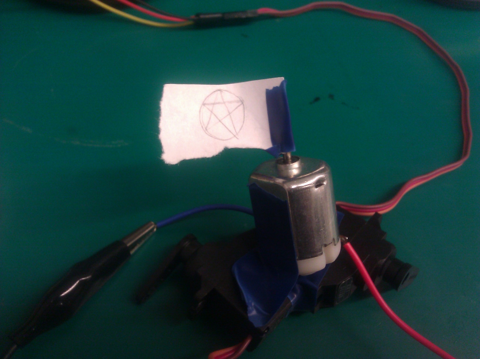
3. Mount the motor on the bottom of a circuit board using electrical tape, and use two jumpers in the circuit board to elevate the circuit board off of the ground, face down. Make sure the motor is inclined at 45 degrees.

4. Attach a thread to the motor using tape, and to the other end of the thread attach a piece of wire bent into a hook shape.

5. Upload the code, and use the potentiometer to control the rate of rotation.

Final Source Code

int motorPin = 3;
void setup() {
pinMode(motorPin, OUTPUT);
analogWrite(motorPin, 255);
}
void loop() {}

Group VARPEX – L3

Names: Abbi Ward, Dillon Reisman, Prerna Ramachandra, Sam Payne

Group Number: 9

Description

For this lab we built a robot with four legs that pulls itself along a string. Its four legs are the tips of ballpoint pens, allowing for a smooth gliding motion on relatively frictionless surfaces. Our original inspiration for the robot came from an idea we had to build a robot that opened and closed window shades according to how much light was in a room. This robot would move vertically rather than horizontally, doing so by using a motor to pull itself up a string. We decided to test this method of locomotion horizontally first. We were very pleased with the success of our robot- we did not imagine that it would move so well over the table surface, and in future iterations of this robot we could have it do interesting things in how it moves. The ballpoint pen tips were extremely useful tools for motion along a surface. Unfortunately we do not think the method we used to collect the string once the robot pulled it worked well (we simply wind it up on the end of the motor), and in future iterations we think that the robot should have a way of going one direction on the string, then reversing the motor and going the other direction. In total, however, we think that this method of motion could have many applications.

Brainstormed Ideas: 

  1. Helicopter using paper/cardboard blades
  2. Vibrating robot, moves by vibration
  3. Robot on wheels which uses a fan to propel itself
  4. Arms which rotate similar to single blade propellers to promote movement
  5. Three-legged omnidirectional single plane robot
  6. Worm robot, uses a single joint to contract and move forward
  7. Robot that hits the ground hard enough to “jump” forward
  8. Move the motor foward and reverse direction to hit limbs against ground and propel forward
  9. Use servo to wiggle from side to side and move forward
  10. Robot which eats tape/line of string to move forward
  11. Robot which dances to a beat
  12. High five Robot – moves up to you and gives you a high five if you bring your hand close to it
  13. Acrobat robot – does flips at regular intervals as it moves around in a circle

We chose to prototype Idea 10, a robot which eats a line of string to move forward.

Design Sketches

sketch-1

Assembling the robot, use of the string and using pencils to reduce friction

sketch-2

Using only pencil tips to minimize ground friction, instead of rolling pencils

Demo of our System

Parts list

  • Arduino
  • motor
  • PN2222A transistor
  • Diode (1N4001)
  • electrical tape
  • 4 disposable ballpoint pens (plastic)
  • breadboard
  • 330 ohm
  • battery pack to power the Arduino

Instructions to Recreate System

  1. Build the schematic on the breadboard
  2. Attach the motor to the breadboard with electrical tape

  3. Break open one of the disposable pens into the following parts

    1. the outer tube

    2. inner tube (holds the ink)

    3. tip

    4. ink

  4. Cut off about a 1/2 inch of the inner tube that doesn’t have any ink

  5. Use thinly sliced strips of electrical tape to make ridges on the edges of the tube. This will be used to help keep the thread on the axle so that the robot pulls itself and the thread will not rub against the base of the motor.

  6. Push this tube+tape combo onto the axle of the motor so that it fits snugly.

  7. If leads are showing on the bottom/sides of the battery pack, put electrical tape over them so that loose wires don’t accidentally short power and ground.

  8. Tape the Arduino to the battery pack (the batteries should face the floor)

  9. Cut up the outer tube into ~1 inch pieces and place them on the Arduino.

  10. Tape the breadboard+motor on top of the pen pieces such that the axle of the motor is centered on the robot.

  11. On each of the four pens, take off the tips (with the ink cartridge removed) and tape them to the side/bottom of the battery pack such that the assembly balances and can slide easily across the floor or table.

  12. Use a small piece of electrical tape to attach the thread piece

  13. Hold the spool, upload the code, and the robot will traverse towards the spool

Source Code for the Robot

/*
Names: Dillon R, Prerna R, Sam P, Abbi W
Group 9, Varpex
COS 436 S2013
Our robot code. 
This was just for walking across the table. 
*/

int motorPin = 3;

void setup() 
{ 
 pinMode(motorPin, OUTPUT);
} 

void loop() 
{ 
 int motorspeed = 254;
 //walk a little bit
 analogWrite(motorPin, motorspeed);
 delay(3000);
 // stop
 analogWrite(motorPin,0);
 while(1); 
}


Group 10: Lab 3

Group Number and Name

Team X – Group 10

Group Members

  • Osman Khwaja (okhwaja)
  • Junjun Chen (junjunc)
  • Igor Zabukovec (iz)
  • (av)

Description of System

We built a crawler that propels itself forward by “punting”. We were inspired by punt boats which are propelled by a punter pushing against the bottom of a shallow riverbed with a long pole. Our system works by having the crawler push against the surface of the table with a short pole (attached to a servo motor), sliding itself forward as a result. The crawler does not actually move in the direction that we expected to when we made it, and problem we had is that there was no way to do the equivalent of lifting the pole out of the water in order to bring it back to the initial position. However, these two problems combined resulted in a crawler that worked differently from how we first intended, but nevertheless managed to scuttle forward fairly effectively. To improve this, we might try mounting the servo motor on a wheeled cart, which would help its movement be more consistent with our intention.

Brainstorming

  1. Ballerina – DC motor that spins a pencil wearing something similar to a dress
  2. Rocking Chair – Uses servo motor to rotate between end positions, just like a rocking chair
  3. Unicycle – wheel surrounds a DC motor and the wheel rotates as the DC motor does
  4. Yarn Ball Retracer – DC motor spins up along a string and moves eventually until all the string is wound up again
  5. Waddle Walker – Uses the servo motor to awkwardly waddle/walk in a semi-straight line by alternating leg movements
  6. Log roller – DC motor attached to a log=shaped object that is connected to the spinning axle of the motor
  7. Reversed roller – DC motor spins a gear which is connected to an object that moves along the ground. The direction of rotation of the DC motor is reversed due to the gear connection, and the object rolls in the reverse direction
  8. Hamster Ball – A DC motor is attached to a wheel (or small ball) inside a ball (the wheel is not connected to the ball, but pushes it).
  9. Wheelbarrow – A DC motor moves the front wheels of the vehicle, but it only moves if something is holding up the back.
  10. Lurcher – A two legged robot, one leg is static and being dragged by the other, which takes steps using a servo motor.
  11. Propellor Robot: a robot on wheels that moves by using a propellor attached to the back that blows it along.
  12. Punt: We attach an punting pole to a servo motor, and have it in a wheeled cart. The motor pushes the pole into the ground periodically, pushing itself forward.

Sketches

Circuit Sketch (taken from Arduino tutorial on Servo Motors):
some_text


Crawler Sketch:

sketch


Demonstration Video

Parts Used

  • Servo motor
  • Arduino
  • Cardboard Arduino box
  • Empty spool (to raise servo motor)
  • Straws (for punting pole)
  • Electrical tape
  • Jumper wires

Instructions

  1. Tape the empty spool vertically onto the empty Arduino uno box.
  2. Tape the servo motor horizontally on top of the spool
  3. Fashion an oar out of some small sticks by taping them together. At one end of the oar (the base), create a round end with electric tape
  4. Tape the oar to the rotating part of the servo motor such that the oar will hit the ground during rotation. Attach the oar such that it provides forward locomotion by angling it away from the box.
  5. Connect the servo motor to the breadboard and the arduino as shown in the picture from the adafruit learning system tutorial
  6. Connect the arduino to power and let it propel forward

Source Code

#include <Servo.h>
int potPin = 0;
int servoPin = 9;
Servo servo;

int angle = 0;

void setup()
{
  servo.attach(servoPin);
}

void loop()
{
  angle++;              // 0 to 180-ish
  servo.write(angle);
}

L3 – Team Colonial Club

Team Colonial Club, Group #7

David Lackey
John O’Neill
Horia Radoi

Description

This robot tries to simulate walking using two servomotors attached to opposing sides of the body. It is using friction to thrust itself forward. .

This robot is a precursor to the infamous ATAT, present in the (good) episodes of the Star Wars saga. As opposed to the robot that helped conquer Hoth, our model uses only two legs, on opposing sides, and upon careful calibration, the device can walk. Since our project was struggling with this last step, we decided to add a flag on top of it and call it a marvel of Empire Engineering.

List of Brainstorming Ideas

  1. oscillating helicopter
  2. creature that moves until it finds a sunspot / light
  3. boat that submerges itself when it hears a sound
  4. tank creature (multiple motors within on tread)
  5. worm
  6. creature that travels by rapid, random vibrations
  7. hovercraft
  8. robot that quickly rotates a flag
  9. swimmer
  10. walks around while spinning a disco ball
  11. robot that goes slower in the cold
  12. samurai robot that twirls a staff (we could have two battle)
  13. tug of war robots, each moving away from one another

Photos of Design Sketches

photo 1 photo 2

Final System Media    

IMG_20130326_214035

Breadboard

IMG_20130326_213955

The creature, complete with flag

Creature
Video of Moving Robot Carrying Flag
Moves from point A to point B, ever so slowly…

List of Parts

  1. 1 arduino + jumper wires + usb connection/power
  2. 2 servo motors (for legs)
  3. 1 AC motor
  4. Electrical tape (to attach pieces together)
  5. Transistor
  6. Diode
  7. Capacitor
  8. 330 ohm resistor
  9. Arduino
  10. Custom flag to represent your team

Recreation Instructions

After acquiring the appropriate materials, wire the DC motor to digital pin 8 as well as two Servo motors to pin 9 (so that they move in conjunction with one another.) Next, tape together the two Servo motors as demonstrated in the video, then orient the DC motor with the pin facing upward and tape it to the two Servo motors (making sure to include your own personalized flag to the top of the DC motor.) Once these all of these components are assembled, upload the attached code and watch your creature strut its stuff!

Source Code

#include  

int servoPin = 9;
int motorPin = 8; 

Servo servo;  

int angle = 0;   // servo position in degrees 

void setup() 
{ 
  pinMode(motorPin, OUTPUT);
  servo.attach(servoPin); 
} 

void loop() 
{ 
  // scan from 0 to 180 degrees
  for(angle = 0; angle  0; angle--)    
  {                                
    servo.write(angle);        
    analogWrite(motorPin, 250);   
    delay(5);       
  } 
}

Team CAKE – Lab 3

Connie, Angela, Kiran, Edward
Group #13

Robot Brainstorming

  1. Peristalsis robot: Use servo motors with rubber bands to get it to move with elastic energy somehow
  2. Helicopter robot: spinning rotor to make it fly (like the nano quadrotor except less cool)
  3. Puppet robot: use motor or servos to control puppet strings
  4. Crab style robot: crawling on six legs
  5. Robo-ball: omnidirectional rolling
  6. 3- or 4-wheeled robot: like a car
  7. fixed magnitude offset in motor speed of 2-wheel robot — move in squiggles
  8. Magnet-flinging robot: has a string with a magnet attached to it, uses a motor catapult to throw it forward, latches on to nearest magnet, and then has another motor to reel in the string. rinse and repeat
  9. Flashlight-controlled robot: use photosensors and it only moves if a lot of light is shone on it
  10. Tank robot: use treads around wheels
  11. Hopping robot: uses a servo to wind up a spring and fling itself forward
  12. Inchworm robot: moves like an inchworm
  13. Sidewinder robot: moves like a sidewinder
  14. Hot air balloon: make a fan that blows air past a heated element into a balloon (might be unsafe)
  15. Sculpture: moves linked magnets in constrained area with a magnet on motor (more of an art piece than a robot)

Red light Green light Robot

Our robot is a two-wheeled vehicle made of two paper plates. It plays red light green light with the user: when the user shines a flashlight on the vehicle, it moves forwards. It stops moving when the light stops shining on it.
We made this because it was a simple way to make a robot that was still interactive, rather than just moving arbitrarily on its own. While our electronics worked exactly as planned, it was very difficult to create a chassis that would allow the motor to drive the wheels while being able to support the weight of the battery pack, arduino, and breadboard. In fact, our robot didn’t really work – it just shuddered slightly but didn’t move. This was primarily due to the weight of the components; we’d need a more specialized set of parts like Lego or some structural kit with gears instead of sticks, plates, and tape. It was especially difficult to find a way to connect the smooth motor shaft with the plate (although we did get a very good attachment with just one plate and a motor).

Here is a shot of our robot in action, or to be more accurate, robot inaction.

Here is a shot of our robot in action, or to be more accurate, robot inaction.

In this picture you can see the electronics as well as the attachments of the components and dowels to the wheels.

In this picture you can see the electronics as well as the attachments of the components and dowels to the wheels.

This is the design sketch for the Red light Green light robot

This is the design sketch for the Red light Green light robot

Parts List

  • Arduino Uno with battery pack
  • Breadboard (as small as possible!)
  • Wires
  • Photoresistor
  • PN2222 Transistor
  • 1x DC motor
  • 1x 1N4001 diode
  • 1x 270Ω resistor
  • 1x 3KΩ resistor
  • 2x paper plates
  • 1x photoresistor
  • Wooden dowel, at least 40cm long
  • Tape
  • Paperclips

Instructions

  1. Attach the photoresistor from 5V to analog pin 5 through a 3KΩ pulldown resistor
  2. Attach the motor as shown in http://learn.adafruit.com/adafruit-arduino-lesson-13-dc-motors/breadboard-layout; use the diode between the two sides of the motor, attaching the middle pin of the transistor to digital port 3 through the 270Ω resistor
  3. Measure the ambient light reading from the photoresistor, and then the flashlight reading, and set the threshold appropriately between the two readings
  4. Punch holes as appropriate in the paper plate wheels (small holes in the center, two larger ones opposite each other).
  5. Unfold a paperclip and wind one half around the spinning axle of the motor. Tape the other half flat on the outside of one wheel.
  6. Break the dowel in half and poke the halves through the larger holes in the wheels, tape them in place.
  7. Securely attach arduino, breadboard, and battery pack in a solid block. Connect the motor appropriately, and make sure the photoresistor faces upward.
  8. Unfold a paperclip and securely tape half onto the arduino/breadboard/batteries contraption. Unfold the other half and poke a straight prong through the paper plate not attached to the motor.

Source Code

/* Red light Green light robot
 * COS436 Lab 3, group 13
 */
int motorPin = 3;
int photoPin = A5;
int motorspeed = 0;
int threshold = 830;
 
void setup() 
{ 
  Serial.begin(9600);
  pinMode(motorPin, OUTPUT);
  pinMode(photoPin, INPUT);
} 
 
 
void loop() 
{
  Serial.println(analogRead(photoPin));
  if (analogRead(photoPin) > threshold) {
    motorspeed = 200;
  }
  else {
    motorspeed = 0;
  }  
  analogWrite(motorPin, motorspeed);
  delay(40);
} 

Art-duino

Group 18

Bonnie (bmeisenm@), Erica (eportnoy@), Mario (mmcgil@), Valya (vbarboy@)

Description

We built a mini-crawler robot that draws a path behind it to make interesting designs. We chose this design for a variety of reasons. First and foremost, we experimented with attaching our other materials to the motors, and most of them were too heavy for the motors to handle. In particular, we wanted to use the DC motor to drive a wheel, but all materials were too heavy for it. For this reason using the slinky or other toys was not an option. We also liked the idea of combining the two servos to make legs, and adding the marker on top was interesting because we could visually track even minimal movement. In the end, we liked the cool random patterns that our Art-duino made. That being said, it moves more slowly than we would have liked, because it was very difficult to deal with the friction and the lack of forward power. Because the servos can only turn 180 degrees, we had to find some way to allow the arms to reset to their original positions, without moving the Art-duino backwards. Our solution to this were the “paws” (see sketch), which were good at battling the friction, but not too great. Since the two servos push the bot alternately forward and backwards, the paws create an asymmetry by increasing the force due to friction in the forward direction. We also wish we could make the motion more deterministic, although the randomness creates cool images.

Brainstorming

  1. We have an android doll. We could put cardboard underneath, and give it wire spools to make it roll.
  2. We have a string of beads which turns, and whatever is at the end of the chain is the robot, like a puppy!
  3. String of wire, with a motor attached to one end, as it winds the spool the robot will climb, like a spider!
  4. We have a little music box. Our robot would have a piezo sound sensor, and it would move when it heard music.
  5. A little reptile-robot that spins around until it finds light, and then crawls towards the light.
  6. Slinky-robot that dances to the music, by flipping and flopping around.
  7. Max (from Where the Wild Things Are) can come bring you a flower, on his little cardboard boat.
  8. A robot that runs away when it senses vibrations (for example, stomping).
  9. A maze of cards that the robot moves through. It does this by trying to go forward, and if it can’t do so it turns 90 degrees and continues.
  10. A robot that doesn’t like to be touched: it runs away from your hand, using a proximity sensor.
  11. A robot that moves in random patterns due to vibrations caused by an imbalanced motor.
  12. A mecha robot that walks upright using servos to move its legs.

Design sketches

A sketch of Art-duino

The circuit diagram for our final design.

Art-duino’s final form.

Video

This video shows the tape-pawed prototype of Art-duino in action, along with earlier prototypes and experiments to make the crawler move.

Parts List

  • 2 servos
  • 2 one-armed horns
  • paper plate
  • sharpie
  • electrical tape
  • wires
  • breadboard
  • Arduino

Instructions

First use electrical tape to connect the two servos. The wires should both be in the middle, facing forward. Connect the one-armed horns so that they sweep in opposite directions. Connect this to your Arduino, as indicated in the circuit diagram. Cut a tiny bit off of the paper plate, to make the paws, and tape them so that the paw faces forward (like a dog), and so that they are completely covered with tape. Then attach a sharpie (facing backwards), so that the robot draws as it walks.

Source Code

/*
Based on Adafruit Arduino - Lesson 14. Sweep
*/

#include <Servo.h>

int servoPin = 9;
int servoPin2 = 10;

Servo servo;
Servo servo2;

int angle = 0;   // servo position in degrees

void setup()
{
    servo.attach(servoPin);
    servo2.attach(servoPin2);
}

int speed1 = 0;
int speed2 = 0;
void loop()
{
    // scan from 0 to 180 degrees
    for(angle = 0; angle < 180; angle++)
    {
        servo.write(angle);
        servo2.write(angle);
        delay(5);
    }

    // now scan back from 180 to 0 degrees
    for(angle = 180; angle > 0; angle--)
    {
        servo.write(angle);
        servo2.write(angle);
        delay(5);
    }
}