GaitKeeper P4

a) Group 6 – GARP

b) Rodrigo, Alice, Gene, Philip

c) Our product, the GaitKeeper, is an insole pad that can inserted into a shoe, and an associated device affixed to the user’s body, that together gather information about the user’s gait for diagnostic purposes.

di) To get informed consent, we attempted to be as open to our participants as possible in the informed consent script. We told them how long the tests would take, the purposes that they would be used for and that they could leave at any time. We made sure to tell them the tests would be confidential and after telling them about any risks (inbalance, etc), we made sure to ask them again if they wanted to try it on. The consent script we used can be found here:

https://docs.google.com/document/d/15_Pr3GMbCt_wpIf99z1IczYtpQ5kbLyjgGjK6-hTLoo/edit?usp=sharing

dii) Our first participant is an avid runner and friend. He was selected because we know his passion for running. Also, we could easily schedule an observation time for the test.

Our second participant is also an avid runner, who competed on  his high school running team. He also has computer science experience, and therefore can help us evaluate our user interface.

Our third participant is an avid marathon runner. She has experience with injuries from running.

diii) The testing environment for the first task, the first half of the second task, and the entire third task is Stephens Fitness Center. We selected a time of low-use, to make sure we could communicate easily without an excess of noise and distractions. We will be using a treadmill for these portions.

The testing environment for the analysis portion of the second task will be a desk in a classroom or dorm room where we will place the “computer” for connection to the GaitKeeper.

For the third task, we will bring several pairs of our own shoes of the appropriate sizes.

div) First, Rodrigo read out the informed consent script. Then, Gene read out the demo script and the tasks script. In the second task, Alice played the role of the injured athlete and in the third task, Philip played the role of the shoe customer.

Demo Script:

https://docs.google.com/document/d/1qdcM1-UMU7VAQ6O4MlqqTKEbhYnxkzGOEwVxUrn7HJA/edit?usp=sharing

e) One of the biggest pieces of feedback we received is that the prototype is a little obtrusive for running. Some runners already remarked that having weight on one leg, but not the other, would impede with their running and skew our results. All participants noted that having the main bulk of the device on their waist, with wires to the soles, may be less obtrusive than having the device on the ankle. One mentioned that having the wires built into tights would be nice, another mentioned that having the device rest around the hip near the tailbone would be good.  Another also mentioned that having a sole in only one shoe, slightly increasing its height, may also interfere with natural running behavior. This participant suggested replacing the sole of the shoe with our device. A fake sole of the same height or an opposite GaitKeeper may solve this problem. Lastly, one participant noted that our prototype was slightly the wrong size for his feet and caused discomfort.  This is a major problem for us in creating a prototype, since we would ideally like to produce one prototype which would work for multiple users.  Doing this would also make the product more cost effective for doctors and running stores, since it would allow them to have one product to serve all clients rather than multiples. Two participants noticed that there were no sensors on in the arch of the foot and said that that was an extremely important place to have sensors.

Besides these issues, most participants said that they found our prototype to be very usable for tasks 2 and 3. The GUI was easy to interpret and the heat map was highly praised. We were told that it didn’t take much understanding of running or feet to be able to interpret the data given, but they would like a recommended amount of time of data collection to ensure that the data would be useful. However, some participants questioned the utility of task 1. Most noted that they would not need the information often enough to use the wristband all the time when running. One suggested that this would be useful as the running store employee because you could ask customers to run outside and with the device and thus get a more authentic running gait. When being the doctor one participant said that this was a great idea given that the best way currently to do foot analysis is with a high powered camera, which is far more expensive and less practical. All three participants were very excited by our product especially for their individual use.

f) These results are relatively expected. These results show us that  people would be legitimately excited about our product.

g) With these results, we feel we have gained enough feedback to make a high-fidelity prototype. We think that these experiments have given us the necessary feedback to further simplify our product – we want to focus on tasks 2 and 3 and not task 1. That alone has made it a worthwhile use of time. It was also very useful to learn that we want to focus on make it unobtrusive and useable for different shoe sizes.

Pictures can be viewed here:

https://drive.google.com/folderview?id=0B4_S-8qAp4jyQTVCN3pUUUhpR2M&usp=sharing

L3- Group 17

Joseph, Jacob, XinYang, and Evan

Short description:

We built a fan-propelled boat that is powered by batteries. The motor turns a pinwheel, which blows wind in one direction and moves the boat in the opposite direction in water. We initially tried to use the motor to make a robot that moved on land, but the torque from the given motors are too weak to power any wheels. Since the given motors were powerful enough to power a fan, we designed our robot to be propelled by a fan. Placing the fan on a boat minimizes friction and allows the robot to move even though the force is weak. We liked how our robot was able to move itself in the general intended direction, but it spun a lot in water since the fan imparted a lot of angular momentum to the boat, and it wasn’t good at resisting strong winds, so we consider our design a minor success. In hindsight, it would have been better if we used the motor to turn paddles in the water instead, which would increase the speed of the boat and also reduce the amount of spinning.


Robot ideas:

– A DC motor fan that pushes the robot across a low-friction surface or water

– Two DC motor propellers that push the robot forward

– A DC motor propeller that allows the robot to make vertical takeoffs (like a helicopter)

– A boat-like robot with a DC motor attached to a servo

– A car robot that uses DC motors to spin the wheels and a servo to steer the front axis

– A ‘wheel robot’ with a freely rotating exterior and a weighted inside, with two servo-operated arms that push on the ground to move it.

– Giant spider robot with eight, articulated appendages that use servos.

– Rope-climbing robot

– Skydiving or basejumping robot that uses servos to jump off cliffs

– A self-catapulting robot that uses a DC motor to wind up a rubberband or spring and then launch itself

– A glider with servo-operated flexible wings

– A fruit-like robot that can be eaten and transported by migrating birds or small forest creatures

– A robot that is really cute and will encourage people to pick it up and bring it with them

– Wall-scaling robot with suction cups or adhesive arms for climbing

Design Sketches:

Links to our design sketches can be found below:

https://webspace.princeton.edu/users/jbolling/HCI%20Lab%203/2013-04-01%2023.23.40.jpg

https://webspace.princeton.edu/users/jbolling/HCI%20Lab%203/IMG_0413.jpg

Photos/Videos:

https://webspace.princeton.edu/users/jbolling/HCI%20Lab%203/2013-03-31%2018.41.22.jpg

https://webspace.princeton.edu/users/jbolling/HCI%20Lab%203/2013-03-31%2018.41.46.jpg

https://webspace.princeton.edu/users/jbolling/HCI%20Lab%203/2013-03-31%2018.47.25.jpg

https://webspace.princeton.edu/users/jbolling/HCI%20Lab%203/2013-03-31%2018.47.50.jpg


List of parts: 

Arduino UNO

1 x DC motor

330 ohm resistor

1 x diode

1 x P22 transistor

4 AA batteries + Arduino battery pack

Paper and sticky tape

Styrofoam Bowl

Cardboard strips


Instructions:

Our circuit is very simple – all the circuit does is to run the motor at full speed whenever the power comes on. To build it, connect the circuit exactly as shown in the diagram here: http://learn.adafruit.com/adafruit-arduino-lesson-13-dc-motors/breadboard-layout. Upload the code (given in the next section) to the Arduino, make sure that the motor spins at full speed, then unplug the USB wire from the Arduino. Then make a paper pinwheel using paper and tape, and stick the pinwheel to the motor shaft. Put the batteries into the battery pack, and place it into the styrofoam along with the Arduino, the breadboard and motor, and use the cardboard strips to secure the motor in a way that keeps the pinwheel from hitting the water surface or the boat itself when it starts spinning. Some additional paper covering can also be placed above the styrofoam box to provide some minor protection to the electrical components from the rain. Then plug the battery pack to the Arduino and place the boat in the water to watch it move!

Code:

const int motorPin = 3; 
void setup() {
}
void loop() {
 analogWrite(motorPin, 255); 
}

Grupo Naidy – L3

Names: Yaared Al-Mehairi, Kuni Nagakura, Avneesh Sarwate, Joe Turchiano, John Subosits

Group Number: 1

Description:

For our creatively moving robot, we decided to build a roomba like bot made out of plastic bottle parts. Our CrackRoomba is driven by a DC Motor which is attached to the end of a punctured bottle cap. The rotor of the DC Motor is positioned underneath the bottle cap and is held in place by electrical tape. While the CrackRoomba in action exhibits creative patterns of motion, at the same time, it serves as a surface polisher. Our main inspiration for the CrackRoomba came from an earlier idea to use a Servo to simulate inch-worm motion. We thought it would be cool to create a robot that could crawl forward using joint motions. However, precise joint motions seemed rather difficult to perfect, and as a result we chose to adapt the traditional roomba with more erratic motion and attach it to a bottle to simulate an edging forward motion. We were certainly pleased with the results of the DC Motored bottle cap. The DC Motor drove the bottle cap rather well and moved extremely smoothly over the table surface, thus acting as an effective looking surface polisher. Although the DC Motor drove the bottle cap well and the whole system edged forward consistently, we would have liked to see more movement of the large bottle. While simply using a smaller bottle could be one improvement, allowing more precise movement of the motorized bottle cap so as to allow the CrackRoomba not only to simply nudge but also to pull the bottle in a steady direction would be something to work on in future iterations. At the moment, the limited motion of the large bottle restricts the area that the motorized bottle cap can polish due to the irregularity of the motorized bottle cap’s movement.

Brainstorming Ideas:

  1. Wobblebot – Weeble-wobble bot that uses eccentric weight to roll (DC motor)
  2. Helibot – Helicopter bot that uses Servo to aim and DC motor to jump in a given direction
  3. Wheelchairbot – Wheelchair bot propelled by DC motor
  4. Breakbot – Breakdancing bot that can do the “windmill”
  5. Trackbot – Drive wheels/tracks with DC motor
  6. Legbot – Construct bot legs out of wheel parts and drive with DC motor
  7. Wormbot – Use Servo to simulate inch-worm motion
  8. Airbot – Controllable airship that uses servo to aim DC motor driving propeller
  9. Clumsybot – Robot that falls over in a desired direction then picks itself up and repeats
  10. Dragbot – Use DC motor as winch to drag bot back to “home base”
  11. Sledbot – Use DC motor to drive fuel pump for engine of rocket sled bot
  12. Trolleybot – A trolley that uses a pulley, a DC motor, and a guiding wire to move
  13. Rollbot – A robot that does a “pencil roll” using a DC motor
  14. Boatbot – A boat with a Servo controlled rudder and DC motored propellor
  15. Cranebot – “Arm and wheel” model where DC motor is mounted on Servo and from computer you can lift and drop Servo to let DC motor touch ground or not
  16. CrackRoomba – Use DC motor to drive roomba made out of plastic bottle parts

We chose to prototype idea #16 – a roomba type bot that polishes floors and moves.

Design Sketches:

2013-03-31 20.13.17

CrackRoomba sketch (bottle cap, DC Motor, large bottle, Arduino, circuitry)

2013-03-31 20.13.25

CrackRoomba polishes floor and edges forward

2013-03-31 20.13.30

CrackRoomba pushes against bottle, nudging it ahead

System in Action:

Polishing Surface

Edging Forward

Polishing Suface and Edging Forward!

Parts List:

  1. Arduino
  2. DC Motor
  3. Bottle Cap
  4. Large Bottle
  5. Electrical Tape
  6. 1N4001 Diode
  7. PN2222 Transistor
  8. 220 Ohm Resistor
  9. Breadboard
  10. Jumper Wires
  11. Alligator Clips

Instructions:

  1. Poke a hole in the center of the bottle cap
  2. Put the rotor of the DC Motor through the bottle cap
  3. Apply some electrical tape onto the rotor to put it in place
  4. Attach alligator clips to the motor’s wires and tape the aligator clip wires to the large bottle
  5. Put the DC Motor vertically onto the table with the bottle cap on the table surface
  6. Assemble the circuitry to operate the motor according to the attached diagram
breadboard

Circuit diagram

Source Code:

/*
Names: Kuni, Yaared, Avneesh, Joe, John
Group 1, Grupo Naidy
COS 436 Lab 3
CrackRoomba code
*/

int motorPin = 3;

void setup() 
{ 
  pinMode(motorPin, OUTPUT);
  Serial.begin(9600);
  while (! Serial);
  Serial.println("Speed 0 to 255");
} 

void loop() 
{ 
  if (Serial.available())
  {
    int speed = Serial.parseInt();
    if (speed >= 1 && speed <= 255)
    {
      analogWrite(motorPin, speed);
    }
  }
}


P3 Brisq – The Cereal Killers

cereal_logo
Be brisq.

Group 24

Bereket Abraham babraham@
Andrew Ferg aferg@
Lauren Berdick lberdick@
Ryan Soussan rsoussan@

Our Purpose and Goals

Our project intends to simplify everyday computer tasks, and help make computer users of all levels more connected to their laptops. We want to give people the opportunity to add gestures to applications at their leisure, in a way that’s simple enough for anyone to do. We think there are many applications that could benefit from the addition of gestures, such as pausing videos from a distance, scrolling through online cookbooks when the chef’s hands are dirty, and helping amputees use computers more effectively. In our demos, we hope to get a clearer picture of people interacting with their computers using the bracelet. Brisq is meant to make tasks simpler, more intuitive, and most of all, more convenient; our demos will be aimed at learning how to engineer brisq to accomplish these goals.

Mission Statement

Brisq aims to make common computer tasks simple and streamlined. Our users will be anyone and everyone who regularly uses their computers to complement their day to day lives. We hope to make brisq as simple and intuitive as possible. Enable Bluetooth on your computer and use our program to easily map a gesture to some computer function. Then put the brisq bracelet on and you’re ready to go! Shake brisq to turn it on whenever you’re in Bluetooth range of your computer, then perform any of your programmed gestures to control your laptop. We think life should be simple. So simplify your life. Be brisq.

Our LEGENDARY Prototype

These pictures show our lo-fi prototype of the bracelet itself. Made from some electrical wire twisted together and bound with electrical tape, this allows testers the physical experience of having a bracelet on their wrist while going about the testing procedures.

solo_bracelet[1]

on_hand_bracelet[1]

These pictures shows our paper prototypes of the GUI for the brisq software. This software is used as the central program which maps gestures to commands, and remains running as a background process to process the signals sent from the brisq bracelet.

IMG00096-20130329-2112

IMG00097-20130329-2114

IMG00098-20130329-2114

IMG00099-20130329-2114

IMG00100-20130329-2114

IMG00101-20130329-2115

IMG00102-20130329-2115

IMG00103-20130329-2115

IMG00104-20130329-2117

Brisq in use…three tasks


This first video depicts an anonymous user in the kitchen. He is attempting to cook food from an online recipe. Brisq helps to simplify this task by letting him keep one of his hands free, and keeping his distance from his computer, lest disaster strike!


This second video depicts another anonymous user lounging on his couch at home. He is enjoying a movie, but wants to turn up the volume on his computer and is too comfortable to get up. Brisq allows him to stay in his seat and change the volume on his laptop safely, without taking any huge risks.


The last video shows a third anonymous user who has broken her hand in a tragic pool accident. These types of incidents are common, and brisq makes it simple and easy for her to still use her computer, and access her favorite websites, even with such a crippling injury.

Reaching our goal

For the project, we have split the work into 2 main groups: the part concerning the hardware construction and gesture recognition, and the part concerning the creation of the brisq software for key-logging, mouse control, and gesture programming. Bereket and Ryan are going to take charge of the first group of tasks, and Ferg and Lauren will be taking charge of the second. Our goals for the final prototype are as follows: we hope to have a functioning, Bluetooth-enabled bracelet with which we can recognize 4 different gestures, and an accompanying GUI that is capable of mapping these 4 gestures to a recorded series of key-presses or mouse clicks. We think that, with some considerable effort, these are realistic goals for the end of the semester.

P3 – BackTracker

Group #7, Team Colonial Club

David Lackey (dlackey), John O’Neill (jconeill), and Horia Radoi (hradoi)

Mission Statement

We are evaluating a system that makes users aware of bad posture during extended hours of sitting.

Many people are bound to sedentary lifestyles because of academics, desk jobs, etc.  If people have bad posture during the hours that they are seated, then it can lead to back problems later in life, such as degenerative disc disease.  We want our system to quickly alert people in the event that they have bad back posture so that they can avoid its associated negative long term effects.

From our first evaluation of our low-fidelity prototype, we hope to gain insight into what it will take to make a wearable back posture sensor.  We also want to learn how to correctly display relevant back posture information / statistics to the user.  Figuring out how to alert the user is important as well.

Concise Mission Statement

It is our mission to help users recognize when they have bad posture while sitting so that they can avoid long term back problems.

Team Roles

David – Drafted mission statement.
John – Initiated construction / task evaluations.
Horia – Formatting.

Description of Prototype

Our prototype consists of two components: the wearable device and the desktop interface. The first is intended to replicate how the user engages with the wearable component, and, as a prototype, demonstrate how vibrations are delivered to points on the users back where they are deviating from their desired posture. The second component serves two purposes: 1.  to demonstrate how the user sets their desired / default posture, and 2. to display to the user how the specific areas of their back deviate from their desired position over time.

image

User is working at table with device attached. Note that there are there sensors, each one designating a specific portion of the spine.

image_1

Here we demonstrate a vibration given by the device. We represent the location of vibrating motors with the placement of blue tape.

image_2

Base interface before readings have been taken / default has been set.

image_3

Once user sets default / desired posture, a confirmation check is placed on the screen for validation.

image_4

The user chooses to display the information provided by the top set of sensors.

image_5

The user chooses to also display the data received from the middle set of sensors. This data is laid over the other set of data that has previously been selected.

image_6

The user has selected to show all three sets of data.

Task Descriptions

Task #1: Set up a desired back position (medium)

For this task, the user is placing the device on their back and is designating their desired back position. Doing so enables the user to use the remaining features, and allows the user to customize the “base” posture that they wish to abide by.

[kaltura-widget uiconfid=”1727958″ entryid=”0_q2ik6xwp” width=”400″ height=”360″ addpermission=”” editpermission=”” /]

Task #2: Alert user if back posi­tion / pos­ture devi­ates too far from desired posture (easy)

For this task, the user is alerted if they deviate from the posture they originally wished to maintain. This helps the user become conscious of – and thus, adjust – any areas of their back that may be receiving excessive stress. The user is notified by the vibration of a motor near the area(s) of concern.

[kaltura-widget uiconfid=”1727958″ entryid=”0_s475xnr3″ width=”400″ height=”360″ addpermission=”” editpermission=”” /]

Task #3: Mon­i­tor how their pos­ture changes. (hard)

[kaltura-widget uiconfid=”1727958″ entryid=”0_1of32m3f” width=”400″ height=”360″ addpermission=”” editpermission=”” /]

Prototype Discussion

1. We created both components using paper and tape, using pen to designated different forms of information – data over time, buttons, and our mesh resistors.

2.  We agreed that a mock paper wearable device, as well as as a mock paper computer interface, were an appropriate step before creating a sensor-rich, coded version.

3. One thing that was difficult was determined how we wished to represent the deviance data over time. We decided that the best was to have a baseline: then, as a sensor bent one way, it traveled above this baseline – conversely, as it bent the other way, the plot line traveled below.

4. One thing that worked well was using different versions of the graph on different sheets of paper. This allowed us to easily show how user actions (specifically, selected buttons) would effect changes in the graph.

P3

Team TFCS: Dale Markowitz, Collin Stedman, Raymond Zhong, Farhan Abrol

Mission Statement

In the last few years, microcontrollers finally became small, cheap, and power-efficient enough to show up everywhere in our daily lives — but while many special-purpose devices use microcontrollers, there are few general-purpose applications. Having general-purpose microcontrollers in things around us would be a big step towards making ubiquity of computing and would vastly improve our ability to monitor, track, and respond to changes in our environments. To make this happen, we are creating a way for anyone to attach Bluetooth-enabled sensors to arbitrary objects around them, which track when and for how long objects are used. Sensors will connect to a phone, where logged data will be used to provide analytics and reminders for users. This will help individuals maintain habits and schedules, and allow objects to provide immediate or delayed feedback when they are used or left alone.

Because our sensors will be simple, a significant part of the project will be creating an intuitive interface for users to manage the behavior of objects, e.g. how often to remind the user when they have been left unused. To do this, Dale and Raymond designed the user interface of the application, including the interaction flow and screens, and described the actual interactions in the writeup. Collin and Farhan designed, built, and documented a set of prototype sensor integrations and use cases, based on the parts that we ordered.

Document Prototype

We made a relatively detailed paper prototype of our iOS app in order to hash out what components need to go in the user interface (and not necessarily how they will be sized, or arranged, which will change) as well as what specific interactions could be used in the UI. We envision that many iOS apps could use this sensor platform provided that it was opened up; this one will be called Taskly.

Taskly Interface Walkthrough

Taskly Reminder App

Below, we have a created a flowchart of how our app is meant to be used. (Right-click and open it in a new tab to zoom.)

Here we have documented the use of each screen:

IMG_0630

When a user completes a task, it is automatically detected by our sensor tags and pushes the user an iPhone notification–task completed!


IMG_0617

User gets a reminder–time to do reading!

IMG_0618

More information about the scheduled task–user can snooze task, skip task, or stop tracking.

IMG_0619

Taskly start screen–user can see today’s tasks, all tracked tasks, or add a new task

IMG_0620

When user clicks on “MyTasks”, this screen appears, showing weekly progress, next scheduled task, and frequency of task.

IMG_0621

When user clicks on the stats icon from the My Tasks screen, they see this screen, which displays progress on all tasks. It also shows percent of assigned tasks completed.

IMG_0622

User can also see information about individual scheduled tasks, like previously assigned tasks (and if they were completed), a bar chart of progress, percent success at completing tasks, reminder/alert schedules, etc. User can also edit task.

IMG_0623

When user clicks, “Track a New Action”, they are brought to this screen, offering preset tasks (track practicing an instrument, track reading a book, track going to the gym, etc), as well as “Add a custom action”

IMG_0627

User has selected “Track reading a book”. Sensor installation information is displayed.


IMG_0629

IMG_0625

User can name a task here, upload a task icon, set reminders, change sensor notification options (i.e. log when book is opened) etc.

IMG_0624

Here, user changes to log task when book is closed rather than opened.

IMG_0628

When a user decides to create a custom task, they are brought to the “Track a Sensor” screen, which gives simple options like “track light or dark”, “track by location”, “track by motion”, etc.

IMG_0626

Bluetooth sensor setup information

Document Tasks

Easy: Our easy task was tracking how often users go to the gym. Users put a sensor tag in their gym bags, and then our app logs whenever the gym bag moves, causing the sensor tag’s accelerometer to note a period of nonmovement followed by movement. We simulated this with our fake tags made out of LED timer displays (about the same size, shape of our real sensors). We attached the tags to the inside of a bag.

Our app will communicate with the tag via Bluetooth and log whenever the tag’s accelerometer experiences a period of nonmovement followed by movement (we’ve picked up the bag!), nommovement (put the bag down at the gym), movement (leaving the gym), and nonmovement (bag is back at home). It will use predefined thresholds (a gym visit is not likely to exceed two hours, etc.) to determine when the user is actually visiting the gym, with the visit starting when the bag remains in motion for awhile. To provide reminders, the user will configure our app with the number of days in a week they would like to complete this task, and our app will send them reminders via push notification if they are not on schedule, e.g. if they miss a day, at a time of day that they specify.

Accelerometer Sensor for Gym Bags

Screen shot 2013-03-29 at 10.38.35 PM

Sensor is placed in a secure location in a gym bag, Its accelerometer detects when the bag is moved.

Medium: Our medium difficulty task was to log when users take pills. We assume that the user’s pillbox is typically shaped, i.e. a box with a flip-out lid and different compartments for pills (often labeled M, T, W, etc.). This was exactly the same shape as our Sparkfun lab kit, so we used it and had integrated circuits represent the pills. We attached one of our fake tags (LED timer display) to the inside of the box lid.

Our app connects to the tag via bluetooth and detects every time the lid is opened, corresponding to a distinct change of about 2 g’s in the accelerometer data from our tags. To provide reminders, the user sets a schedule of times in the week when they should be using medication. If they are late by a set amount of time, or if they open the pillbox at a different time, we will send them a push or email notification.

Magnetometer Sensor for Pill Containers

Screen shot 2013-03-29 at 10.40.00 PM

This “pillbox” is structurally very similar to the pillbox we imagine users using our product with (we even have IC pills!). A sensor is placed on the inside cover, and its accelerometer detects when the lid has been lifted.

Hard: Our hard task was to track how frequently, and for how long, users read tagged books. Users will put a sensor on the spine of the book they wish to track. They will then put a thin piece of metal on the inside of the back cover of the book. Using a magnetometer, the sensor will track the orientation of the back cover in reference to the book’s spine. In other words, it will detect when the book is opened. Our iPhone app will connect to the sensor via bluetooth and record which books are read and for how long. It is important to note that this system is most viable for textbooks or other large books because of the size of the sensor which must attach to the book’s spine. Smaller books can also be tracked if the sensor is attached to the front cover, but our group decided that such sensor placement would be too distracting and obtrusive to be desirable.

This is the most difficult hardware integration, since sensors and magnets must fit neatly in the book. (It might be possible for our group to add a flex sensor to the microcontroller which underlies the sensors we purchased, thus removing the issue of clunky hardware integration in the case of small books. In that case, neatly attaching new sensors to the preexisting circuit would likely be one of the hardest technical challenges of this project.)

To track how often books are read, the user will set a threshold of time for how long the book can go unused. When that time is exceeded, our app will send them reminders by push notification or email. The interface to create this schedule must exist in parallel to interfaces for times-per-week or window-of-action schedules mentioned above.

Magnetometer Sensor for Books

Screen shot 2013-03-29 at 10.37.26 PM

User attaches sensor to spine of a book. The magnetometer of the sensor detects when the magnet, on the cover of the book, is brought near it.

Screen shot 2013-03-29 at 10.37.42 PM

Sensor on spine of book.

Our Prototypes

How did you make it?:

For our iPhone app, we made an extensive paper/cardboard prototype with 12 different screens and ‘interactive’ buttons. We drew all of the screens by hand, and occassionally had folding paper flaps that represented selecting different options. We cut out a paper iphone to represent the phone itself.

For our sensors, we used an LED seven-segment display, as this component was approximately the correct size/shape of the actual sensor tags we’ll be using. To represent our pillbox, we used a sparkfun box that had approximately the same shape as the actual pillboxes we envision using our tags with.

Did you come up with new prototyping techniques?:

Since our app will depend upon sensors which users embed in the world around them, we decided that it was important to have prototype sensors which were more substantial than pieces of paper. We took a seven-segment display from our lab kit and used that as our model sensor because of its small box shape. Paper sensors would give an incorrect sense of the weight and dimensions of our real sensors; it is important for users to get a sense for how obtrusive or unobtrusive the sensors really are.

What was difficult?

Designing our iPhone app GUI was more difficult than we had imagined. To “add a new task,” users have to choose a sensor and ‘program’ it to log their tasks. It was difficult for us to figure out how we could make this as simple as possible for users. We ultimately decided on creating preset tasks to track and what we consider to be an easy-to-use sensor setup workflow with lots of pictures of how the sensors worked. We also simplified the ways our sensors could work. For example, we made sensor data discrete. Instead of our accelerometers to track acceleration, we allow users to track movement or no movement.

What worked well?

Paper prototyping our iPhone app worked really well because it allowed us, the developers, to really think through what screens users need to see to most easily interact with our app. It forced us to figure out how to simplify what could have been a complicated app user interface. Simplicity is particularly important in our case, as the screen of an iPhone is too small to handle unnecessarily feature-heavy GUIs.

Using a large electronic component to represent our sensors also worked well because it gave us a good sense of the kinds of concerns users would have when embedding sensors in the objects and devices around them. We started to think about ways in which to handle the relatively large size and weight of our sensors.

P3 – Groupo Naidy – Group 1


Our group wanted to create a system that could make the interaction between customers, the kitchen, and servers smoother and more efficient. In our first prototype test, we hope to see whether our new interface is intuitive to use and actually improves efficiency, or whether it introduces too much information to servers and confuses them.

Mission Statement:

Our goal for this project is to create a system that can aid the work of servers in a restaurant by easily providing them information on the state of the tables they are waiting. This information could help them make better decisions of how to order the tasks they complete, and complete those tasks more efficiently.

Avneesh, Kuni, and Yaared created the  rough prototypes.

Joe and John reviewed and improved the prototypes. They also wrote the task descriptions.

All members participated in documenting the prototypes and writing up the discussion.

PROTOTYPE DOCUMENTATION

The main board shown to the servers.

The Motherboard displays all the statuses of the tables in a given section of the restaurant. The tables are arranged in the floorplan of the section, where each table has indicators for cup statuses, a two column list table of all the orders, and a timer for how long since the order has been placed. For cup statuses, we have 3 lights–green yellow and red–that correspond to full, half-full, and empty, respectively. A number beneath each of these lights indicated how many cups are in each state. Our table of orders highlights each order as either green or red, depending on whether the item has been prepared or not, respectively. When the item has been delivered, the entry becomes a white box. Finally, there is a timer for every table that notifies how much time has passed since the orders were placed. If a table has had all green items for over 5 minutes, the table itself turns red, indicating that the food has been sitting for a while. Our coasters were simply cardboard squares for the moment.

server section

The start screen for entering a new order

table order

The screen to enter the details of an order.

order comments

The screen to enter comments for a particular item ordered

The confirmation screen for changing an existing order

The confirmation screen for changing an existing order


The confirmation screen for canceling and order

The confirmation screen for canceling and order

The confirmation screen for completing an order and sending it to the kitchen.

The confirmation screen for completing an order and sending it to the kitchen.

The is the device through which servers input orders. It has three functionalities – making new orders, changing existing orders, and canceling existing orders. The interface is a touch-display screen. The home screen simply allows users to pick a table and then either “Make a new order” or “Change the existing order” for that table. The order screens respectively display the “Current order” (+ any comments), “Menu”, and the “Make new/change order” and “Cancel order” buttons. For a server to add something to an order, he or she must simply ‘flick’ an item from the menu to the left (this will propel the item to the left and add it to the current order, for more than one simply flick again). To delete an item from the current order, simply ‘flick’ it to the left again so it is out of the order (if there are x2 of an item in an order flick left twice to get rid of both items). Servers can also add comments (e.g. well done, spicy) by simply pressing the comment box next to each item in the current order, which navigates to a comment screen with a keyboard in which you can attach or cancel comments. Once the order is done press “Make/change order”. If an order wants to be canceled simply press “Cancel order”. serverCenter is set up so that we don’t run into consistency issues with information in the kitchen center/mother board.

The help button

The help button

The help button after calling for help.

The help button after calling for help.

bridgeServer is a mobile application that helps servers notify their team if they are in trouble and require help with their tasks. Servers can log in to bridgeServer and are authenticated according to up to date establishment staff rosters. Servers simply press the “Send for help!” button when in need of assistance. This signal will be picked and displayed on the motherboard to notify other servers on duty (“Help is on its way!” pop-up). One of the other servers will respond and assist the struggling waiter.

TASKS

EASY – Calling for Help

Yaared is serving a customer and see's that another one needs to be served.

Yaared is serving a customer and see’s that another one needs to be served.

Yaared calls for help from another waiter.

Yaared calls for help from another waiter.

Avneesh sees the call for help on the Motherboard.

Avneesh sees the call for help on the Motherboard.

Avneesh helps Yaared's other customers

Avneesh helps Yaared’s other customers

Job well done team!

Job well done team!

Yaared calls for help from another waiter.

Yaared calls for help from another waiter.

Avneesh sees the call for help on the Motherboard.

Avneesh sees the call for help on the Motherboard.

Avneesh helps Yaared's other customers

Avneesh helps Yaared’s other customers

Job well done team!

Job well done team!

When extremely busy and unable to ask another waiter for assistance, a waiter may request help by pressing a button on his or her handheld device.  The other waiters then receive a notification on their handheld device that the given waiter needs help.  If the solution to the problem is obvious, a nearby waiter can address it directly.  Alternatively, they could consult the motherboard to see if anything is amiss with the busy waiter’s tables.  If the problem is less obvious, they can at least come to the vicinity of the troubled waiter so that they can receive instructions directly.  The original waiter can then clear the help requested status when the problem has been resolved.

MEDIUM – Checking customer status

The motherboard shows the "state" of each table so the server can infer customer impatience from this low level data.

The motherboard shows the “state” of each table so the server can infer customer impatience from this low level data.

A medium-level task that a waiter may have to perform is checking to see which tables are waiting on orders, have drinks that need refilling, or may be requesting attention directly. Currently serving staff in restaurants needs to physically go over to the area in question, survey all tables in detail, and then report back to the kitchen for what they need. The prototype app makes this task nearly trivial. Each table’s order data and drink levels are displayed on the prototype screen, along with the amount of time the group has been at the table. The user can see easily the number of drinks that need refilling by looking at the red and yellow lights. If a group has been waiting at a table for a significant amount of time without ordering food, this will also be clearly visible because the table will change colors.  All of this data can be easily monitored from a central location instead of by manual survey.

HARD – Determining task order

Determining task order is made much easier when there is information to see what issues are urgent.

Determining task order is made much easier when there is information to see what issues are urgent.

Perhaps the hardest task of the waiting staff is just to determine in what order to complete the various other tasks to be completed. Different tasks take different amounts of time, and it is often difficult to complete them in an order that leaves no patron waiting for too long. The most time-consuming of these is actually bringing out the food – since a waiter has to estimate how long it will take for the food to be prepared and may waste time standing around to wait for it – or, in the opposite case, miss it when it comes out since he or she is performing a different task. In the prototype, the presence of red and green highlighting underneath the food ordered at each table shows whether or not it is ready. Using this system, the user will no longer have to waste time going back to the kitchen to check, as the info is right in front of them on the prototype. This data, combined with the easing of checking customer status, should provide the user with an easier way to determine a task order, and provide a greater margin of error for a sub-optimal task order.

DISCUSSION

We created the layout for the motherboard on Adobe Illustrator, and all other parts were constructed from paper (the coasters were cardboard squares). Using Illustrator was a new technique, but it didn’t take too much time since we had a group member who knew how to use it. The most difficult part of our prototyping was figuring out a good interface for the input of the ordered items. We did not want to make the interface complicated and slow down the wait staff, but we wanted to be able to log enough information so that the Motherboard would be effective. We also did not want the waitstaff to have to record orders twice, once at the table and again inputting into the system. To solve this, our system could use a dedicated employee to take the waitstaff’s order notes and then enter them into the system. This way, the waitstaff have no “down time” where they can’t be serving or on the floor, and the pattern breaking activity of order entry for all waitstaff is concentrated in a single employee. We thought organizing the table information on the floor plan worked well for the motherboard, since we are presenting the information in a layout that people are already used to. Color coding various signals also provided a very simple way to signal certain information. We feel mix between textual and color information prevents the motherboard from becoming too cluttered with text.


Group GARP – L3

Gene Mereweather
Philip Oasis
Alice Fuller
Rodrigo Menezes

Group #6

We built a tricycle that used three rolls of tape as wheels and wooden dowels as axles. One DC motors powered a cardboard fan that pushed the tricycle. We consider the prototype a success, but it definitely is not the most efficient mode of transportation! We tried to keep the tricycle as compact as possible, as weight played a very large part in its motion.

Brainstormed Ideas

  1. Continuous treads (like a tank!). Use rolls of aluminum foil for wheels and aluminum foil as the treads.
  2. Reeling-in robot with thread attached to motor and other end fixed
  3. Balls instead of wheels – allows for more directions (makes parallel parking a breeze!). Servo motors can change the direction of the DC motors.
  4. Hover car – fans on the bottom for hovering and fan on the top for direction
  5. Use two servo’s with wooden extensions to act as legs, with another “leg” trailing behind to keep it balanced
  6. Put an off-center weight on the DC motor, then set the whole assembly on top of angled toothbrush heads
  7. Use one servo to scoot the robot forward, and a DC motor for rotary
  8. Use the servo motor to change direction in the front two wheels and the DC motor for acceleration in the back two wheels.
  9. “parachuter” attach piece of cloth to catch wind, then use two servos to tug on the cloth so as to change motion
  10. Attach a magnet to the servo arm, secure another large magnet to the floor, and change the servo angle to attract or repel that other magnet
  11. have a little stone attached to a string. The servo will “throw” the ball out, the DC motor which has the string attached to it will pull on it to pull itself forward (the rock would have to be heavy enough)
  12. There will be two servos acting as breaks/balancers they will both lift up briefly then the DC motor which will be in the back will engage and move the robot forward, then the servos will lower to the ground to balance the robot again while the DC is stopped.
  13. Put it on wheels, but have a DC motor to power a fan.
  14. Attach three wheels that are on unpowered axels, have the robot moved forward by a fan that is attached to the back and is connected to a dc motor.
  15. Place a motor on top of a piece of metal and have it move at as fast a speed as possible so as to heat up the small piece of metal. Have a fan at the back. Place to whole thing over a piece of wax or ice. The thin hot metal will melt the wax and the flan will propel it forward. To change the direction you could place the dc fan on top of a structure that is attached to a servo.

Design sketches


Parts

– 3 rolls of tape of roughly the same diameter

– Cardboard, cut into hubs for the wheels, a base for the car and for the fan

– Wooden dowels for axles

– Aluminum foil, to hold the axles in place

– Tape, to keep everything together

– Arduino, breadboard and wires

– 1 DC motors

– 1 330 Ohm resistors

– 1 1N4001 diode Diodes, 1 PN2222 transistor

Instructions

– Cut out the cardboards so you have sturdy hubs for the wheels of tape and so you have a comfortable base for your tricycle.

– Fit the cardboard into the tape rolls and use the wooden dowels as axels. Tape aluminum foil to the base so that the axles can still rotate within the foil, but still keep the base up.

– Choose the smallest breadboard possible (to conserve weight), and use the diode/transistor/resistor to connect the DC motors to the fan on the base.

– Secure the arduino and breadboard on the base with tape.

– Turn on the robot and watch it move (slowly)

Video

video480

In the final version, we ended up separating the breadboard from the rest of the car to make it lighter.

Source

We used Adafruit’s default DC motor code:


/*
Adafruit Arduino - Lesson 13. DC Motor
*/


int motorPin = 3;
 
void setup() 
{ 
  pinMode(motorPin, OUTPUT);
  Serial.begin(9600);
  while (! Serial);
  Serial.println("Speed 0 to 255");
} 
 
 
void loop() 
{ 
  if (Serial.available())
  {
    int speed = Serial.parseInt();
    if (speed >= 0 && speed <= 255)
    {
      analogWrite(motorPin, speed);
    }
  }
} 

EyeWrist P2

Group 17-EyeWrist

Evan Strasnick, Joseph Bolling, Jacob Simon, and Xin Yang Yak

Evan organized and conducted the interviews for the assignment, brainstormed ideas, and wrote the descriptions of our three tasks.

Joseph helped conduct interviews, researched bluetooth and RFID as tech possibilities, and worked on the task analysis questions

Xin Yang took detailed notes during interviews, brainstormed ideas, wrote the summaries of the interviews, and helped write the task analysis questions.

Jacob brainstormed ideas, helped take notes during interviews, wrote the description of the idea, and drew the storyboards and diagrams.

Problem and solution overview
The blind and visually disabled face unique challenges when navigating. Without visual information, simply staying oriented to the environment enough to walk in a straight line can be challenging. Many blind people choose to use a cane when walking to avoid obstacles and follow straight features such as walls or sidewalk edges, but this limits their ability to use both hands for other tasks, such as carrying bags and interacting with the environment. When navigating in an unknown environment, the visually impaired are even further limited by the need to hold an audible gps system with their second hand. Our device will integrate gps interface and cane into a single item, freeing an extra hand when navigating. When not actively navigating by gps, the compass in our device will be used to help the user maintain their orientation and sense of direction. All of this will be achieved using an intuitive touch/haptic interface that will allow the blind to navigate discretely and effectively.

Users:
We began our project hoping to improve the quality of life of the visually impaired, and thus our primary user group is the blind. This group provides great opportunities for our design purposes for a number of reasons: first, as discussed in class, “standard” technologies tend to interface by and large in a visual way, and therefore working with the blind encourages exploration of new modalities of interaction. In addition, the blind endure a series of problems of which the majority of the sighted population (ourselves included) are not even aware. This motivated us to attempt to identify and hopefully solve these problems to noticeably improve the lives of the visually impaired.
Despite the difficulty of encountering blind users around the Princeton area, we wanted to make sure that we did not compromise the quality of our contextual inquiry by observing users who were not actually familiar with the difficulties of visual impairment, and thus we contacted the New Jersey Commission for the Blind and Visually Impaired, utilizing their listserv to get in contact with various users. As we waited for IRB approval to actually interview these users, we gathered background information by watching YouTube videos of blind people and the strategies that they have adopted in order to navigate the world safely and autonomously. We taught ourselves about the various pros and cons of the traditional cane, and practiced the actual techniques that the blind themselves learn to navigate. This alone provided dozens of insights without which we could not have hoped to understand the tasks we are addressing. (one such video can be found here: http://www.youtube.com/watch?v=VV9XFzKo1aE)
Finally, after approval was given, we arranged interviews with three very promising users. All were themselves blind – two born without vision and one who lost vision later in life – and each not only faced the challenges of navigation in their own lives, but also had some interest or occupation in assisting other blind people with their autonomy. Their familiarity with technology varied from slight to expert. Because of the difficulties the users faced in traveling and their distances from campus, we were limited to phone interviews.
Our first user, blind since birth, teaches other visually impaired people how to use assistive technologies and basic microsoft applications. He had a remarkable knowledge of existing technologies in the area of navigation, and was able to point us in many directions. His familiarity with other users’ ability and desire to adopt new technologies was invaluable in guiding our designs
Our second user, whose decline in vision began in childhood was the head of a foundation which advocates for the rights of the blind and helps the visually impaired learn to become more autonomous. While her technological knowledge was limited, she was able to teach us a great deal about the various ins and outs of cane travel, and which problems remained to be solved. She was a musician prior to losing her sight, and knew a great deal about dealing with loss of certain capabilities through inventive solutions and positive attitude.
Finally, our third user was directly involved with the Commission for the Blind and Visually Impaired, and worked in developing and adapting technologies for blind users. He already had a wealth of ideas regarding areas of need in blind technologies, and with his numerous connections to users with visual impairment, understood which features would be most needed in solving various tasks. In addition to his day job, he takes part in triathlons, refusing to believe that there is any opportunity in life which the blind were unable to enjoy.

The CI Interview

All of our CI interviews took place over the phone as none of our interviewees lived near campus or could travel easily. Prior to our interview, we watched an instructional video on cane travel to better understand the difficulties associated with cane travel, and identified that navigation and tasks requiring the use of both hands were tasks that we can potentially improve. Based on what we learned, we asked our users about general difficulties for the visually impaired, problems associated with cane travel and navigation, and how they would like to interact with their devices.

Our interviewees all indicated that indoor navigation is more difficult than outdoor navigation, as the GPS and iPhone have solved most of their outdoor navigation problems. Being blind also means having one less hand free, since one hand would almost always be holding the cane. Our interviewees also emphasized the importance of being able to hear ambient sound. The fact that all our interviewees are involved with teaching other blind users (through technology or otherwise) may have contributed to these similarities in their responses – one of our interviewees mentioned that people over the age of 50 tend to have more difficulty coping with going blind because of their reluctance to use new technologies.

There were also some differences between what the issues the interviewees brought up. Our first user was particularly interested in an iPhone-App-based solution for indoor navigation. He brought up how the smartphone had drastically lowered the cost of assistive technologies for blind people. Our second interviewer brought up that many problems associated with navigation can be overcome with better cane travel and more confidence. She, for example, mentioned that reading sheet music is a problem. Our third user suggested a device to help blind swimmers swim straight. These differences could be due to the difference in the interviewees backgrounds – for example, the second interviewee has a music background, while the third interviewee takes part in triathlons.

Task Analysis
1. Who is going to use system?
We are designing our product with the blind and visually impaired as our primary user group. The vast majority of computing interfaces today operate primarily in the visual data stream, making them effectively useless to the blind and visually impaired. We are hoping to improve the quality of life of those who have difficulties navigating their physical environment by developing a simple, unobtrusive, but effective touch-based navigation interface. These users will likely already have skills in navigating using haptic exploration (i.e. working with a cane), but they may not have much experience with the types of technology that we will be presenting to them. They can be of any age or education, and have any level of comfort with technology, but they share in common the fact that they wish to reduce the stress, inconvenience, and stigma involved with navigating their day-to-day space and thereby increase autonomy.

2. What tasks do they now perform?
The blind and visually impaired face numerous difficulties in performing tasks that seeing individuals might find trivial.  These include:
-Maintaining a sense of direction while walking
-Navigating through unfamiliar environments
-Walking while carrying bags or other items

Notably, it is impossible for seeing individuals like us to understand the wide range of tasks that we take for granted. Typically these tasks are solved using:
-A cane, with which the user may or may not already have an established “relationship”
-Audio-based dedicated GPS devices
-Navigation applications for smartphones, developed for use by the blind or used along with some form of access software, such as a screen reader
-Seeing-eye aides (e.g. dogs)
-Caretakers
-Friends/Relatives
-Strangers
The current solutions used in completing the tasks all require the use of more resources, in terms of auditory attention, hands, and help from others, than we believe are necessary.

3. What tasks are desired?
We wish to introduce a more intuitive, less obtrusive system that will allow the blind to navigate quickly and confidently.  Namely, users should be able to
-Traverse an area more safely and more quickly than before
-Maintain a sense of direction at all times while walking
-Navigate unfamiliar territory using only one hand to interact with navigation aides
-Navigate unfamiliar territory while maintaining auditory focus on the environment, and not a gps device
-Feel more confident in their ability to get around, allowing them a greater freedom to travel about their world

4. How are the tasks learned?
The blind and visually impaired spend years learning and practicing means of navigating and handling daily tasks without vision. These skills can be developed from birth for the congenitally blind, or can be taught by experts who specialize in providing services and teaching for the visually impaired. In the case of phone applications and handheld gps devices, a friend or family member may help the user learn to interact with the technology. For this reason, it will be especially important that the users themselves guide the design of our system.

5. Where are the tasks performed?
The tasks are performed quite literally everywhere. There is a distinction between navigating familiar environments, where the user has been before, and navigating new spaces.The latter task, which may be performed in busy streets, in stores, schools, or when traveling, involves a much greater degree of uncertainty, stress, and potential danger. It should also be noted that there is a distinction between indoor and outdoor navigation. Outside, GPS technology can be used to help the blind locate themselves and navigate. Indoor navigation becomes a much more difficult task. In both environments, the blind frequently are forced to request help from sighted bystanders, which can be embarrassing or inconvenient.

6. What’s the relationship between user & data?
Our current designs do not involve the storage and handling of user data per se, but as we proceed through the various phases of user testing, we believe that the visually impaired have a particular right to privacy due to the potential stresses and embarrassment of their results. For this reason, we hope to learn from specialists the proper way to interact with and record data from testing with our users.

7. What other tools does the user have?
The primary tool which serves to make navigation possible is the cane. This is an important and familiar tool to the user, and has the natural advantages of intuitive use and immediate haptic response. However, users must dedicate a hand to its use and transportation. Another tool that they frequently use is the GPS functionality of the smartphone – given the current location and destination, the user can receive turn-by-turn auditory directions. This has the advantage of allowing the user to navigate to a destination that is unfamiliar without asking for direction. The disadvantage is that the GPS is not always reliable, and does not provide directions indoors. The user also needs to use a hand to hold the smartphone. Users might also employ the use of aides, whether human or animal, although this further decreases the user’s autonomy.

8. How do users communicate with each other?

Barring any other deficits in hearing, the blind are able to communicate in person through normal speech; however, they are unable to detect the various visual cues and nuances that accompany normal speech. The blind have a number of special accessibility modifications to technology (text-to-speech, etc.) that increasing allow the use of the same communications devices (smartphones, computers) that seeing individuals employ.

9. How often are the tasks performed?
Blind people navigate every day. In day-to-day scenarios, the cane allows the users to navigate safely and confidently in familiar surroundings. However, while blind people don’t navigate to unfamiliar places as often, there is more uncertainty involved and is more intimidating, so this is a problem worth solving.

10. What are the time constraints on the tasks?
Navigation takes much longer without the use of vision. The specific time constraints on the task vary with where and why someone is travelling, but are often based on the times associated with events or meetings that the navigator wishes to attend. We hope to make the process of communicating with a navigation system much more efficient, in terms of time and mental energy required. Ideally, we believe our system can allow a blind user to navigate as quickly as a sighted person equipped with a standard gps system, by eliminating the delay associated with conveying information solely through the audio channel.

11. What happens when things go wrong?
The hazards of wrongly or unsafely navigating space are not merely inconvenient; they are potentially life-threatening. Safety is the number one consideration that limits the ability of the user to be confident in their navigational skills. Outside of the safety concerns associated with being unable to navigate smoothly and efficiently, visually impaired people who become lost or disoriented often have to rely on the kindness of strangers to point them to their correct destination. This can be embarrassing and stressful, as the user loses his or her autonomy to a complete stranger. Not only this, but even when things “go right,” and users manage to get from point A to point B, they psychological stress of staying found and oriented without visual information makes travel unpleasant.

Specific Tasks:
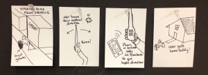
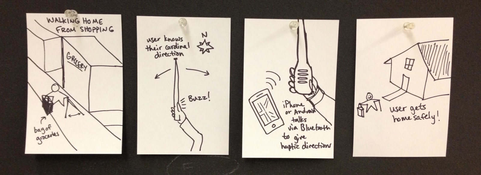
1) Walking home from a shopping trip: This task is moderately difficult with existing means, but will likely be much easier and safer with our proposed technology. We describe a scenario in which the user begins at a mall or grocery store and walks a potentially unfamiliar path which involves staying on sidewalks, crossing a few streets, and avoiding obstacles such as other pedestrians while staying on route to their destination by identifying particular landmarks. This must be accomplished all while carrying the purchased items and possibly manipulating a GPS device.
Currently, such a task involves utilizing a cane or similar tool to identify obstacles and landmarks. While basic cane travel is an art that has been developed over generations and has many invaluable merits, it also carries several drawbacks. Firstly, the cane must be carried around constantly and kept track of throughout the day, limiting the hands that the user has to carry other items (or interact with objects or people). If the user is utilizing a GPS device to guide them to their destination (as most blind people have now become accustomed to doing with their smartphones), they must use their other hand to manipulate the device. Thus, unless the user is setting something down or fumbling to carry everything, they will have to stop and set down things simply to operate their GPS. On the other hand, because the cane can only help guide the user relative to their mentally tracked position, if the user has no GPS device and loses track of their cardinal orientation, they have few means by which to reorient themselves without asking for help.
With our proposed system, the user will no longer need to worry about tracking their cardinal orientation, because the system can immediately point them in the right direction through intuitive haptic feedback. Because the cane itself will integrate with GPS technology via bluetooth, the user will not have to manipulate their phone in order to query directions or be guided along their route. This frees up a hand for the user to carry their items as needed.

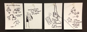
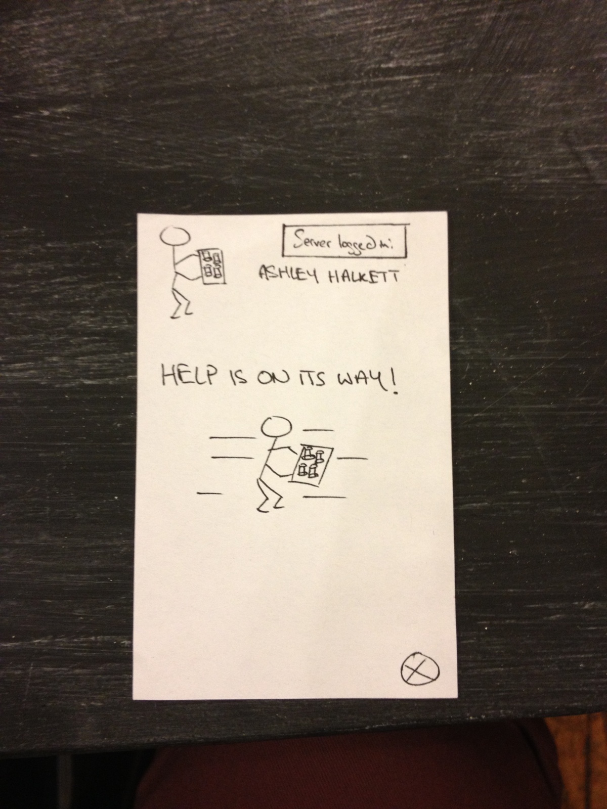
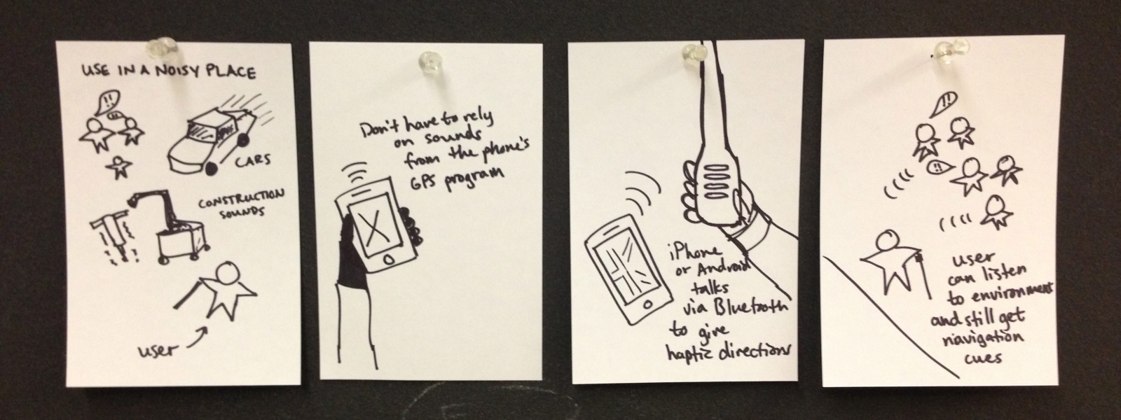
2) Following a route in a noisy area: This is another fairly difficult task which will become significantly easier using our system. An example of this task is getting from one place to another in city region such as Manhattan. Because the user must receive their navigation directions via audible commands, the user has trouble navigating if they cannot hear their commands. Currently, aside from straining to hear, the main option for a blind person to still manage is by using headphones. However, most blind users prefer not to use headphones, as doing so diminishes their ability to hear environmental cues, on which they heavily rely to navigate.
Our system solves this problem by relaying directional commands in a tactile manner, allowing the person to clearly receive guidance even in the noisiest of environments. Similarly, the need for headphones is eliminated, allowing a person to never disrupt their perception of environmental cues by the occurrence of a GPS message. Guidance is continuous and silent, allowing the user to constantly know where they headed and how to get there.

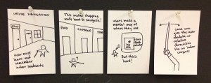
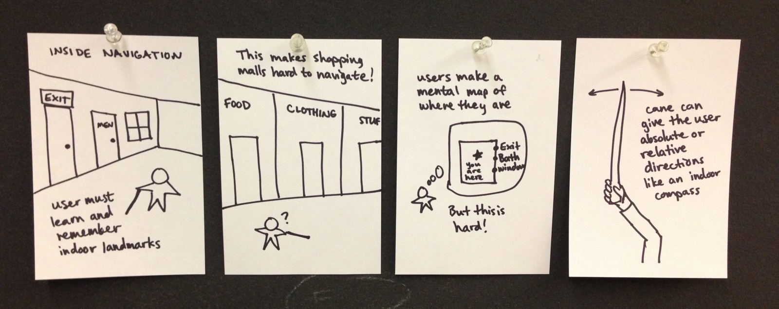
3) Navigating an unfamiliar indoor space. Despite the preconceptions we might have about the outdoors being hazardous, this task is actually the most difficult of all. Currently, because most GPS technologies do not function well indoors, unfamiliar indoor spaces are generally agreed to be the most intimidating and difficult to navigate.
With current means, blind people typically must ask for help in locating features of an indoor space (the door leading somewhere, the water fountain, etc.), and build a mental map of where everything is relative to themselves and the entrance of the building. The cane can be used to tap alongside walls (“shorelining”) or to identify basic object features (i.e. locate the doorknob). Unfortunately, if the person loses their orientation even momentarily, their previous sense of location is entirely lost, and help must again be sought. For this reason, any indoor space from a bathroom to a ballroom poses the threat of getting “lost.”
Our system uses a built-in compass to constantly keep the user cardinally oriented, or oriented in the direction of a destination if they so choose. As a result, a user can build their mental schema relative to absolute directions and never worry about losing sight of, e.g., where North is located. The user need not draw attention to himself through audible means or carry a separate device for indoors such as a compass (or manipulate their smartphone with their only free hand). Most importantly, the user’s autonomy is not limited because the directional functionality integrated into their cane gives them the ability to navigate these otherwise intimidating spaces on their own.
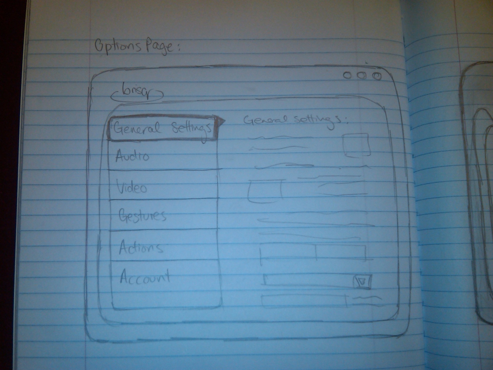
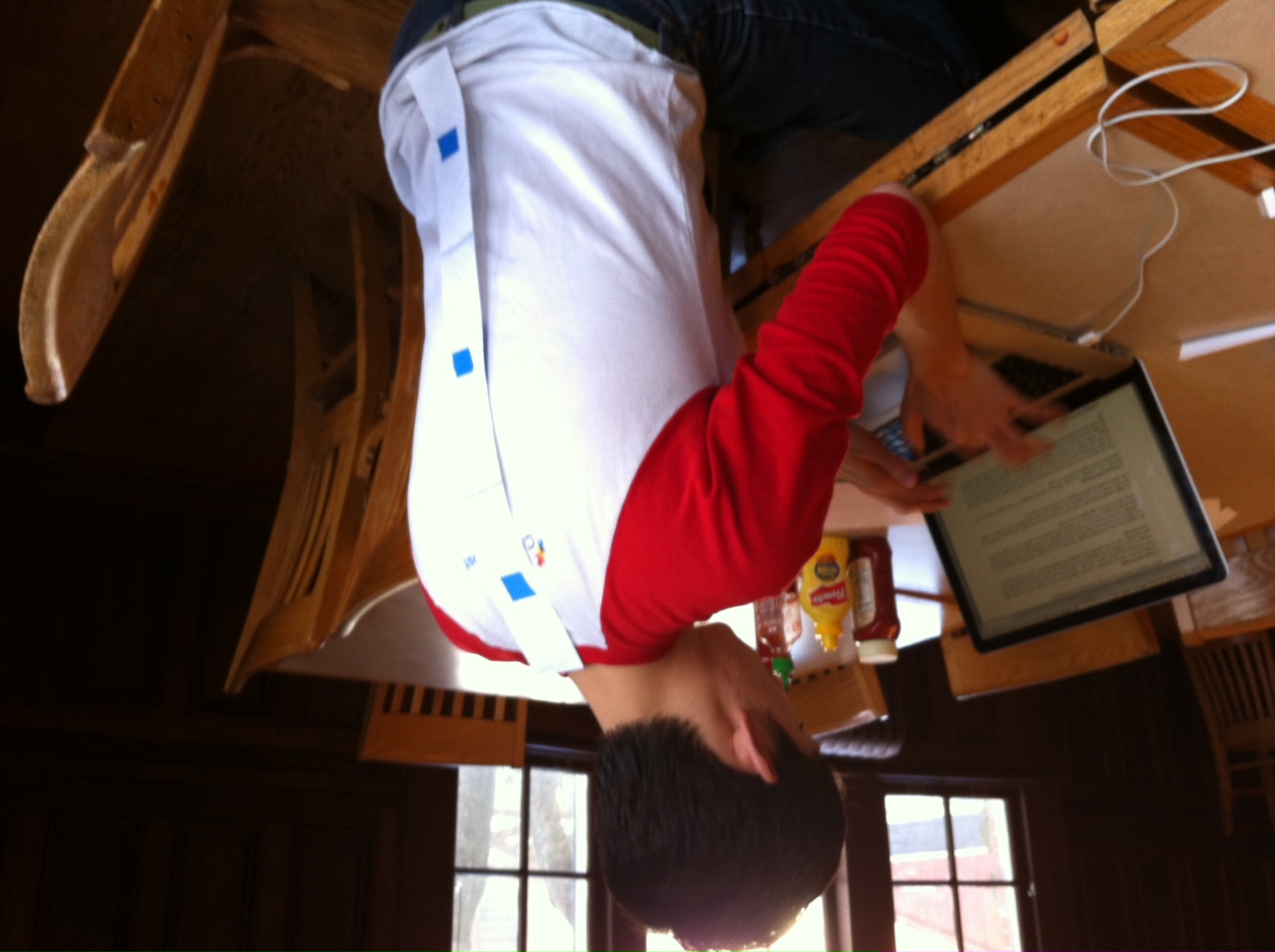
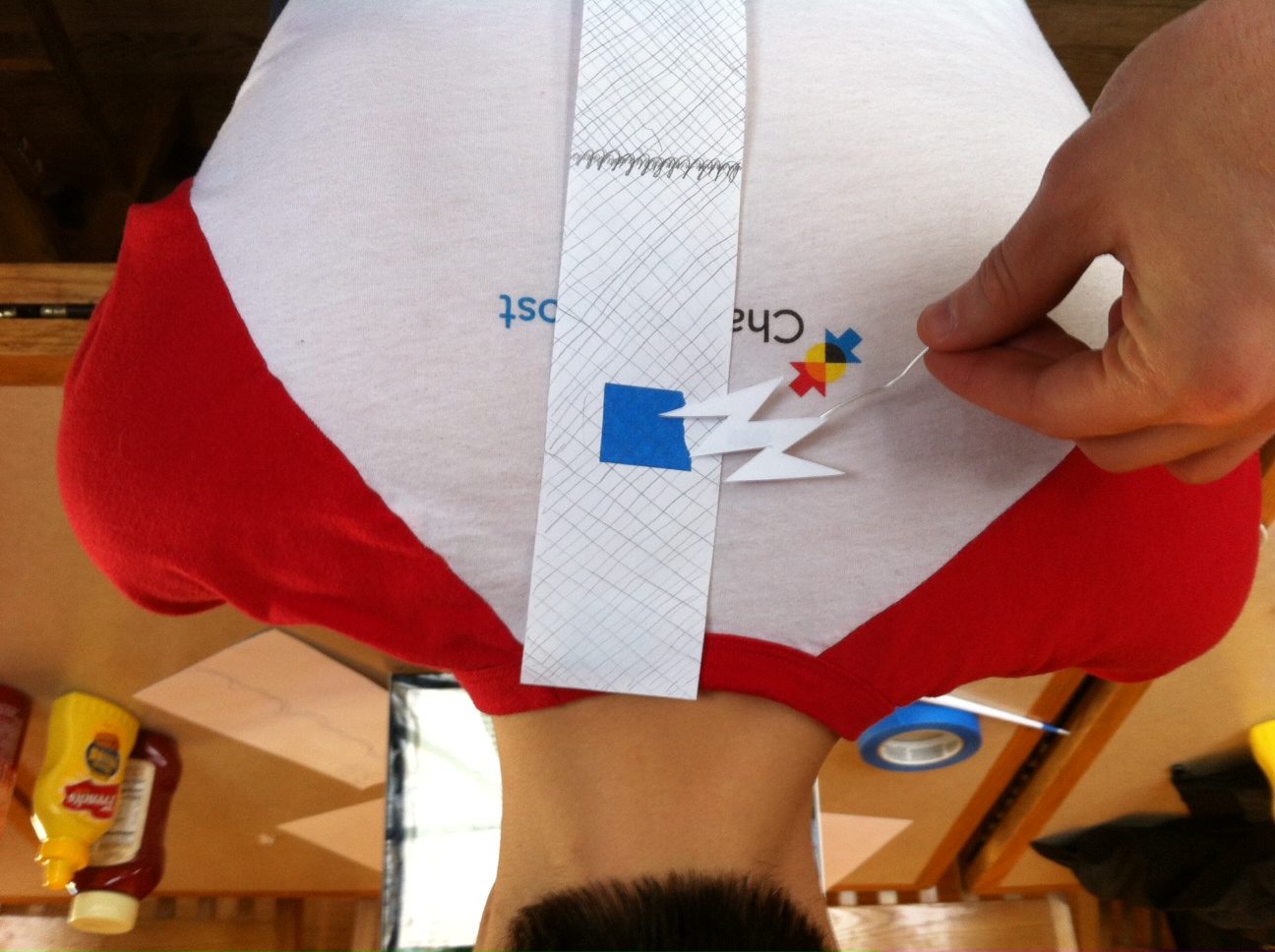
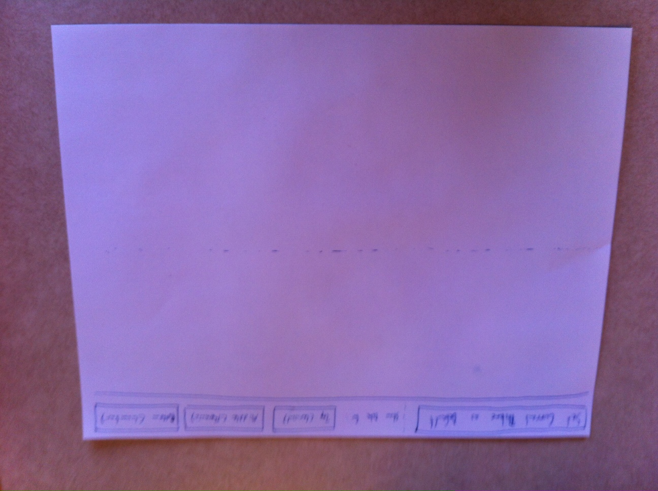
Interface Design

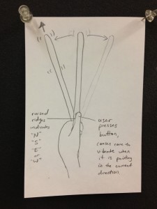
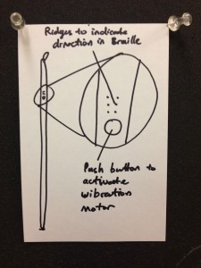
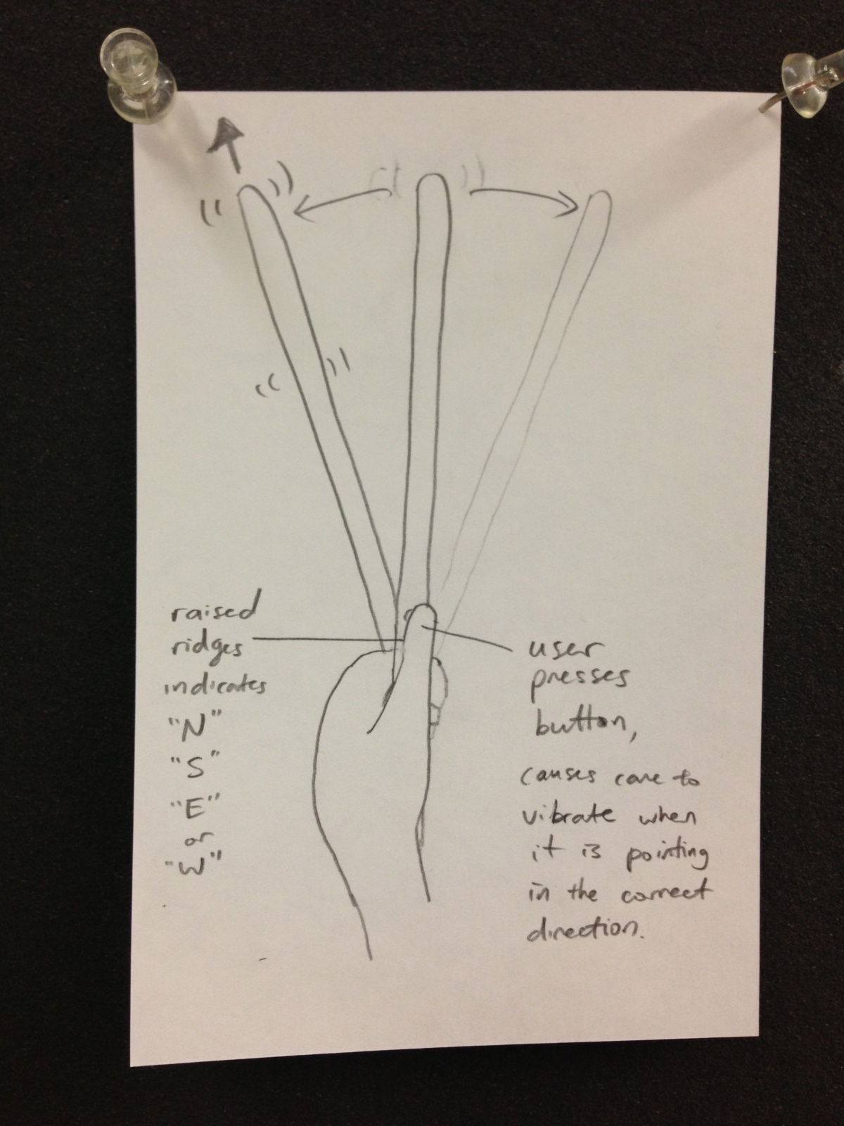
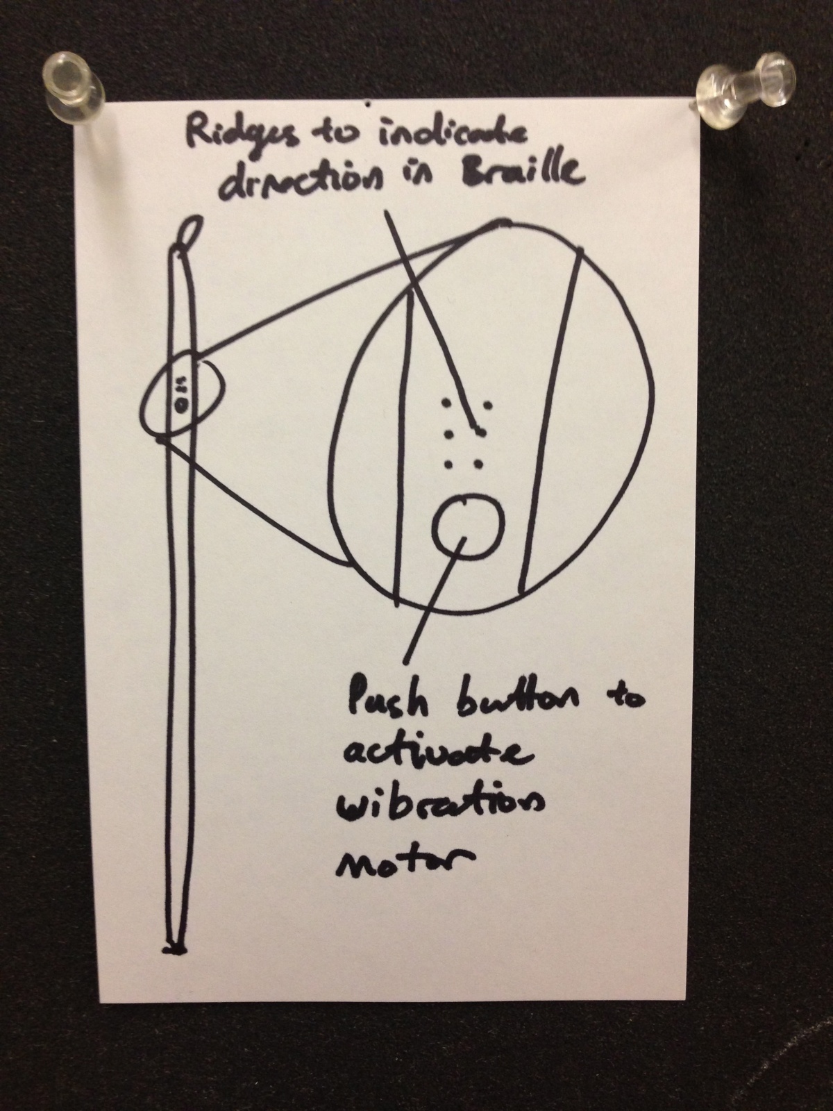
Description: It was apparent from our interviews that our device should not impede users’ ability to receive tactile and auditory feedback from their environment. By augmenting the cane with haptic feedback and directional intelligence, we hope to create a dramatically improved interface for navigation while preserving those aspects that have become customary for the blind. Specifically, the “Bluecane” will be able to intelligently identify cardinal directions and orient the user through vibration feedback. Bluetooth connectivity will enable the cane to communicate with the user’s existing Android or iOS device and receive information about the user’s destination.  A series of multipurpose braille-like ridges could communicate any contextually-relevant information, including simple navigational directions and other path-finding help. The greatest advantage of an improved cane is that it wouldn’t disrupt or distract the user, unlike an audible navigation system, and it gives the user a free hand while walking.

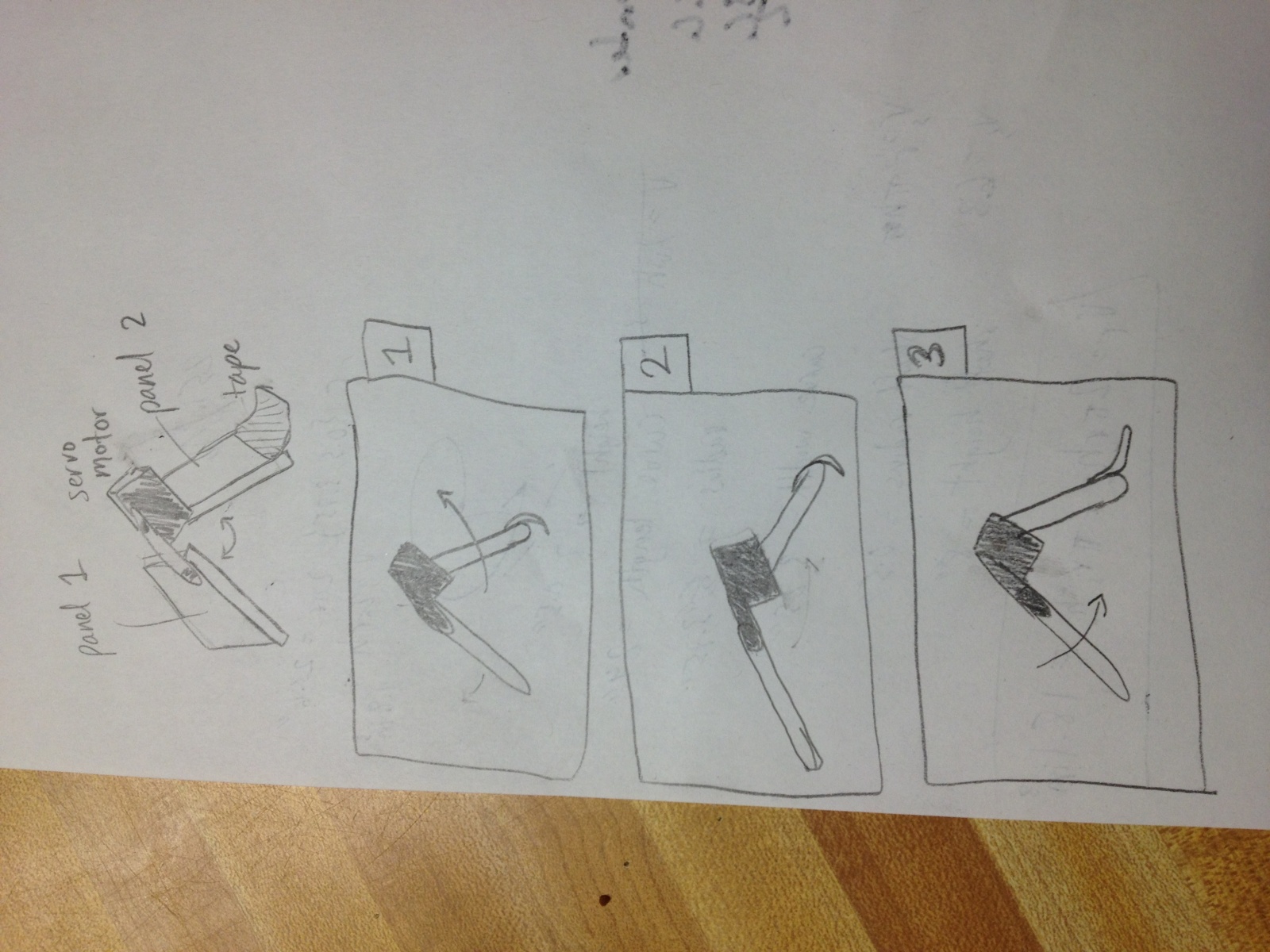
Storyboard for Task 1

Storyboard for Task 2

Storyboard for Task 3
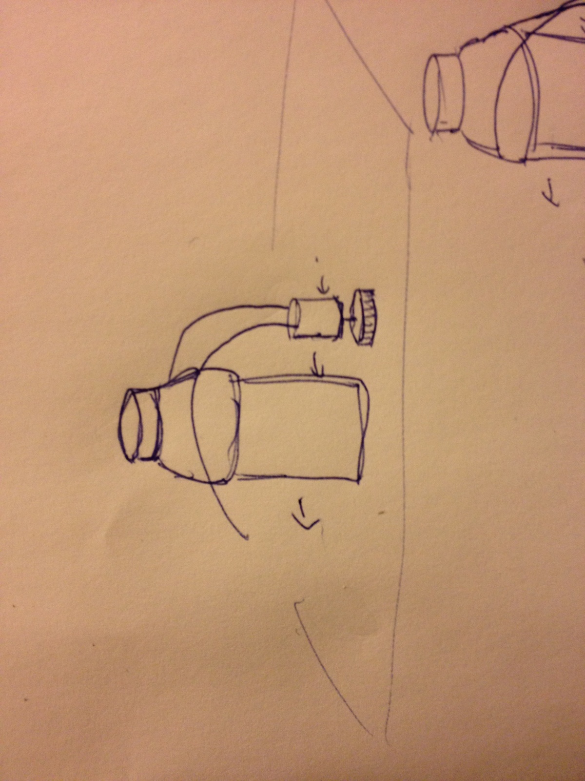
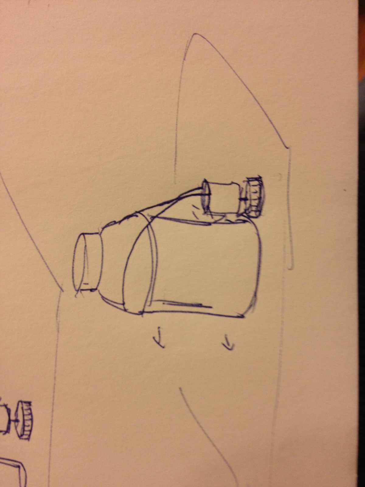
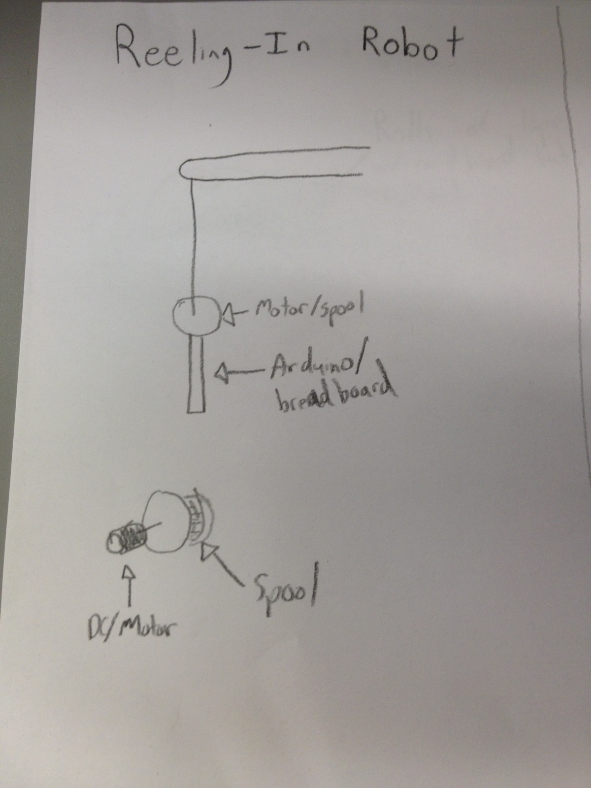
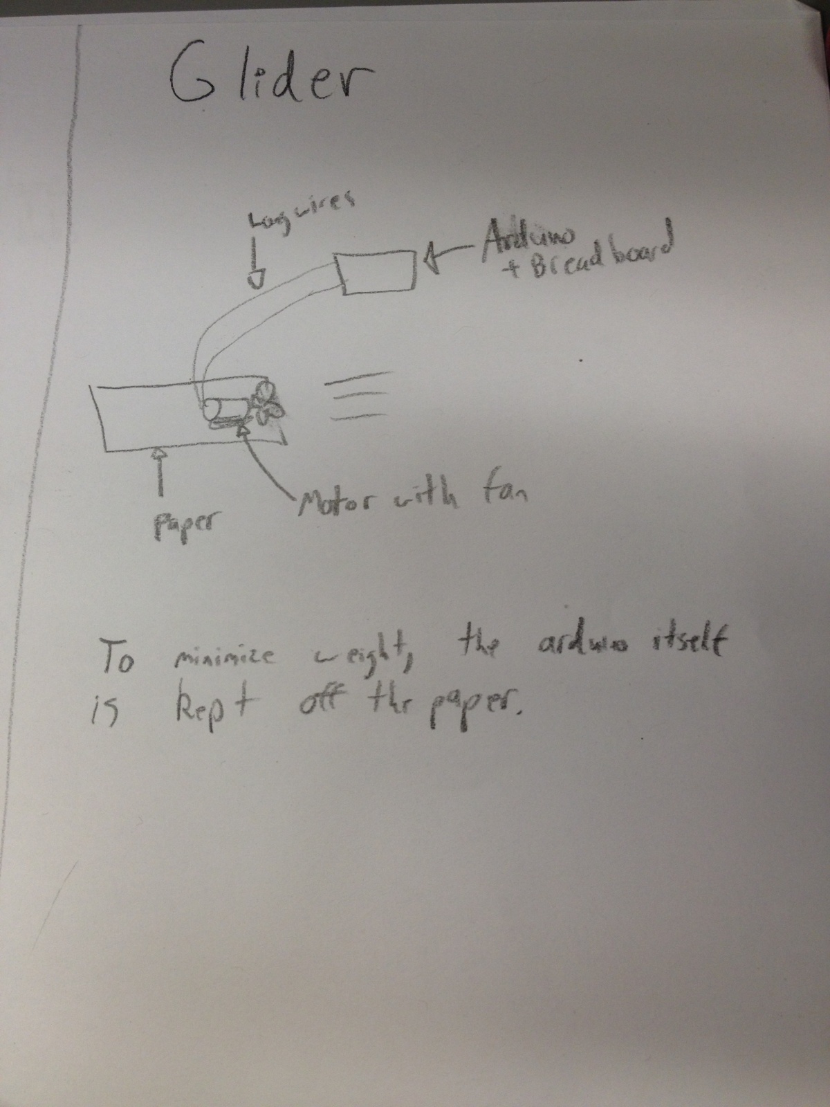
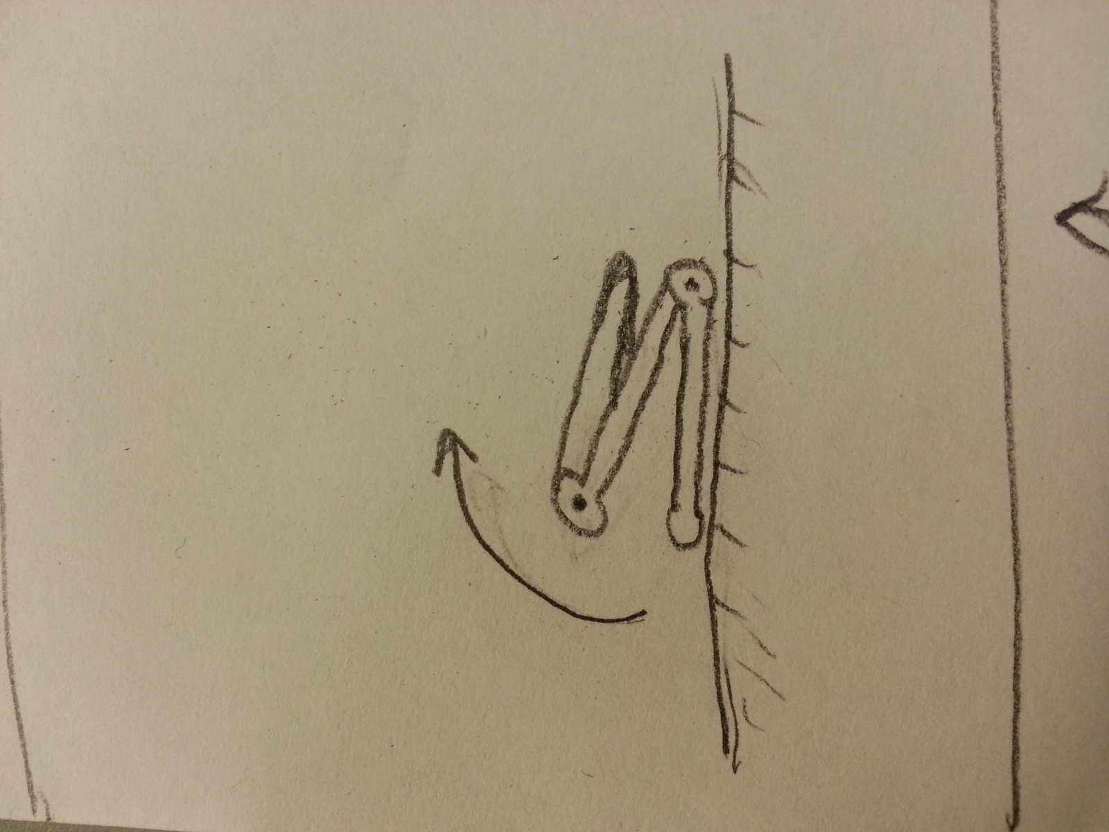
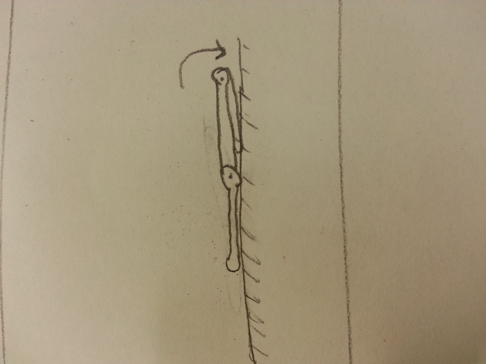
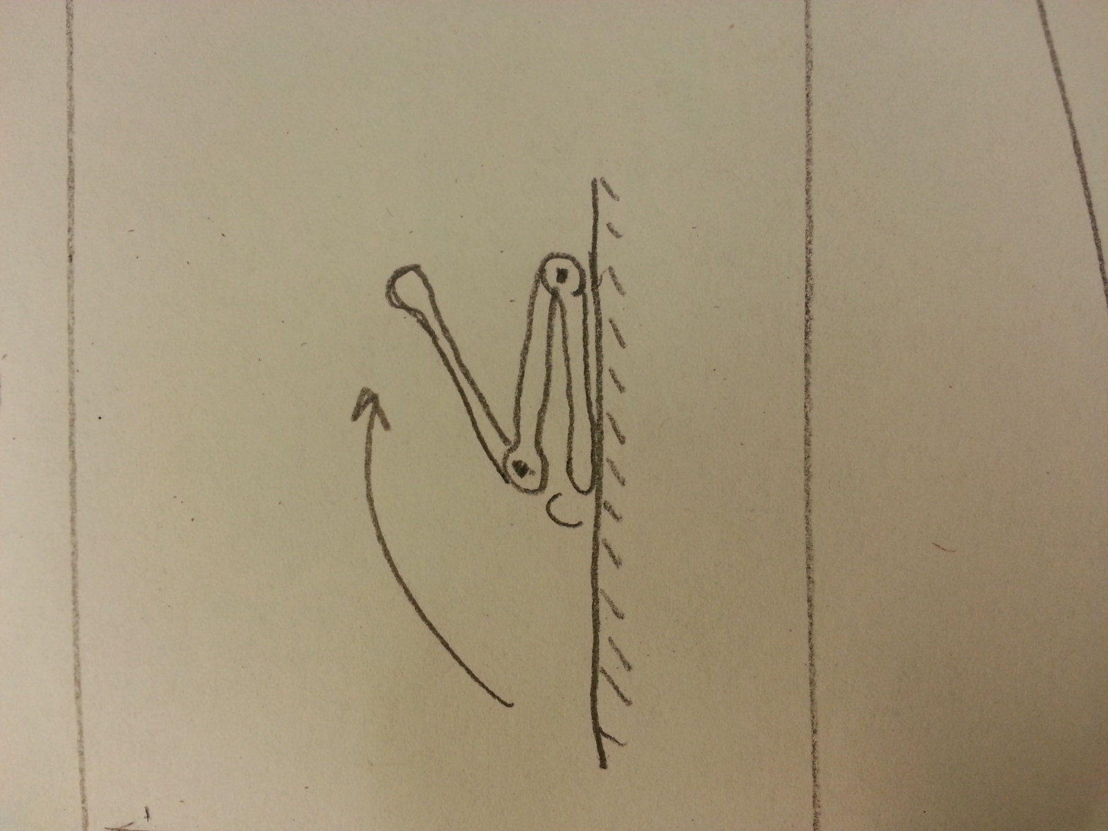
Design sketch

Design sketch


Lab 3: Motor Control

Lab 3: Motor Control

Bereket Abraham
Lauren Berdick
Ryan Soussan
Andrew Ferg

Group #24: The Cereal Killers

Z Flipper

We built the Z-Flipper, a robot designed to flip over itself multiple times. It was made out of 3 panels connected by servo motors at the joints. The construction was good, but our servo motors were too weak to lift the entire weight of the robot. The second robot we constructed, the Wormotrom, moved like an inchworm. The robot moved at a slow but steady pace, and put less strain on the motors. However, we were unable to control the direction the robot moved in. In the future, we would remember to consider the strength of our motors during the brainstorming and idea selection process.

12 Robot Ideas

1. 2 servos on either side of a piece of styrofoam and have it crawl along.

2. 2 DC motors attached to wheels on either side of a piece of styrofoam with a passive trailing wheel. A 3 wheel cart. You could turn by spinning one side faster than the other.

3. Put a piece of styrofoam on a 3-wheeled tripod. Attach a DC motor on the back as a fan. Blows across the table.

4. 2 servos attached to a ribbon. The servos turn in opposite directions, causing the ribbon to contract and expand. Much like a worm.

5. One servo with a gripper claw attached. The motor sweeps from 0 to 30 deg slows, and then back quickly. The robot claws it way across the table. Perhaps you would need two trailing legs for stability.

6. The same thing as above except now we have 2 gripper claws on either side. This configuration could also be used to climb as well as crawl.

7. Attach tiny helicopter blades to the DC motor. The robot flies into the air with a burst of speed, then glides over to the other side of the table.

8. Two DC motors attached to wheels and connected by some kind of thick rubber band or track. The motors are fixed together and the track rotates around them, like a really basic tank.

9. Create a hollow cylinder with a DC motor at the central axis. Attached to the motor is a weighted rod, or a pendulum. As the motor turns, it shifts the cylinder’s center of mass, causing it to turn.

10. A four legged robot with a rotating hip. One servo would control the hip and one DC motor would control the front two legs. The back legs would be passive / wheeled. The front legs would be 180 degrees out of phase, so that as the hip turned one leg would be in the air and the other would be pulling the robot forward.

11. The entire path has a track or ladder. The robot simply has a DC motor that pulls itself along the track.

12. Cover the table in a few inches of water. Make a small boat and with 2 paddles connected to servo motors. Or a DC motor connected to a propellor.

13. 3 flat plates in the shape of a “Z”. At each joint is a servo motor. The plates open up, causing the robot to flip over. The robot moves forward by flip over and over in the right direction.

Final Idea: #13

At first, we thought about doing the crawler, #6.

crawler

But then we decided on the “Z Flipper”, #13.

zflipper

Here is a diagram on how the Z Flipper would move.

gait

pic1

pic2

pic3

pic4

Parts List

3 Cardboard plates made from gum packaging.
2 stepper motors
1 arduino microcontroller
2 long, stiff wires for attaching the motors
tape
jumper wires

Instructions

First construct the flipper. Attach the motors to the plates using tape and wires. At a joint, the motor body connects to one of the plates using tape. The motor arms connect to the other plate. This connection is much weaker and needs the wire to reinforce it. When that’s done, use the jumper cables to connect the motors to the arduino. Finally, upload the code and let it go. The code is designed to turn the motor, wait a set amount of time, and then turn the other motor. And so on.

Testing


Video of the Z-Flipper. We were able to construct the flipper mechanism, but the motors were too weak to move unaided.

In order to salvage a workable robot, we stripped off the second joint, leaving only 2 panels connected by a servo motor. Now the robot was basically a hinge that could open and close. Instead of flipping over itself, the robot would now move using an inch-worm type motion. To create forward motion, I covered the back panel in smooth electrical tape and put a flap of scotch tape on the front panel. When bending open, the flap would curl under itself and slide forward. When bending close, the sticky side would catch on the table and pull the rest of the robot forward. I call it the Wormotron. Check out our new diagrams and video.

wormotron_diagram
Diagram


Wormotron in action.

Arduino Code

/*
Lab 3, COS 436
Z Flipper Robot
Group 24: The Cereal Killers
*/

#include  

int jointPinA = 9;
Servo servoA;
int angleA = 0;
int steps = 10;
int on = 1;
 
void setup() {
  servoA.attach(jointPinA);
  
  Serial.begin(9600);
  Serial.println("Ready");
}
 
 
void loop() 
{   
  if(on == 1) {
    for(int i = 0; i < steps; i++) 
    {
      openJointA();
      delay(15);
      closeJointA();
      delay(15);
    }
    on = 0;    
    servoA.detach();
  }
}

void openJointA() {
  // scan from current position to 180 degrees
  for(; angleA  0; angleA--)  
  {
    servoA.write(angleA);
    delay(15);
  }
}