Kratos
Starting in February of 2008, our team of 9 student developers had only 4 months to design, build, program and test a ground robot for the 2008 Intelligent Ground Vehicle Competition. Drawing from experiences gained from competing in the DARPA Urban Challenge, the team built Kratos.
Hardware Design and Construction
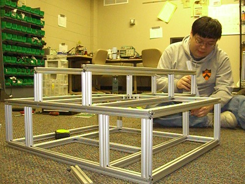
Kratos was designed and built entirely from scratch. The short development cycle required us to make careful and well informed design decisions, so as to minimize failures of the robot’s hardware.
To start with, the entire robot was designed using Autodesk Inventor CAD software. By accurately modeling components within the CAD software, we were able to obtain exact placement of all the components and exact dimensions for the chassis before construction began.
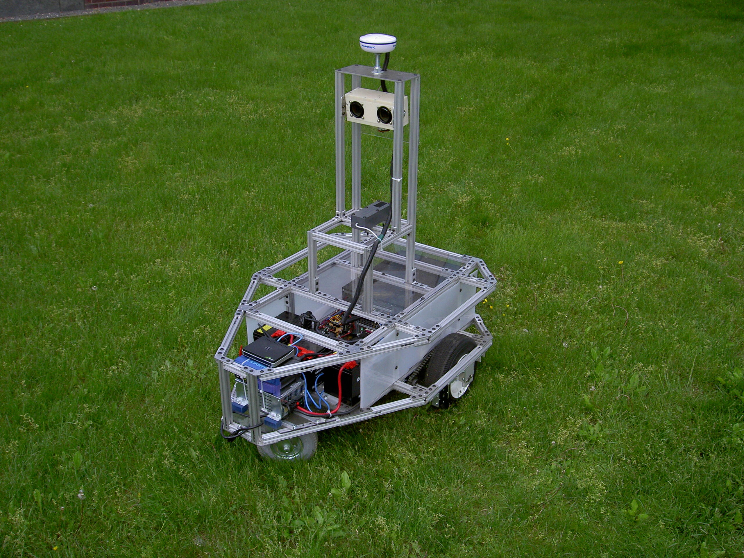
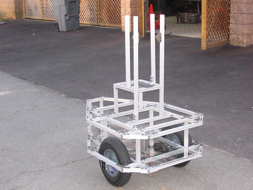
The chassis was primarily constructed using the 80/20 extruded aluminum framing system. Each joint was held together using bolts and custom-machined aluminum plates. The initial design and construction of the chassis took about a month between conception to the first full assembly shown in the photo to the left.
For Kratos’ drivetrain, we opted for an arrangement with two CIM motors per side. They are connected to the wheels with a BaneBots 12:1 planetary gearbox reduction and a 10:3 chain drive reduction. The wheels are 12.4″ diameter pneumatic wheels with sawtooth treads. each motor is connected to an Innovation First Victor 884 motor controller.
For Kratos’ drivetrain, we opted for an arrangement with two CIM motors per side. They are connected to the wheels with a BaneBots 12:1 planetary gearbox reduction and a 10:3 chain drive reduction. The wheels are 12.4″ diameter pneumatic wheels with sawtooth treads. each motor is connected to an Innovation First Victor 884 motor controller.
Sensors and Electronics
Kratos had three sensors for pose (position and orientation) measurement a Hemisphere GPS unit provides latitude and longitude measurements accurate up to 10 cm. A Honeywell digital compass provided measurements of heading. Optical encoders were mounted on each wheel axle to measure differential wheel speeds for dead reckoning. A single Point Grey Research Bumblebee2 color stereo camera served as Kratos’ only environmental sensor, allowing the robot to “see” obstacles in its path and lanes painted on the ground. All digital I/O were handled by a LabJack UE9 data acquisition unit, which took inputs from the encoders and outputs PWM signals to the motor controllers. The robot’s remote E-stop was handled by a R/C radio receiver attached to an Innovation First controller unit operated on a separate power supply from the rest of the robot.
Power Systems and Computing
The three 12VDC deep-cycle batteries onboard Kratos provided enough power for up to one hour of full operation and over 5 hours on standby. A battery charger was also mounted onboard, allowing the robot to charge by simply plugging in to a standard socket. Two custom-built Intel Core2Duo-powered computers handled the navigation algorithms and stereo vision computations, respectively. As with all other PAVE robotics projects, Kratos’ computers were connected to a pair of wireless routers configured to allow access to the internet and to allow developers to connect remotely.
Software
Both computers on Kratos ran Windows Server 2003. All software development was done in Microsoft Visual Studio. This combination allowed us to work with a set-up we were familiar with from our participation in the 2007 DARPA Urban Challenge. However, we did use a different software framework, the Interprocess Communication Framework (IPC). We developed a C++ wrapper for IPC, dubbed “IPC++”.