
Group members: Alan Thorne, Dylan Bowman, Harvest Zhang, Tae Jun Ham
Sketches:
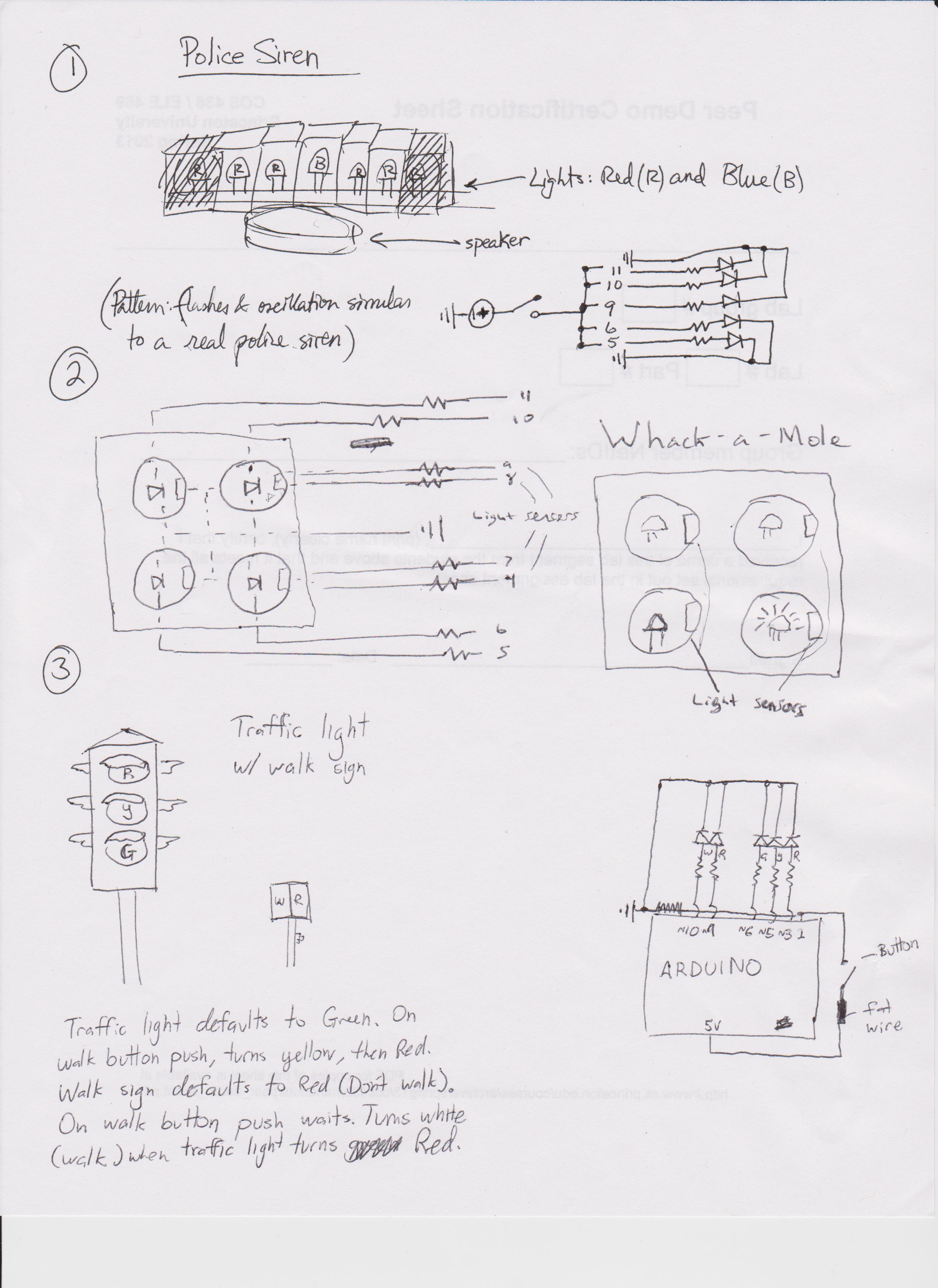
Three sketches. The first, (and the one we built,) a police siren complete with flashing lights and wailing speaker, with no input other than a button (used like a switch) to turn it on or off. The second idea was a whack-a-LED game, where we use light sensors along with LEDs poking out of a grid; to play, you cover up the grid hole where the LED is lit, and the light sensor placed there detects that and gives you points. The final idea is a traffic light that responds to a walk signal, but is otherwise a normal traffic light that is programmed to hold the same durations for red and green every cycle.
The Blues and Tunes Police Siren:
The Blues and Tunes police siren has an LED light bar, a single auxiliary LED flasher, and a speaker in order to flag down speeding Arduinos. It executes two types of flashing and wailing — one in the style of American police vehicles and the other more European (the European siren mode was added primarily because we ran out of blue and red LEDs, and used two yellow ones, which do show up in some European police vehicles but almost never in US vehicles). It has a pushbutton that starts and stops the siren.
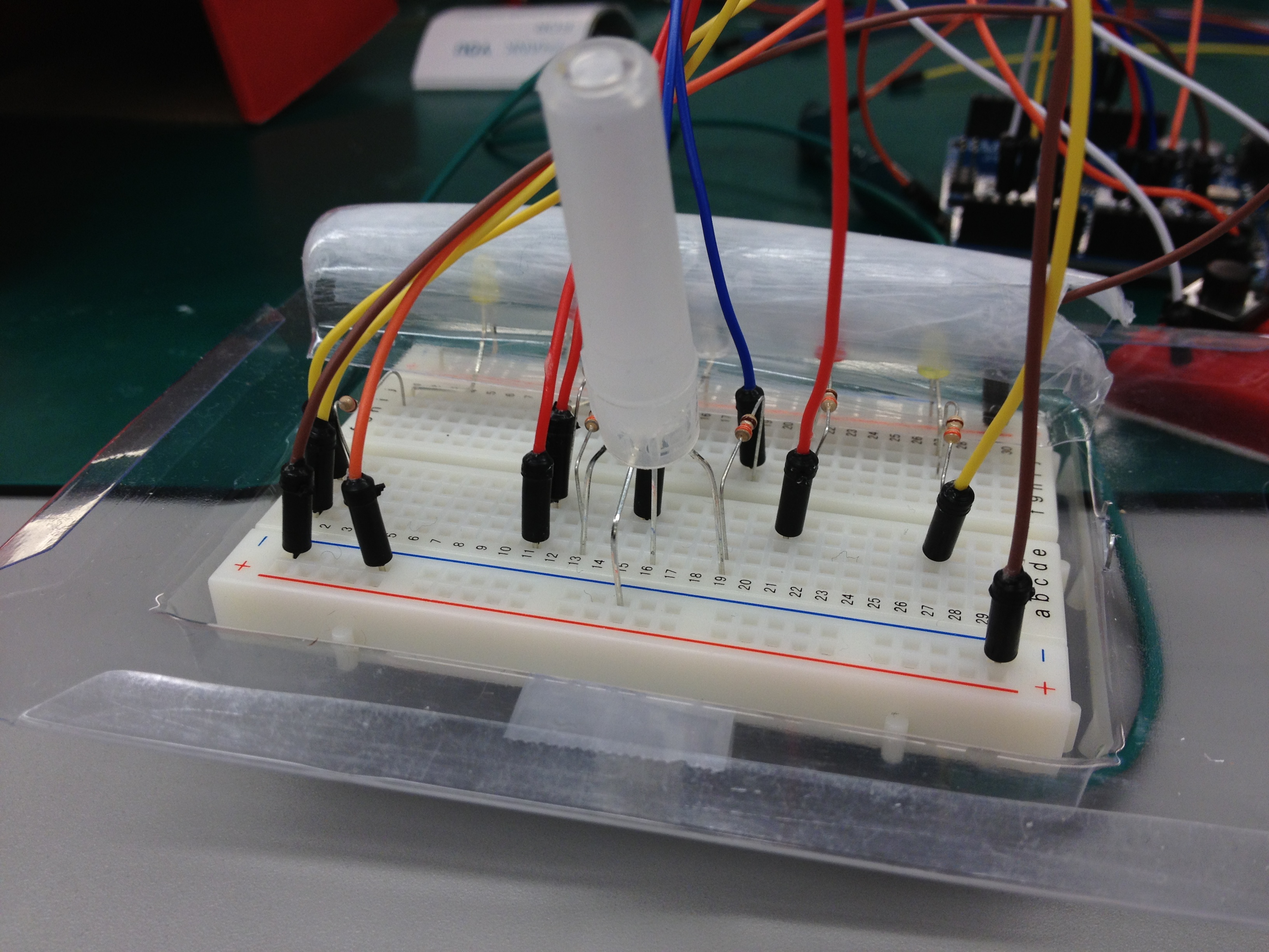
Visible here is the large breadboard, containing the main LED light bar as well as the auxiliary one, mounted on the plastic blister packaging that also serves as a crude sort of resonator for the piezo speaker underneath.

Visible here: the red breadboard containing the on/off button, the Arduino, and the main breadboard.

Here we see the lights in action. This particular implementation features two separate light and sound patterns.
For the most part, it works pretty well; the siren isn’t particularly loud, but it is annoying enough to earn looks from other lab groups if left on. The diffusers are acceptable but not very nice. A better light bar with a bunch of fresnel lenses would be ideal, but no one had miniature police light bar diffusers lying around. We could have also programmed the pushbutton to cycle through various types of sirens, but in this implementation we just hardcoded two alternating patterns.
It’s the Arduino Carabinieri! (video)
The components:
- (1) Large blue LED
- (2) Small red LED
- (2) Small yellow LED
- (1) RGB LED
- (6) 330 Ohm resistors
- (1) Pushbutton
- (1) Piezo speaker
- (1) Arduino
- (1) Large breadboard
- (1) Small breadboard
- (n) A bunch of jump wires
- (1) Translucent pen cap or similar diffuser
- (1) Blister packaging strip covered in scotch tape for the main light bar
Make one yourself:
- Arrange all but the RGB LED in a visually pleasing manner on the large breadboard in the style of a police light bar.
- Add one 330 Ohm resistor between each LED and the Arduino. Connect the yellow RGBs to the same I/O pin and the red RGBs to the same I/O pin. Give the blue one its own pin. These are all digital I/O pins.
- Place the RGB LED in a prominent location on the large breadboard. We will be using only the red and blue pins (not the green one) from the RGB LED. Connect those (through resistors) to two I/O pins.
- Mount the pushbutton on the small breadboard and wire it up to the 5V pin. (You could also put it on the large breadboard with everything else, but there’s a lot of stuff on that one already.)
- Wire up the piezo speaker to an I/O pin.
- Make an appropriately light-bar-styled diffuser out of something translucent, and make another one for the RGB LED. Put them over the LEDs.
- The piezo speaker also gets much louder if you give it something larger to vibrate, so tape the piezo onto a blister package or something similar to make it sound more like a siren and less like a singing holiday card.
- Write up the code, and play the siren!
The code:
// ENUMS
int OFF = 0;
int ON = 1;
int TRANSITION = 2;

// Names for things
int button = 2;
int y = 3;
int r = 5;
int b = 6;
int tri_r = 9;
int tri_b = 10;
int speaker = 11;
int state = ON;
int current_state = ON;

// the setup routine runs once when you press reset:
void setup() {
   pinMode(button, INPUT);
}

// the loop routine runs over and over again forever:
void loop() {
  button_mode();

  if (current_state == ON) {
    for (int j = 0; j < 4; j++) {
      for (int i = 0; i <= 255; i++) {
        digitalWrite(speaker, HIGH);
        delayMicroseconds(300 - i);
        digitalWrite(speaker, LOW);
        delayMicroseconds(300 - i);
        analogWrite(speaker, 255);

        analogWrite(y, i);
        analogWrite(r, 255-i);
        analogWrite(b, i);
        analogWrite(tri_r, i);
        analogWrite(tri_b, 255-i);
        button_mode();
        delay(1);
      }

      for (int i = 0; i <= 255; i++) {
        digitalWrite(speaker, HIGH);
        delayMicroseconds(i + 45);
        digitalWrite(speaker, LOW);
        delayMicroseconds(i + 45);
        analogWrite(speaker, 255);

        analogWrite(y, 255-i);
        analogWrite(r, i);
        analogWrite(b, 255-i);
        analogWrite(tri_r, 255-i);
        analogWrite(tri_b, i);
        button_mode();
        delay(1);
      }
    }

    for (int j = 0; j < 4; j++) {
      button_mode();

      for (int i = 0; i <= 200; i++) {
        digitalWrite(speaker, HIGH);
        delayMicroseconds(100);
        digitalWrite(speaker, LOW);
        delayMicroseconds(100);
        analogWrite(speaker, 255);
        button_mode();
        delay(1);
      }

      analogWrite(y, 0);
      analogWrite(r, 255);
      analogWrite(b, 0);
      analogWrite(tri_r, 255);
      analogWrite(tri_b, 0);

      for (int i = 0; i <= 1802; i++) {
        digitalWrite(speaker, HIGH);
        delayMicroseconds(300);
        digitalWrite(speaker, LOW);
        delayMicroseconds(300);
        analogWrite(speaker, 255);
        button_mode();
        delay(1);
      }

      analogWrite(y, 255);
      analogWrite(r, 0);
      analogWrite(b, 255);
      analogWrite(tri_r, 0);
      analogWrite(tri_b, 255);
    }

  }
  else {
    analogWrite(tri_b, 0);
    analogWrite(tri_r, 0);
    analogWrite(y, 0);
    analogWrite(r, 0);
    analogWrite(b, 0);
  }
}

void button_mode() {
  if (digitalRead(button) == HIGH) {
    state = TRANSITION;
  } else {
    if (state == TRANSITION) {
      if (current_state == OFF) {
        current_state = ON;
      } else if (current_state == ON) {
        current_state = OFF;
      }
      state = OFF;
    }
  }
}
Now all you need to do is add wheels and a motor and some more sensors and and a body and you’ll have an Arduino-based police car!