
by Farhan Abrol (fabrol), Kuni Nagakura (nagakura@), Yaared-Al-Mehairi (kyal@) and Joe Turchiano (jturchia)
Concept:
For our diffuser, we designed an authentic tri-color Bedside Floral Lamp. The lamp was constructed from tree branch (spine of lamp), CD casing (base of lamp), six single-colored LED lights (red, green, and yellow), several wires, 6 short-size rolling papers, strips of aluminum foil, and a hot glue gun. Three potentiometers control the LED lights on the lamp (one for red, one for green, and one for yellow). When users wish to turn the lamp on, they simply twist the potentiometers to increase the brightness of the potentiometer’s corresponding color. With the LED lights on, the rolling papers, i.e. ‘light shades’, act as effective diffusers, which combined with the reflective strips of aluminum foil create visually attractive light patterns. Users can modify the lamps color and brightness with the potentiometers to set the appropriate mood. When users wish to turn the lamp off, they simply must reset the potentiometers, which turns all the lights off.
We decided to build a tri-color Bedside Floral Lamp because we wanted to create an aesthetically pleasing light source that users could tune to their mood. Conceptually, the LED lights represent the seeds of the flower and the aluminum strips the petals. Collectively, we are pleased with the result of our design. We especially like the addition of aluminum strips, which enhances the light diffusion process and therefore creates even more optically enjoyable effects.
One problem with our design though is that the aluminum strips are not rigid enough, and so tend to keep falling down, thereby failing to reflect the LED lights. An improvement that could be made would be to add some kind of support to the aluminum strips to keep them in place, and therefore acting as effective reflectors.
At first, we tried to build a Bedside CD Lamp because we thought CDs would be effective diffractors of light. It turned out that due to the limited power of our LED lights, CDs would only create a rather underwhelming light diffusion effect.
Design:
Through our design process, we considered 3 prototypes. Of these sketches, we actually conceived 2 of our prototypes and ultimately decided on our final design.
We began with the idea of the lamp and considered various ways to diffuse the light. Our first two prototypes used CDs to diffuse the light and our final prototype makes use of rolling papers and aluminum foil.
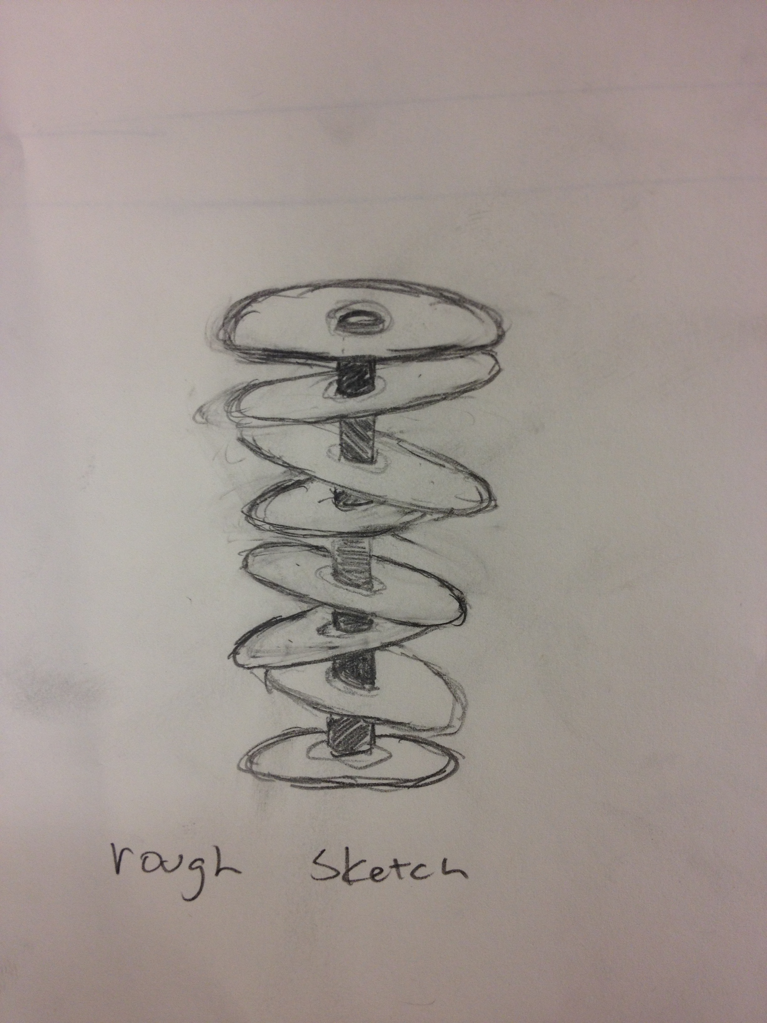
Initial rough sketch for our first prototype
This initial model was discarded because of structural issues. The 8 CDs would not stay together without adding additional structural supports. Our second prototype, which incorporates 3 CDs instead of 8 simplifies the structure of our lamp.
-

- Sketch of our second prototype
-
- Sketch of our circuitry
-
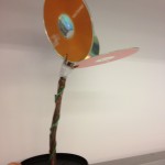
- Straight view of second prototype
-

- Aerial view of second prototype
We finished building our second prototype; however upon testing in various lighting conditions, we decided that the CDs were not adequate diffusers for our LED lights. Thus, for our final prototype, we chose to use different materials for our diffuser, and our final design incorporates rolling papers that wrap around the LED light and aluminum strips that surround the lights. A potentiometer that corresponds to the 3 sets of LED lights (red, green, yellow) give the user control over the mood and color of the lamp.
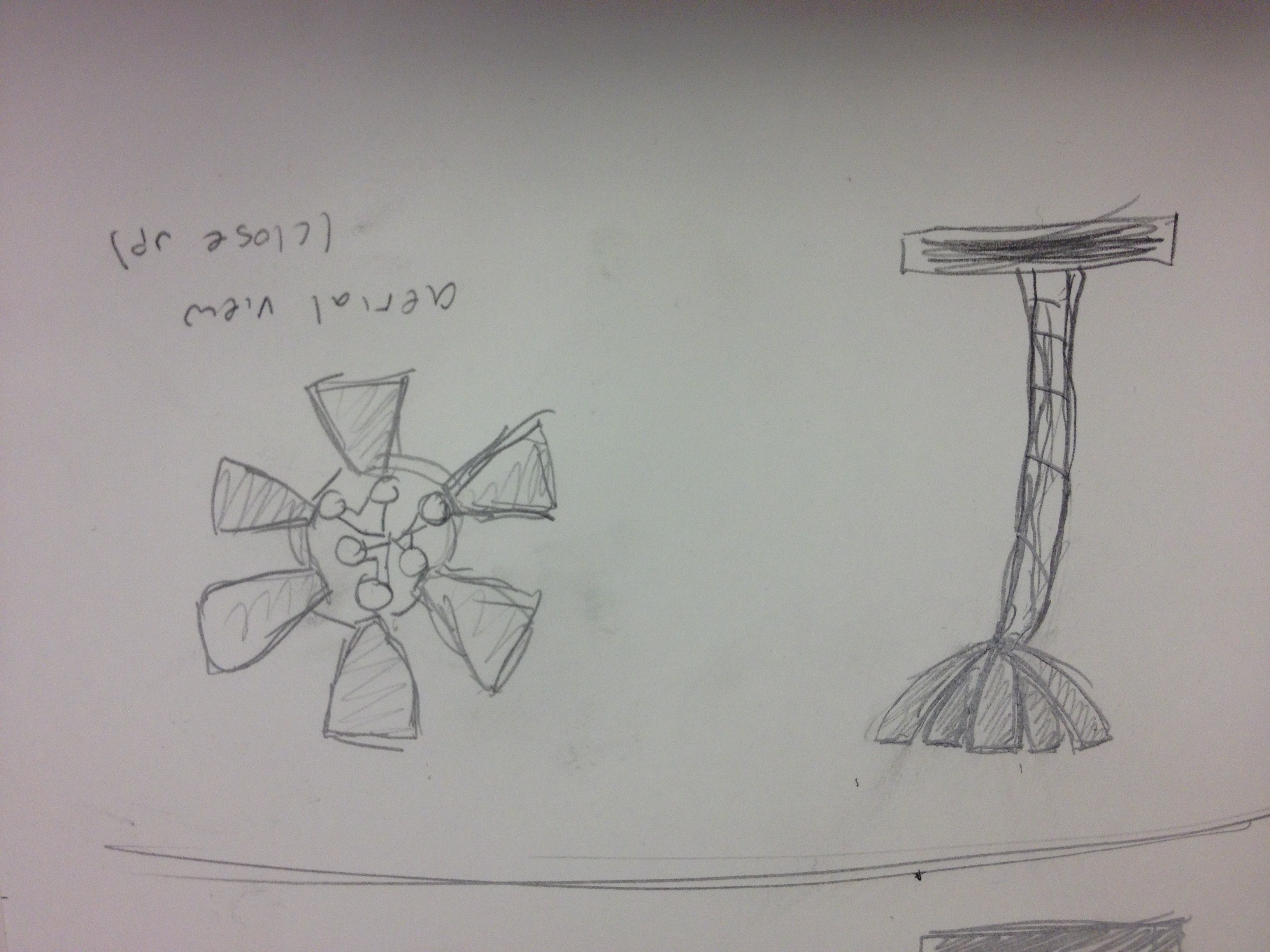
Sketch of prototype 3
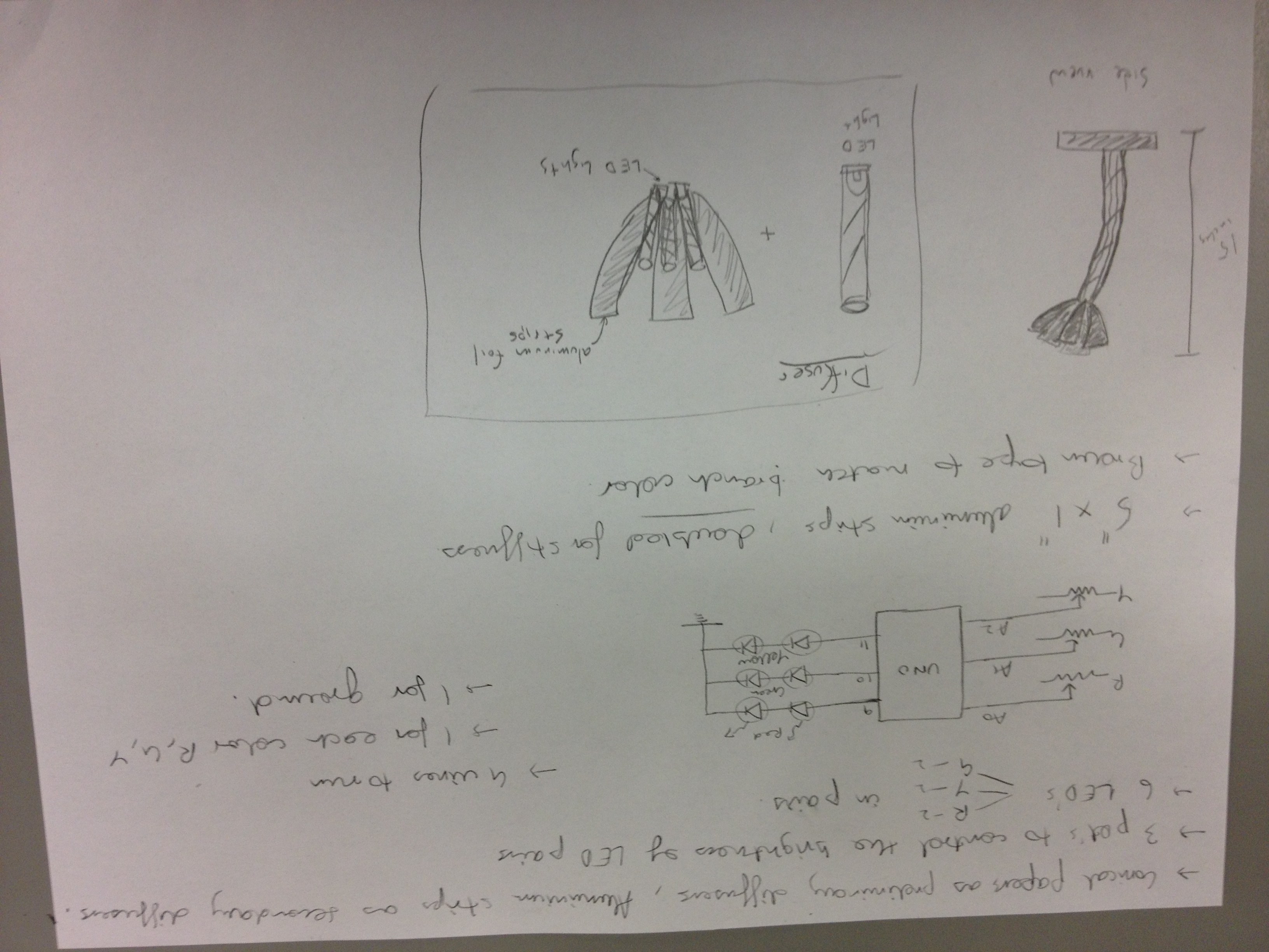
Final design sketch
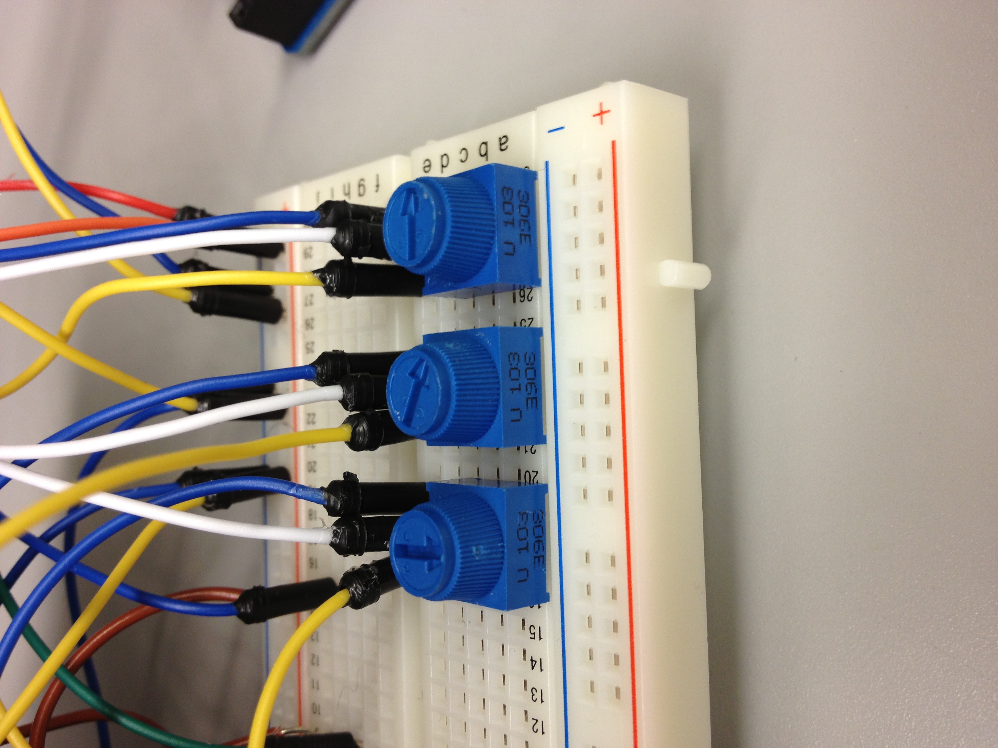
3 Potentiometer for each color (red, green, yellow)

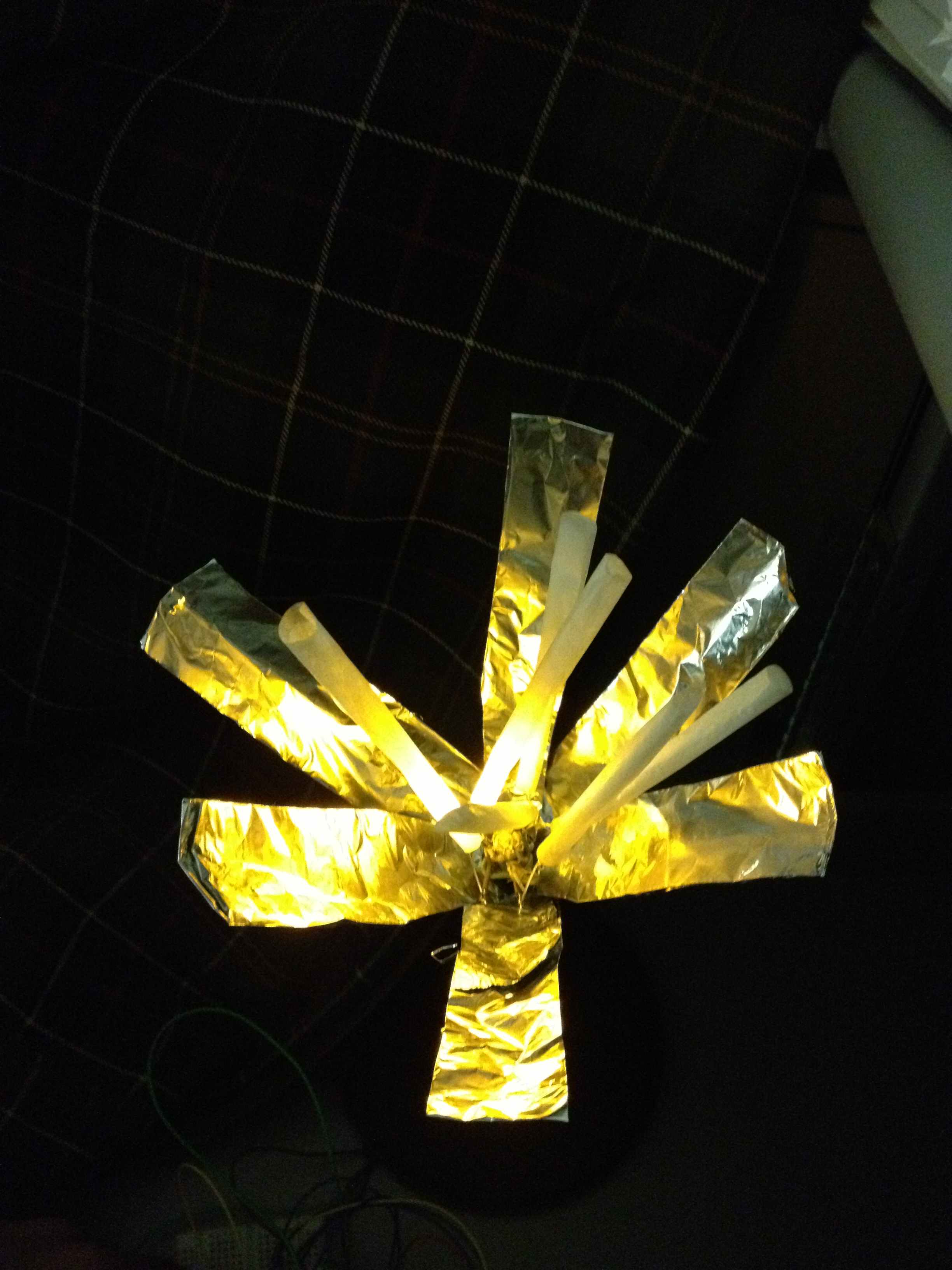
The Finished Prototype
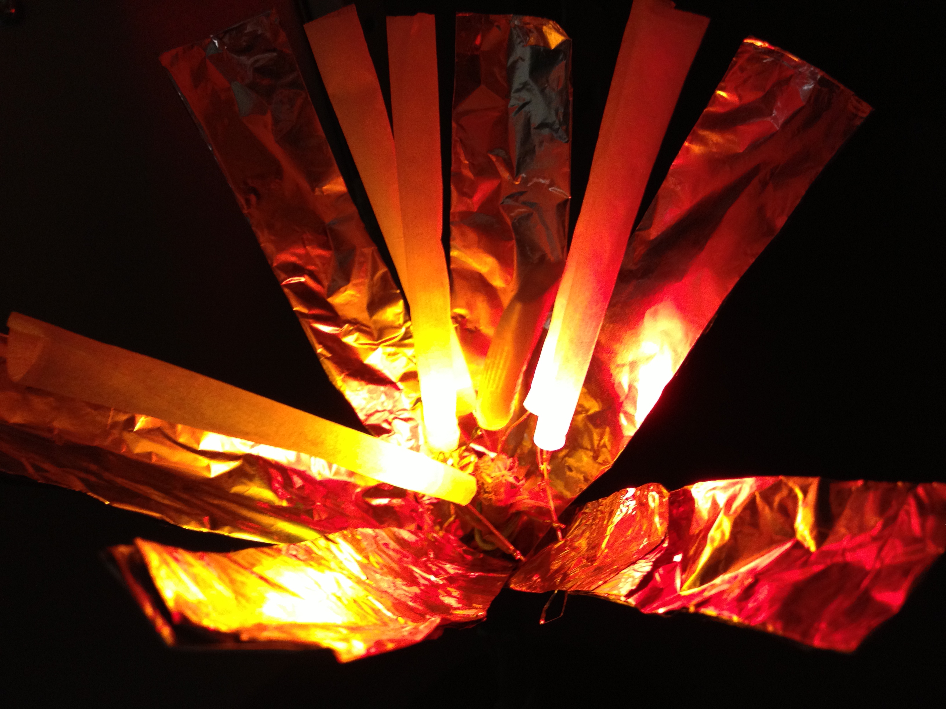
Close-up of the diffuser
Yellow LED’s
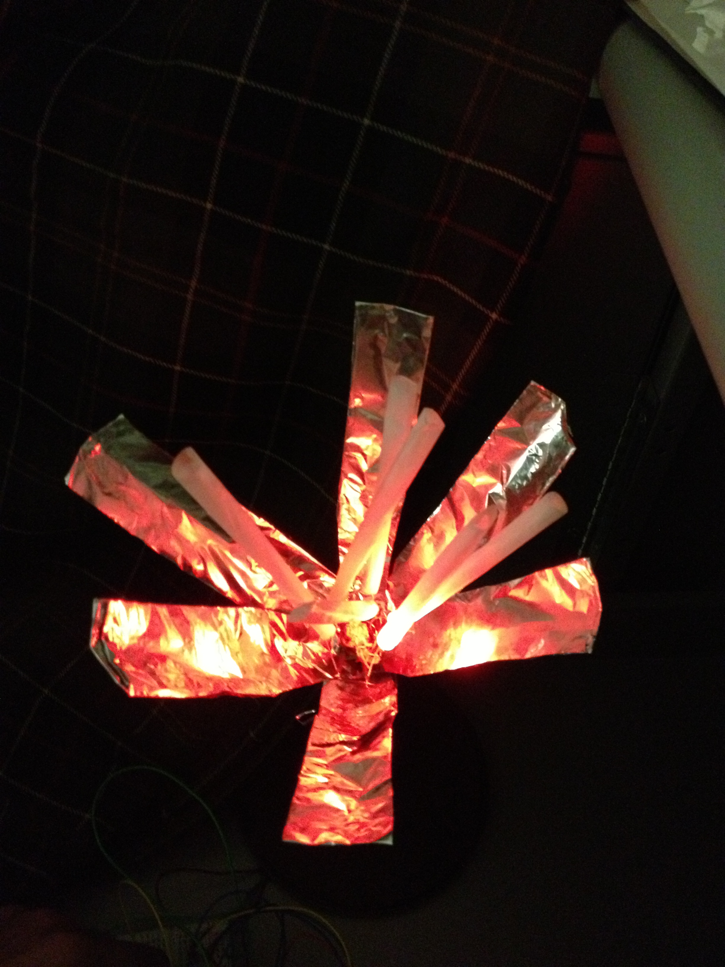
Red LED’s
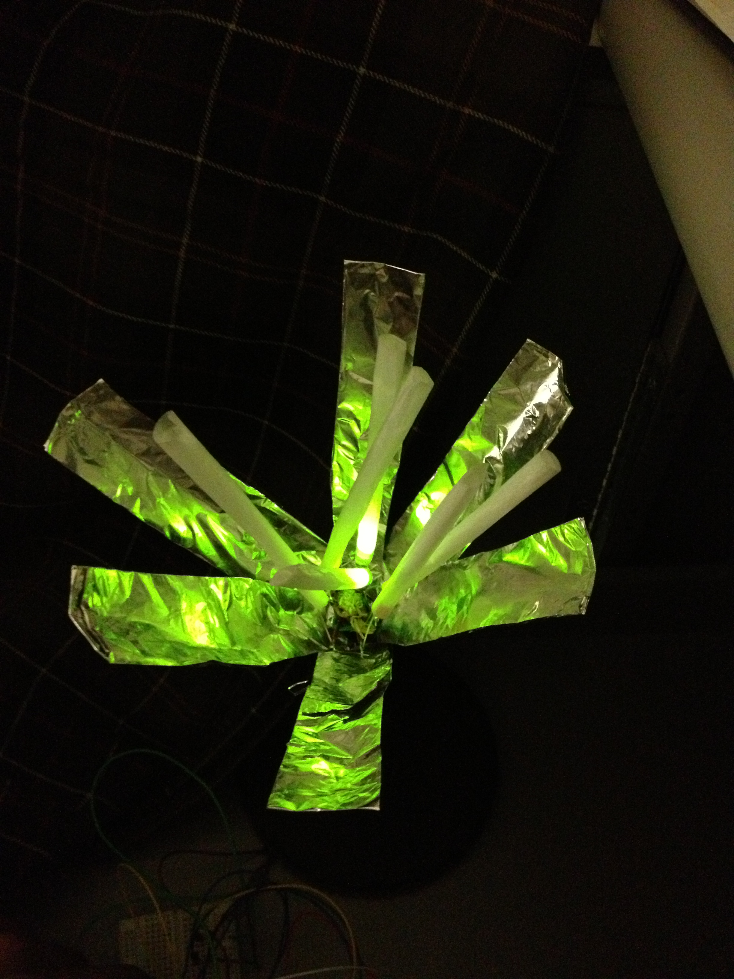
Green LED’s
Demo:
Parts List:
- 6 LED’s (20mA, 2V) – 2 red, 2 yellow, 2 green
- Green and Brown insulated copper wire
3 Compact discs1 Flex sensor- Pack of short-size rolling papers
- 1 roll Aluminium foil
- 3 rotary potentiometers
- 1 Tree branch for support
- CD-holder base (or similar rigid base)
1 Soldering iron3 Alligator clips- 1 Glue gun
- 1 Arduino board
Instructions:
- Start by gluing the wires that will connect the led’s from the top of the branch to the Arduino. Glue the brown wires first. Run the wire along the side of the support leaving about 3″ at the top and about 6″ at the bottom extra for making electrical connections. Then wrap the green wire around these wires and glue it, again leaving extra wire at the ends for connections.
- Cut a hole in the center of the CD-holder base and run all the wires through it. Make the support stand upright on the base and glue the bottom to fix it in position.
- For each pair of LED’s of the same color, solder the negative of one to the positive of the other. These pair’s will act as the building blocks for the LED pattern at the top of the support. Strip the ends of all the wires at the top of the support. For each pair of LED’s, connect the positive end to one of the brown wires and the negative end to the green wire (which acts as ground). Make a note of which brown wire connects to which color.
- Connect the other end of the wires to the Arduino pins through a 330 ohm resistor in series with each, in the following manner –
Red LED’s – Pin 9
Green LED’s – Pin 10
Yellow LED’s – Pin 11. - Make conical light shades using the rolling papers and cover each LED with one conical shade.
- Cut out 6 – 5″ X 1″ strips of aluminium foil and layer them to make each strip stiffer. Then, attach each of the strips around the support in a floral pattern, with the bottom end taped below the LED’s and the upper ends hanging loose.
- Attach the leftmost pin of each potentiometer to ground, and the rightmost pin of each to 5V. Attach the middle pins to A0, A1 and A2 for yellow, green and red led’s respectively.
Source Code:
/* Radiate
* Group: Yaared Al-Mehairi, Kuni Nagakura, Farhan Abrol, Joe Turchiano
* ------------------
* The circuit:
* LED's (red, green, and yellow) are attached from digital pins 8, 9,
* and 10 to ground. We connect potentiometers to analog in pins 9,10,11.
*/

// These constants won't change. They're used to give names
// to the pins used:
const int analogInPinY = A0; // Analog input pin that the potentiometer is attached to
const int analogInPinG = A1; // Analog input pin that the potentiometer is attached to
const int analogInPinR = A2; // Analog input pin that the potentiometer is attached to

const int analogOutPinY = 9; // Analog output pin that the LED is attached to
const int analogOutPinG = 10; // Analog output pin that the LED is attached to
const int analogOutPinR = 11; // Analog output pin that the LED is attached to

int sensorValueY = 0; // value read from the pot
int sensorValueG = 0; // value read from the pot
int sensorValueR = 0; // value read from the pot

int outputValueY = 0; // value output to the PWM (analog out)
int outputValueG = 0; // value output to the PWM (analog out)
int outputValueR = 0; // value output to the PWM (analog out)

void setup() {
// initialize serial communications at 9600 bps:
Serial.begin(9600);
}

void loop() {
// read the analog in value:
sensorValueY = analogRead(analogInPinY);
sensorValueG = analogRead(analogInPinG);
sensorValueR = analogRead(analogInPinR);

// map it to the range of the analog out:
outputValueY = map(sensorValueY, 0, 1023, 0, 255);
outputValueG = map(sensorValueG, 0, 1023, 0, 255);
outputValueR = map(sensorValueR, 0, 1023, 0, 255);

// change the analog out value:
analogWrite(analogOutPinY, outputValueY);
analogWrite(analogOutPinG, outputValueG);
analogWrite(analogOutPinR, outputValueR);

// wait 2 milliseconds before the next loop
// for the analog-to-digital converter to settle
// after the last reading:
delay(2);
}