
1) Names: Philip Oasis, Alice Fuller, Gene Merewether, and Rodrigo Menezes
2) Group Number: 6
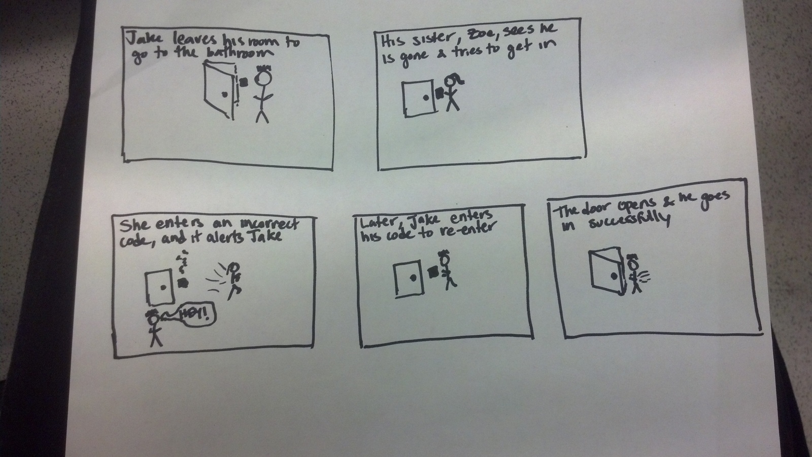
3) We built a sensor-based authentication system. The idea behind it is that you enter in a code the first time, and then on subsequent uses you have to enter in the same code. We had three sensors: two potentiometers which had to be turned the correct degree and one slide sensor which had to have your finger placed in the correct position. The end result was really great. The correct position, given a small amount of error could be found again, but a knowledge of the initial code was still needed. When you got the code correct a green light went off, and when you got it wrong a buzzer went off. I enjoyed the fact that you had to have your finger in the correct position on the sensor while you pushed the button, the multiple tasks reminds me of cool authentication systems that you see in movies. It might have been nice to have things in a prettier display; we could have obscured the wires better, had the sensors further apart to improve ease of movement, had written instructions. This would have also been much better if there was an actual lock to unlock.
4)
This is a simple reaction game in which the buzzer sounds, the user hits the button as quickly as possible, and the LED then lights up to give them feedback on how quickly they reacted.

This is a memory game in which the user hits buttons to recreate the order the LED’s flashed, and the sequence gets one light longer for each round the user gets correct.
This is a racing reaction game in which the LED flashes red, yellow, and green and then the user tries to hit the button as soon as possible after a green. The buzzer would go off in the event of a false start, and the LED would light up with a color to indicate the reaction time.
5) Storyboard:
7) Parts List
- 2 potentiometers
- 1 slide sensor
- 1 button
- 1 buzzer
- 1 green LED
- 2 bread boards
- 1 arduino
- 2 330Ω resistor
- 1 10kΩ resistor
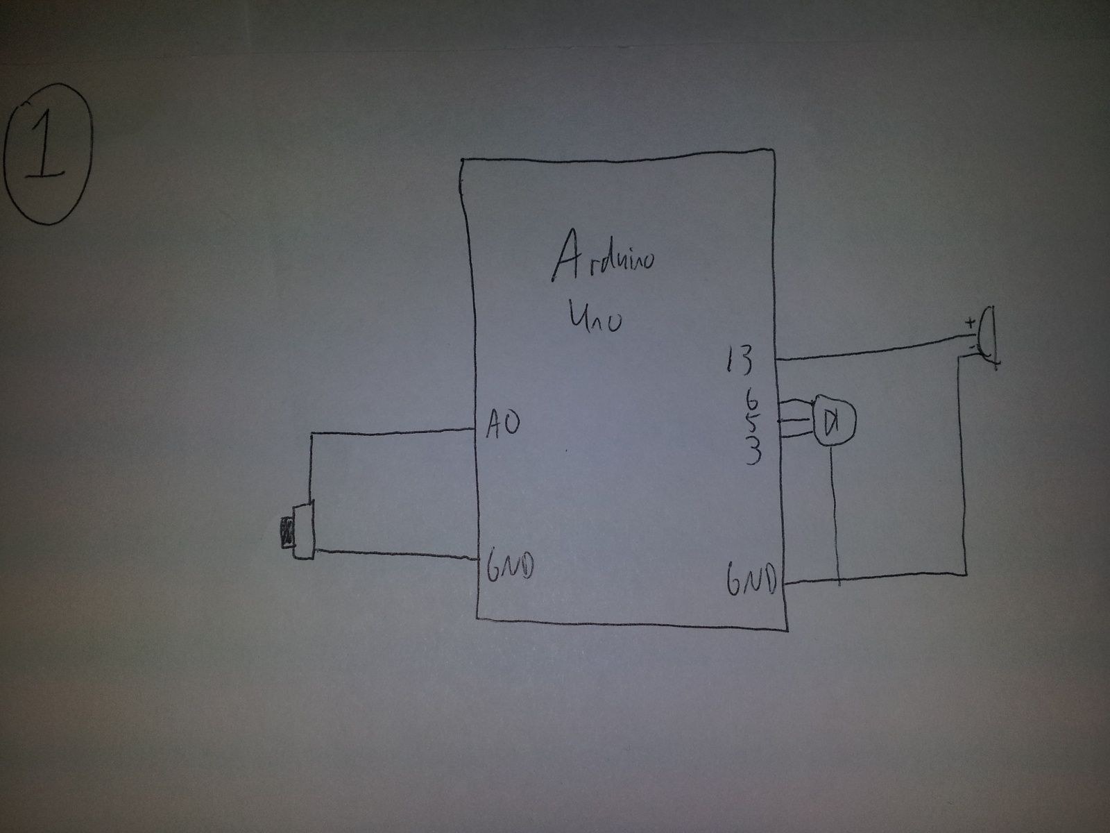
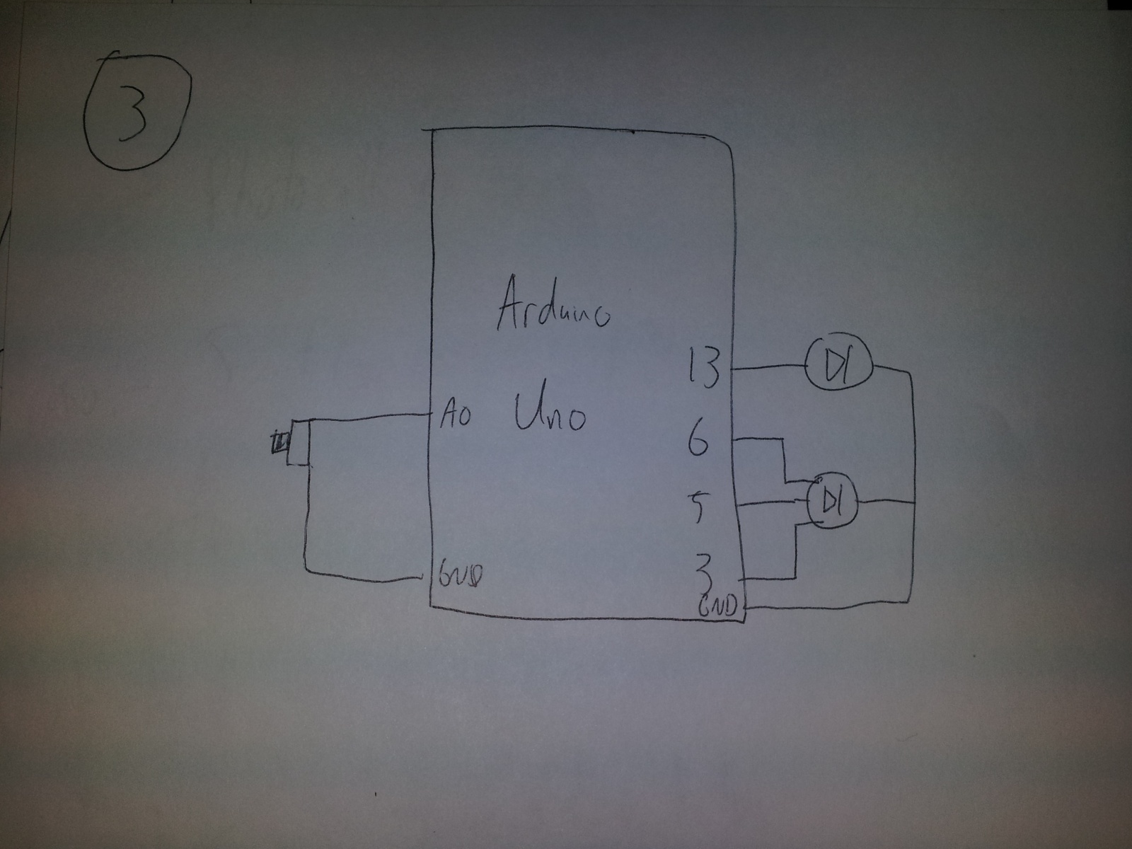
8) Directions
Attach these all on one breadboard:
Attach one potentiometer to pin 0 on the arduino, the other to pin 1. Attach the button to pin 2, the buzzer to pin 3, and the led to pin 5. There should be a 330 ohm resistor attached with the led and the buzzer, and a 10k ohm to the button. The two potentiometers should be next to each other at the front, the button should be just behind them, and the buzzer and led are at the back of the breadboard. On the separate smaller breadboard place the slide sensor and connect it to pin 2.
9) Source Code
const int potentialPin1 = 0;
const int potentialPin2 = 1;
const int slidePin = 2;
const int buttonPin = 2;
// pull-down resistor; LOW is not pressed
const int buzzerPin = 3;
const int ledPin = 5;
const int tolerance = 64;
const int buzzerTone = 20;
int lock1 = -1;
int lock2 = -1;
int lock3 = -1;
void setup()
{
pinMode(buttonPin, INPUT);
pinMode(buzzerPin, OUTPUT);
pinMode(ledPin, OUTPUT);
Serial.begin(9600);
while (digitalRead(buttonPin) == LOW) // wait until button is pressed
{
delay(100);
}
// enter in lock code
lock1 = analogRead(potentialPin1);
lock2 = analogRead(potentialPin2);
lock3 = analogRead(slidePin);
digitalWrite(ledPin, HIGH);
Serial.print(“Potentiometer1 = “);
Serial.println(lock1);
Serial.print(“Potentiometer2 = “);
Serial.println(lock2);
Serial.print(“Slide sensor = “);
Serial.println(lock3);
}
void loop()
{
int buttonState = digitalRead(buttonPin);
int potentialState1 = analogRead(potentialPin1);
int potentialState2 = analogRead(potentialPin2);
int slideState = analogRead(slidePin);
Serial.print(“Potentiometer1 = “);
Serial.println(potentialState1);
Serial.print(“Potentiometer2 = “);
Serial.println(potentialState2);
Serial.print(“Slide sensor = “);
Serial.println(slideState);
if (buttonState == HIGH) // pressed
{
if ((potentialState1 < (lock1 + tolerance)) &&
(potentialState1 > (lock1 – tolerance)) &&
(potentialState2 < (lock2 + tolerance)) &&
(potentialState2 > (lock2 – tolerance)) &&
(slideState < (lock3 + tolerance)) &&
(slideState > (lock3 – tolerance)))
{
digitalWrite(ledPin, HIGH);
delay(1000);
}
else // not correct code
{
digitalWrite(ledPin, LOW);
analogWrite(buzzerPin, buzzerTone);
delay(1000);
}
}
digitalWrite(ledPin, LOW);
analogWrite(buzzerPin, 0);
}