Group Number
8 What we built
We’ve built a lighting system that reacts to the background light and pressure. We wanted to build a lighting system that automatically dims itself to save energy when there’s enough background light, and only turns on if necessary e.g. when a person is standing in front of the door thereby applying pressure to the sensor. Our system only turns on the LED lights when there’s pressure and low background light as intended. We picked arbitrary thresholds for background light and pressure, but in the future, we’d like to select these values after a more systematic analysis. Sketches
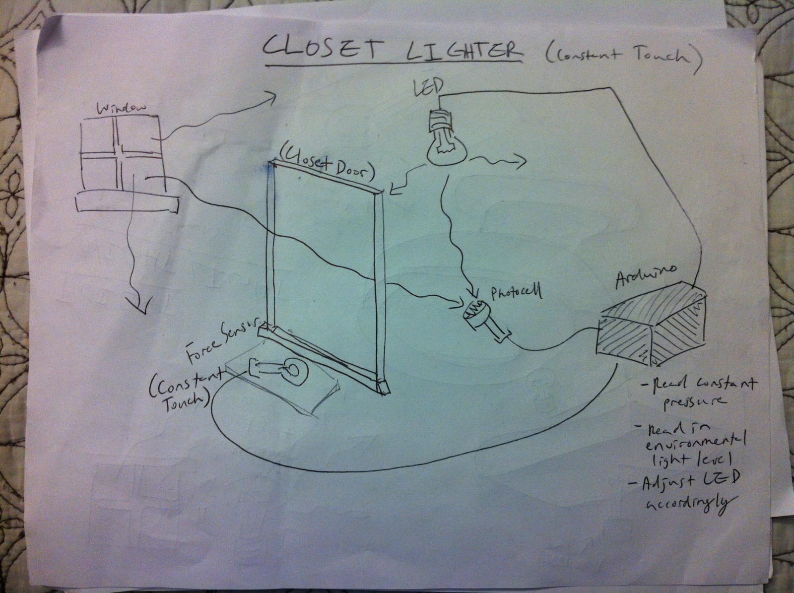
Our idea applied to a closet. Depending on the background light, the light bulb adjusts its brightness accordingly. Also, it only turns on when a person is standing in front of the closet looking for something, thereby saving energy.
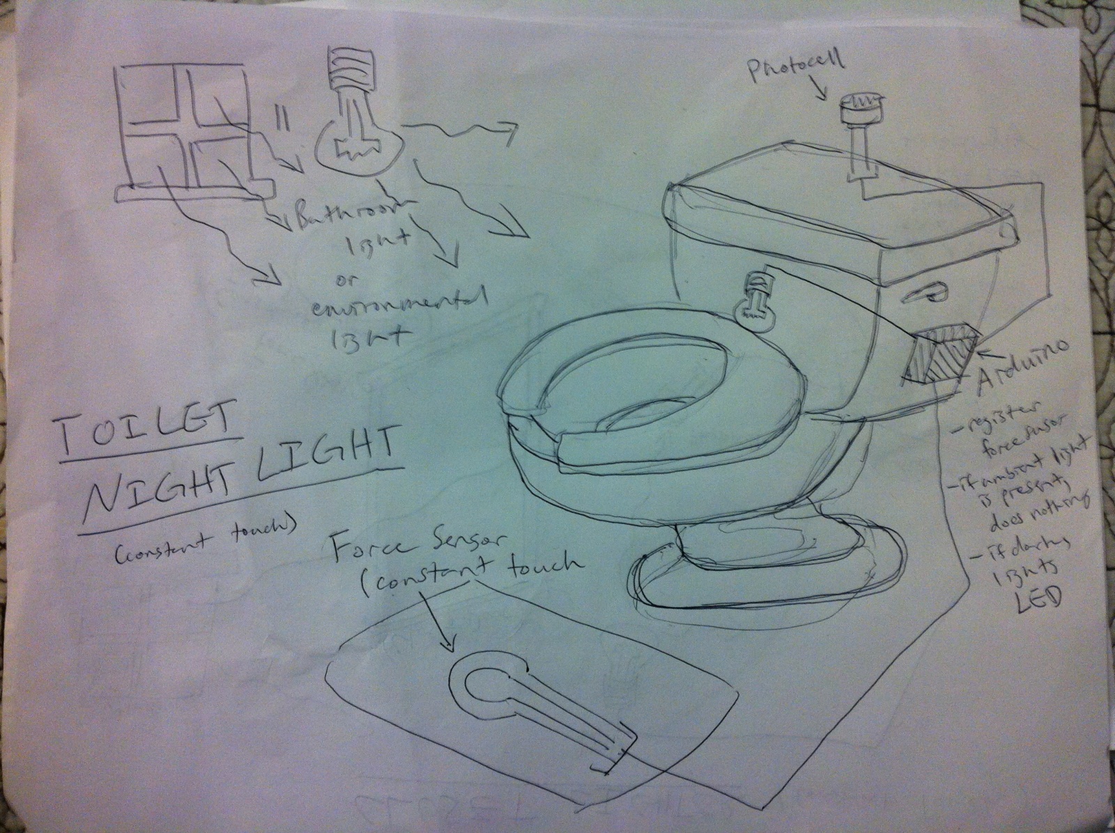
Our idea applied to the toilet. Depending on the background light, the brightness of the room is adjusted. Also, the light turns on only when you’re sitting in the toilet.
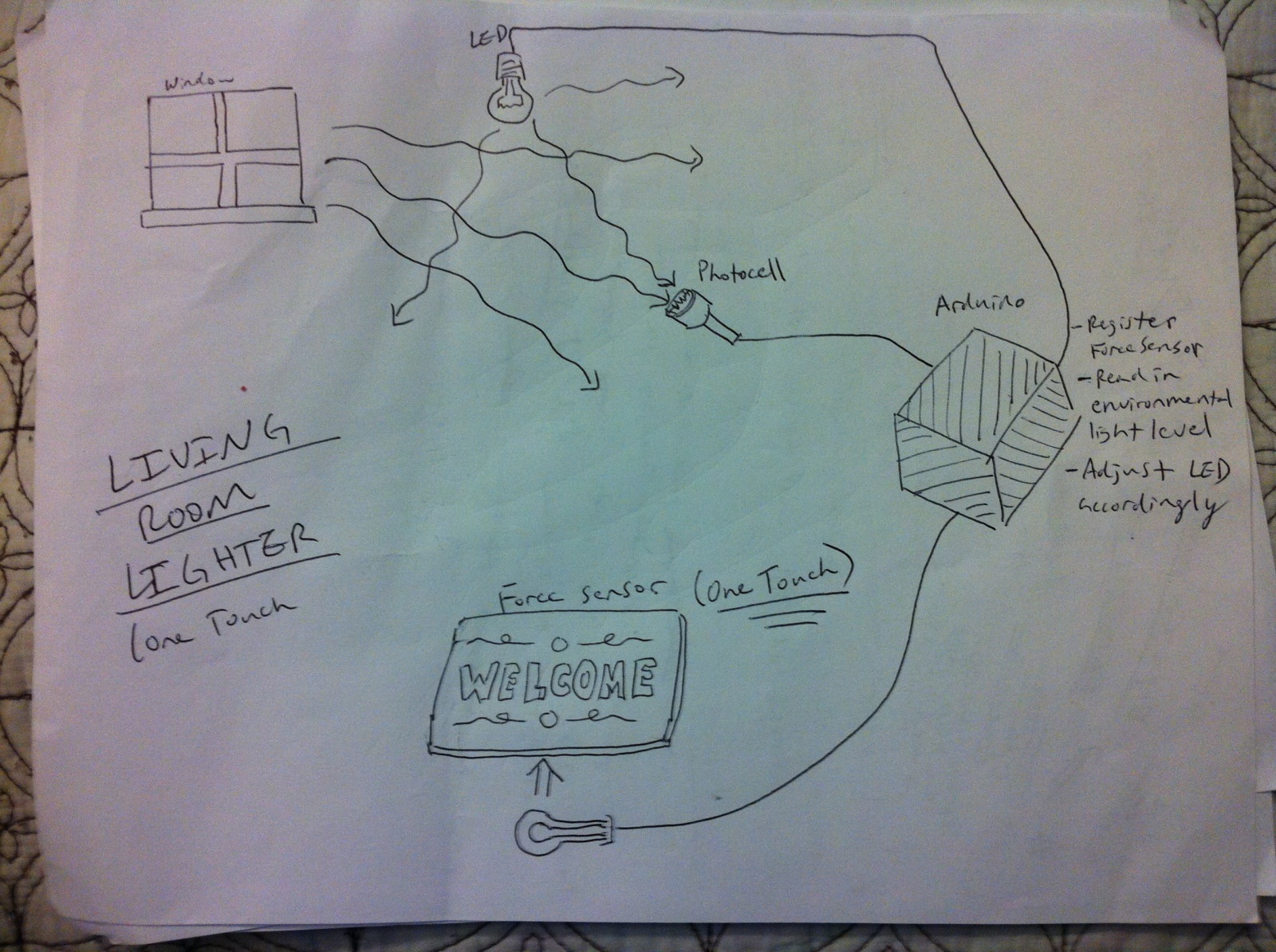
Our idea applied to the entrance of a residential house. Only when someone is standing at the entrance does the light turn on. Also, it adjusts its brightness based on the background light.
Storyboard Pictures and Video
This slideshow requires JavaScript.
List of parts
2 10K Ohm resistors
2 LED Lights
1 Force-sensing Resistor
1 Photo Sensor
Instructions
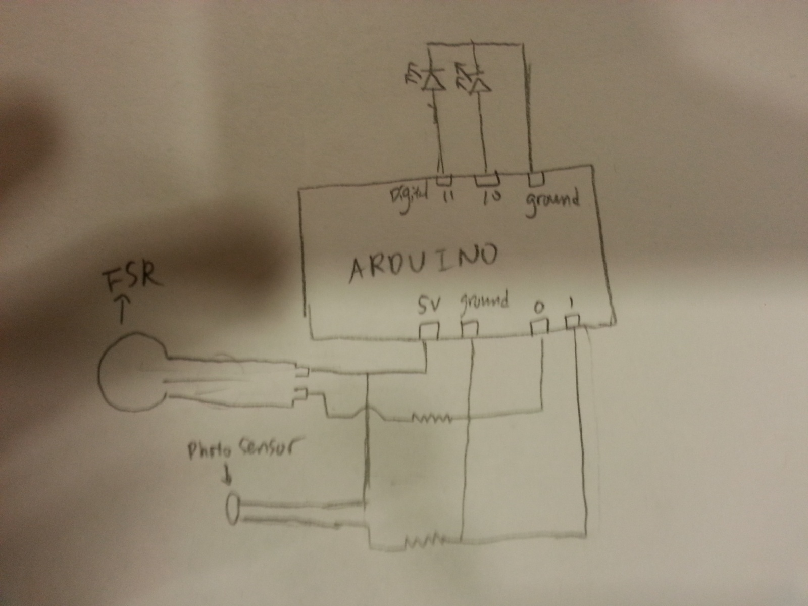
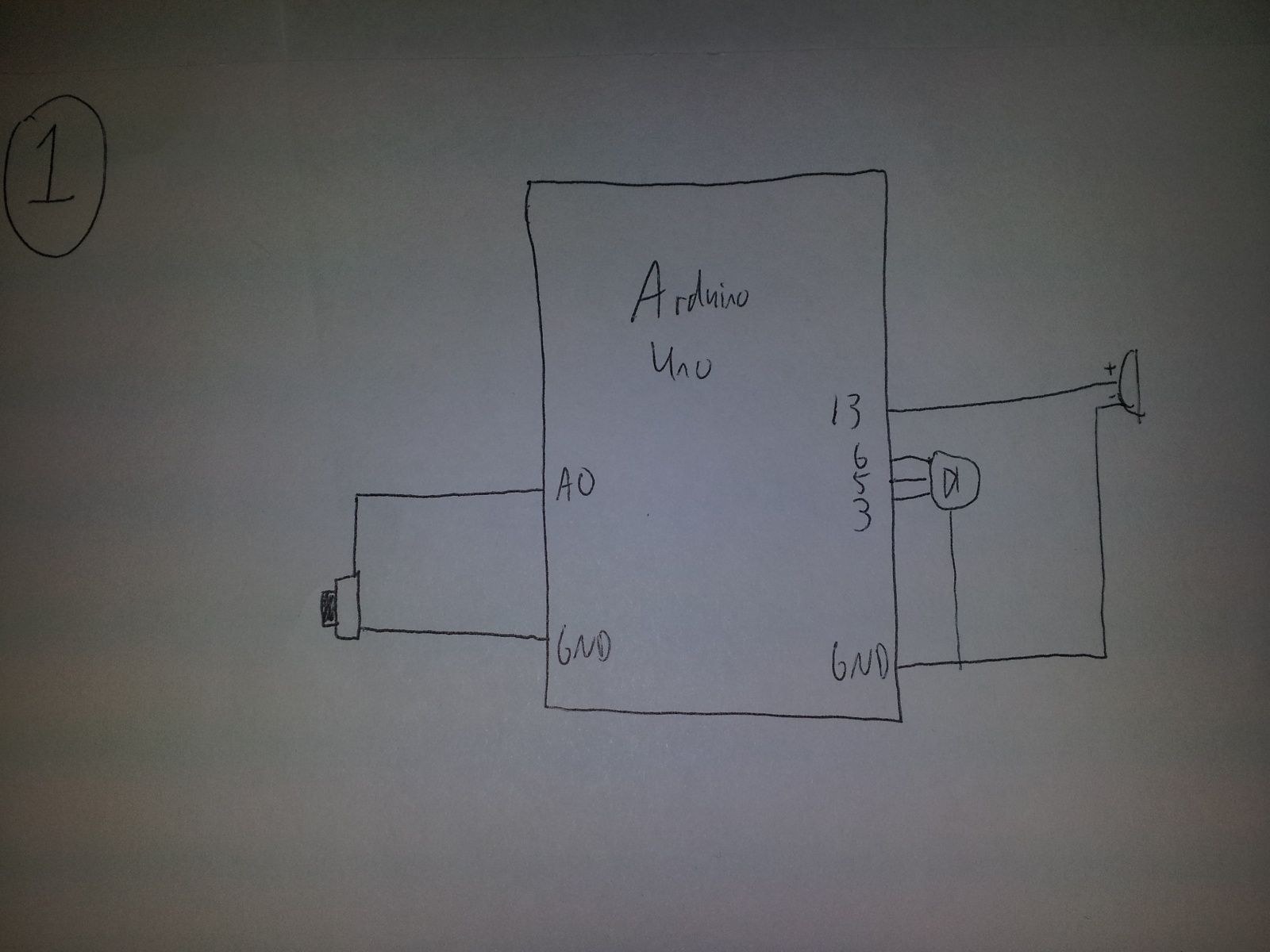
Complete the circuit as shown in the picture below.
Code
// pin numbers for LED
const int greenLED = 11;
const int yellowLED = 10;
const int lightSensor = 0;
const int forceSensor = 1;
const int LIGHT_MAX = 255;
const int FORCE_THRESHOLD = 400;
const int LIGHT_THRESHOLD = 100;

// variables
int light = 0;
int force = 0;

void setup() {
  pinMode(greenLED, OUTPUT);
  pinMode(yellowLED, OUTPUT);
}

void changeLight(int light) {
  analogWrite(greenLED, light);
  analogWrite(yellowLED, light);
}

void loop() {
  changeLight(0);
  light = analogRead(lightSensor);
  force = analogRead(forceSensor);
  if (light < LIGHT_THRESHOLD && force > FORCE_THRESHOLD) {
    changeLight(LIGHT_MAX);
  }
}
Kevin Lee, Saswathi Natta, Andrew S. Boik, Brian W. Huang
Group Number 16
Description:
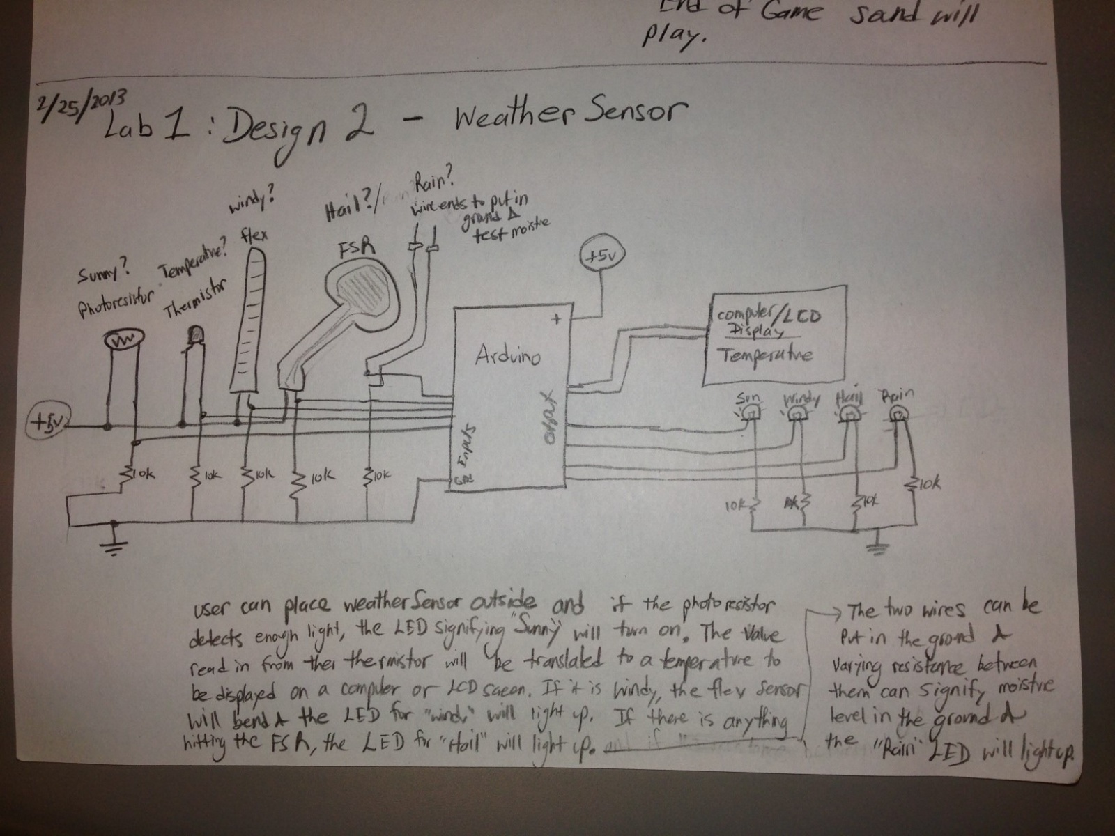
We built a weather detector using various sensors to detect different weather conditions. We use a flex sensor for detecting wind as it blows on it, an FSR for detecting hail as it hits it, a photocell for detecting sunlight, a Variable You-sistor for detecting rain when electricity is conducted between the two bare ends of the jumper wires through water on the ground, and a thermistor for detecting temperature. The temperature is printed to the screen, while the other sensors have LEDs that correspond to them. The LED will turn on if the corresponding sensor reads a value that exceeds a threshold, in which case, the appropriate weather condition has been detected. We selected this project because we believe each sensor naturally has a corresponding component of weather that it is suited for detecting, and being able to detect weather conditions is a very useful, practical application of the tools provided in this lab. In our opinion, the project was largely a success. We liked how our light sensor, flex sensor, photocell, and themistor all detect their weather components accurately. We however think that our FSR is not well suited as a hail sensor. This is because it seems to require a fair bit of weight to be on top of it to register any significant readings, so it is uncertain whether ice will be detected on top of it.. Realistically, the FSR would also probably break if hail were to fall directly on top of it. Had we had time, we also would have designed a container for our device so that the device doesn’t become damaged under intense weather conditions.
Sketches of Early Ideas
A weather detector that detects various weather conditions.
A primitive instrument with continuously changing pitch and volume.
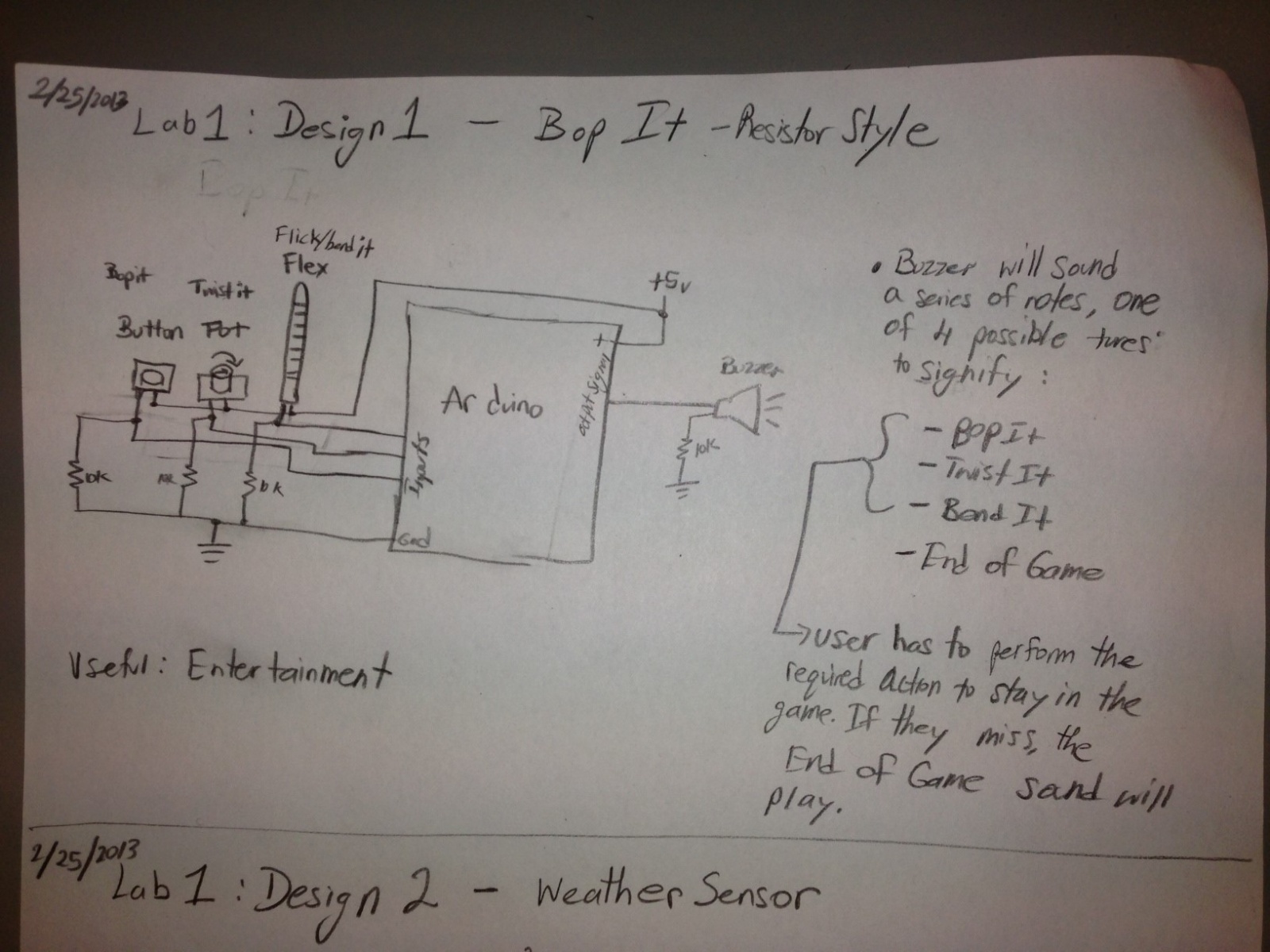
A version of the bop-it game.
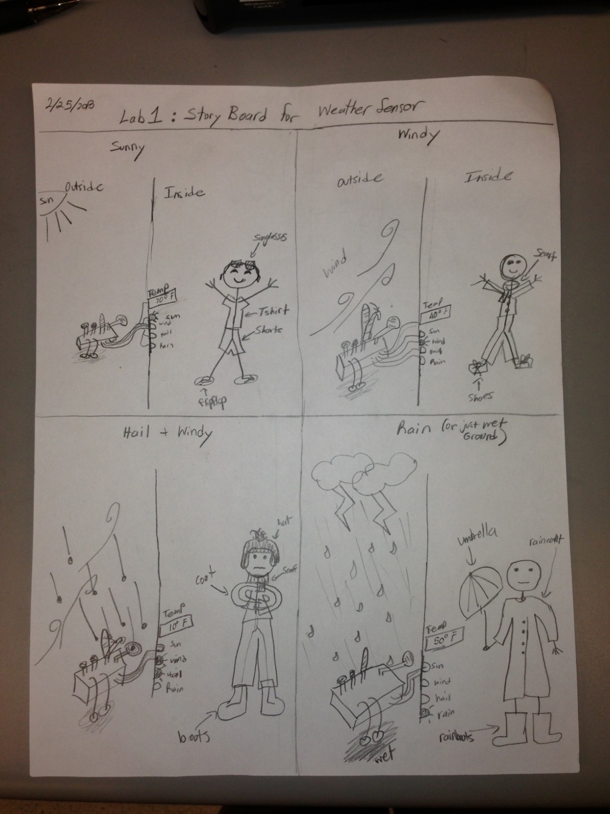
Storyboard for Weather Detector:
Storyboard for weather detector.
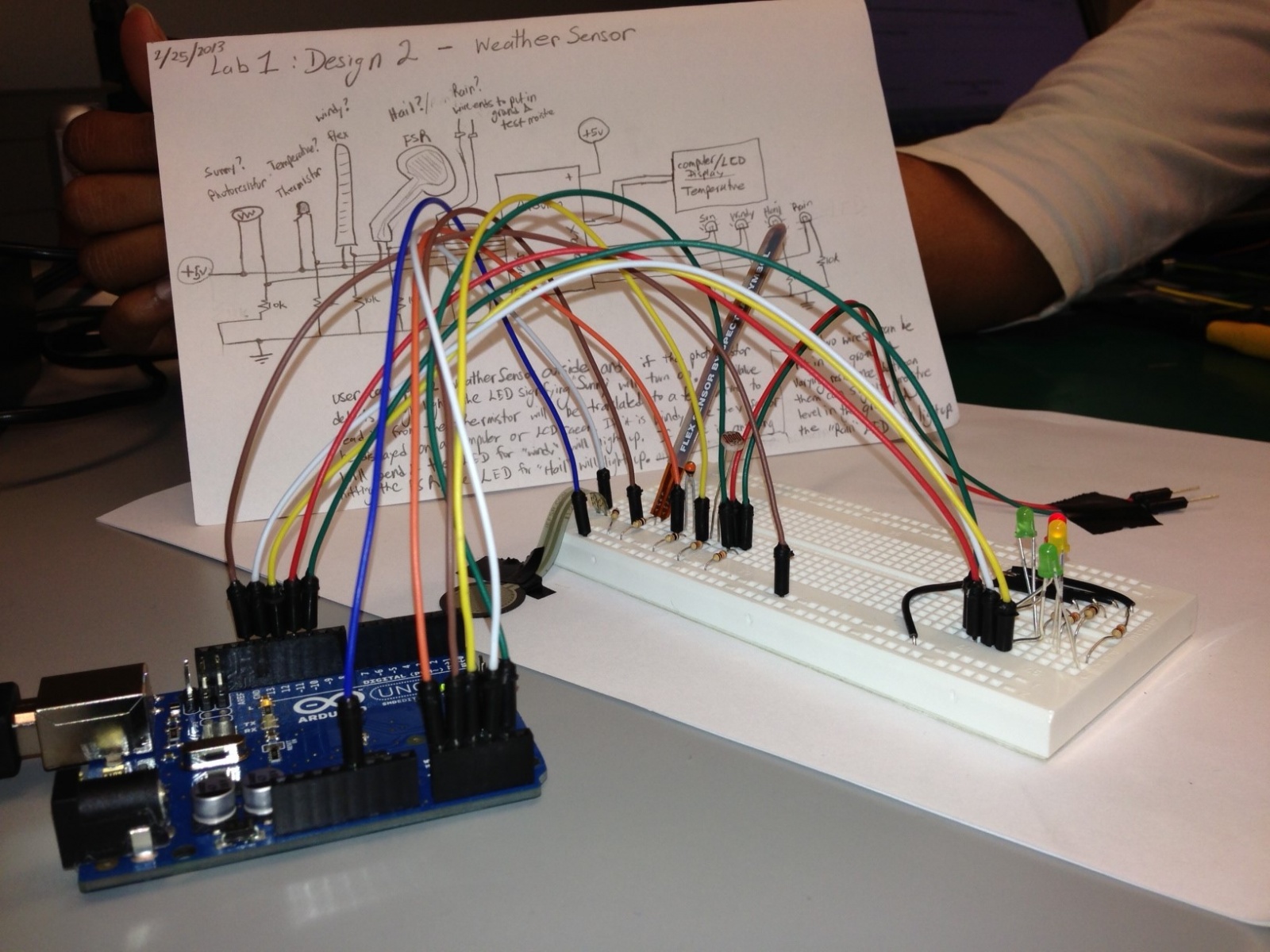
Final System – Weather Detector:
Our weather detector with design sketch in view.
Close up view of our weather detector.
Photo of our weather detector with sail for wind detection in view.
List of parts:
– Arduino
– 4 LEDs
– 9 10k Resistors
– FSR
– Flex Sensor
– Thermistor
– Photocell
– Cardboard and paper
– Jumper wires
Instructions:
1. Setup LEDs and sensors
-Place the long end of each of the 4 LEDs to the chosen Arduino digital output pin and the shorter end to ground through 10k resistor
-Setup FSR, Flex sensor, Thermistor, Photocell, and Variable You-sistor (two jumper wires). All sensors are wired with a voltage divider, using 10k resistor to ground, between one pin connected to 5V power and the other pin connected to an Arduino analog input pin to detect the resistance. Each sensor gets its own analog input. Tape cardboard to the base of the flex sensor for flexibility and a paper sail to the top of it to make it sensitive to wind.
2. Test baseline for sensors and adjust thresholds as necessary
-Once the sensors are connected, with the proper (~10K) voltage divider connected to power on one pin and the other pin connected to the Arduino, the Arduino software will display it’s reading of the input. For each sensor, test it with appropriate weather conditions to see how the readings change to determine appropriate thresholds.
-FSR, Flex sensor, Photocell, and Variable You-sistor all have corresponding LEDs that will turn on when threshold is passed. FSR LED signifies hail, flex sensor LED signifies wind, photocell LED signifies sunlight, and Variable You-sistor LED signifies rain.
Code:
/* Weather sensor for L2
 * Lab Group 16 (old 21):
 * Andrew Boik (aboik@)
 * Brian Huang (bwhuang@)
 * Kevin Lee (kevinlee@)
 * Saswathi Natta (snatta@)
 */

// pin inputs
int thermistor_pin = A0;
int flex_pin = A1;
int photo_pin = A2;
int fsr_pin = A3;
int wet_pin = A4;

// led outputs
int wind_led = 13;
int sunny_led = 12;
int hail_led = 11;
int rain_led = 10;

// thresholds for led light-up
int wind_thresh = 300;
int sunny_thresh = 800;
int hail_thresh = 10;
int rain_thresh = 10;

// led max brightness
int led_max_val = 255;
// led min brightness
int led_min_val = 0;
// delay time
int delay_time = 500;

// timeouts for hail/rain and time since last event
unsigned long hail_timeout = 5000;
unsigned long rain_timeout = 5000;
unsigned long time_since_last_rain;
unsigned long time_since_last_hail;

void setup(void) {

 time_since_last_rain = rain_timeout;
 time_since_last_hail = hail_timeout;

 Serial.begin(9600);
 pinMode(wind_led, OUTPUT);
 pinMode(sunny_led, OUTPUT);
 pinMode(hail_led, OUTPUT);
 pinMode(rain_led, OUTPUT);
}

void loop(void) {

  // get readings
 int temperature = analogRead(thermistor_pin);
 double true_temp = (temperature - 345.684) / 5.878;
 int wind = analogRead(flex_pin);
 int sunny = analogRead(photo_pin);
 int hail = analogRead(fsr_pin);
 int rain = analogRead(wet_pin);

// print out vals from sensors
 Serial.print("Temperature = ");
 Serial.println(true_temp);
 Serial.print("Wind = ");
 Serial.println(wind);
 Serial.print("Sunny = ");
 Serial.println(sunny);
 Serial.print("Hail reading = ");
 Serial.println(hail);
 Serial.print("Rain reading = ");
 Serial.println(rain);
 Serial.println();

 // led light-up
 if (wind > wind_thresh)
   digitalWrite(wind_led, led_max_val);
 else
   digitalWrite(wind_led, led_min_val);
 if (sunny > sunny_thresh)
   digitalWrite(sunny_led, led_max_val);
 else
   digitalWrite(sunny_led, led_min_val);
 if (hail > hail_thresh) {
   time_since_last_hail = 0;
   analogWrite(hail_led, 255);
 }
 else if (time_since_last_hail < hail_timeout) {    Serial.print("time_since_last_hail = ");    Serial.println(time_since_last_hail);    time_since_last_hail += delay_time;    analogWrite(hail_led, 255);  }  else {    time_since_last_hail += delay_time;    analogWrite(hail_led, 0);  }  if (rain > rain_thresh) {
   time_since_last_rain = 0;
   analogWrite(rain_led, 255);
 }
 else if (time_since_last_rain < rain_timeout) {
   Serial.print("time_since_last_rain = ");
   Serial.println(time_since_last_rain);
   Serial.println();
   time_since_last_rain += delay_time;
   analogWrite(rain_led, 255);
 }
 else {
   time_since_last_rain += delay_time;
   analogWrite(rain_led, 0);
 }

 delay(delay_time);
}
Team Deep Thought (Group 25):
Vivian Qu
Neil Chatterjee
Alan Thorne
Harvest Zhang
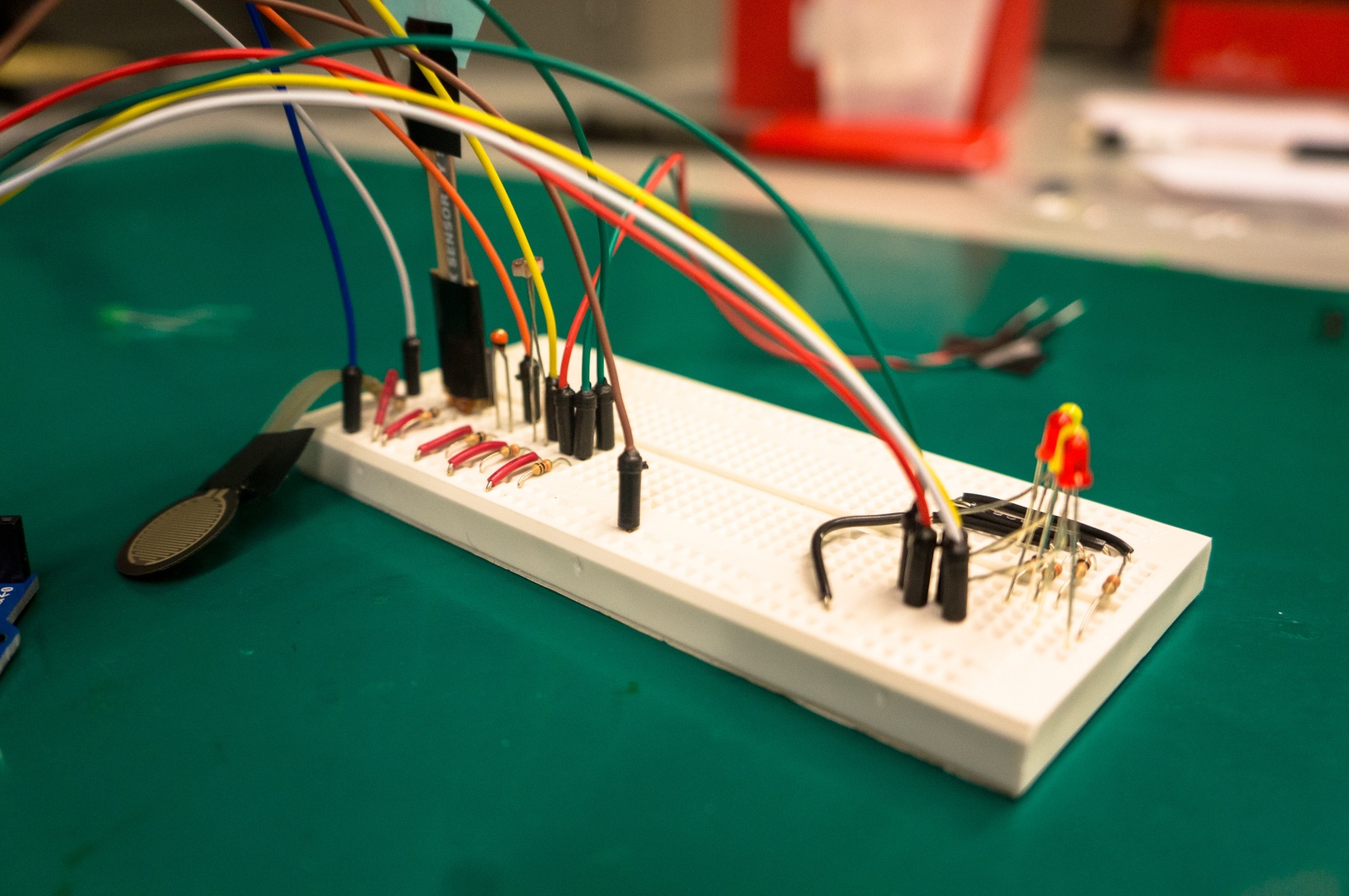
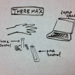
We built a device that mimics a theremin, controlled using a light sensor and touch sensitive slider (softpot). The goal of the device is to be a fun, interactive way to play music using the sensors. This device also could conceivably be used to teach young students about the physics of sound waves, since our visualizer shows the actual wave form changing in proportion to the user’s actions! One issue we had is that we needed to keep a finger on the softpot at all times or else there were spikes in the sound because the readings need to stabilize. This would be an aspect we would want to fix to streamline the experience. Future improvements could include adding buttons to change the tone of the sound and figure out how to control two different wave forms simultaneously. Otherwise, the device successfully works and allows the user to control the graphic sine wave to create different sounds.
I. Photos & Videos:
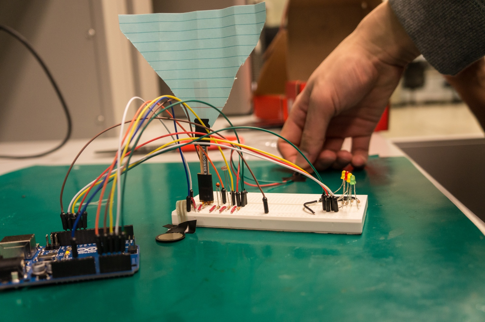
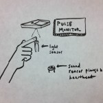
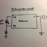
Pulse Monitor — Uses a light sensor to detect the changes in light filtered through the skin, detecting the heartbeat. Emits sound from the buzzer to match the heartbeat.
Pulse Monitor
Pulse Monitor Circuit
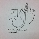
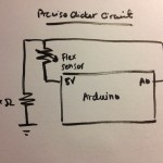
Precise Clicker — The device uses a flex sensor as a discreet clicker for presentations.
Precise Clicker
Precise Clicker Circuit
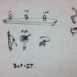
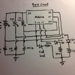
Bop-It — A fun interactive game based on the “Bop-It” games, where LED lights signal which sensor (Flex/FSR/Potentiometer) to manipulate.
Bop-It
Bop-It Circuit
Theremax — Uses the softpot and light sensor to control the frequency and amplitude of the sound wave.
Theremax
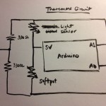
Theremax Circuit
We chose to implement the Theremax idea, coming up with the following storyboard for why a user would want to interact with the device.
Here’s a video of our device at work:
The touch sensitive slider (softpot) controls the frequency and the light sensor controls the amplitude. Sliding down on the slider increases the frequency, and covering the light sensor (less light input) reduces the frequency.
II. Parts Used
Arduino Uno x1
Photocell x1
Softpot x1
330 ohm resistors x2
Breadboard
Wires
III. Setup
Connect the middle lead of the softpot to analog input (we used A0) and the leftmost lead to 5V and the third through a 330 ohm resistor to ground. Connect the left leg of the photocell to 5V and the other leg is connected to both analog input (we used A1) and through a resistor to ground. Download the source code, using Arduino and Processing. Upload the code to the Arduino and voila!
IV. Source Code
ARDUINO CODE
// Lab 1: Theremax
// Arduino code to read user input from softpot and thermoresistor.

// Frequency
int freq;
// Amplitude
int ampl;
// Receiving input from analog ports 0 and 1.
int thermo = 0;
int softpot = 1;

void setup(void) {
// Send input data to Processing via the Serial monitor.
Serial.begin(9600);
}

void loop(void) {
  // Read from input.
  ampl = analogRead(thermo);
  freq = analogRead(softpot);

  ampl = map(ampl, 0, 260, 0, 100);
  freq = map(freq, 0, 500, 0, 100);

  // Send data to Processing.
  Serial.write(ampl);
  Serial.write(freq);

  delay(500);
}
ARDUINO CODE
// Lab 1: Theremax
// Processing code to output sound and graphically show the oscillator.

import ddf.minim.*;
import ddf.minim.signals.*;
import processing.serial.*;
Serial port;
Minim minim;
AudioOutput out;
SineWave sine;
int volume;
int slider;

void setup()
{
  size(512, 200, P3D);
  port = new Serial(this, Serial.list()[0], 9600);
  minim = new Minim(this);
  // Get a line out from Minim, default bufferSize is 1024, default sample rate is 44100, bit depth is 16
  out = minim.getLineOut(Minim.STEREO);
  // Create a sine wave Oscillator, set to 440 Hz, at 0.5 amplitude, sample rate from line out
  sine = new SineWave(440, 0.9, out.sampleRate());
  // Set the portamento speed on the oscillator to 200 milliseconds
  sine.portamento(200);
  // Add the oscillator to the line out
  out.addSignal(sine);
  volume = 0;
  slider = 0;
}

void draw()
{
  // Compensate for variable readings at the extremes.
  if (port.available() > 0 )
  {
    volume = port.read();
    int temp = port.read();
    if (temp >= 0 )
    slider = temp;
  }
  float freq = map(slider, 0, 100, 60, 1500);
  // Change the frequency of the wave.
  sine.setFreq(freq);
  float volout = map(volume, 0, 100, 0, 1);
  // Change the amplitude of the wave.
  sine.setAmp(volout);
  background(0);
  stroke(255);
  // Draw the waveforms
  for(int i = 0; i < out.bufferSize() - 1; i++)
  {
    float x1 = map(i, 0, out.bufferSize(), 0, width);
    float x2 = map(i+1, 0, out.bufferSize(), 0, width);
    line(x1, 50 + out.left.get(i)*50, x2, 50 + out.left.get(i+1)*50);
    line(x1, 150 + out.right.get(i)*50, x2, 150 + out.right.get(i+1)*50);
  }
}
The Processing code relies on the Minim library and is based on the Sine Wave Signal code found here.
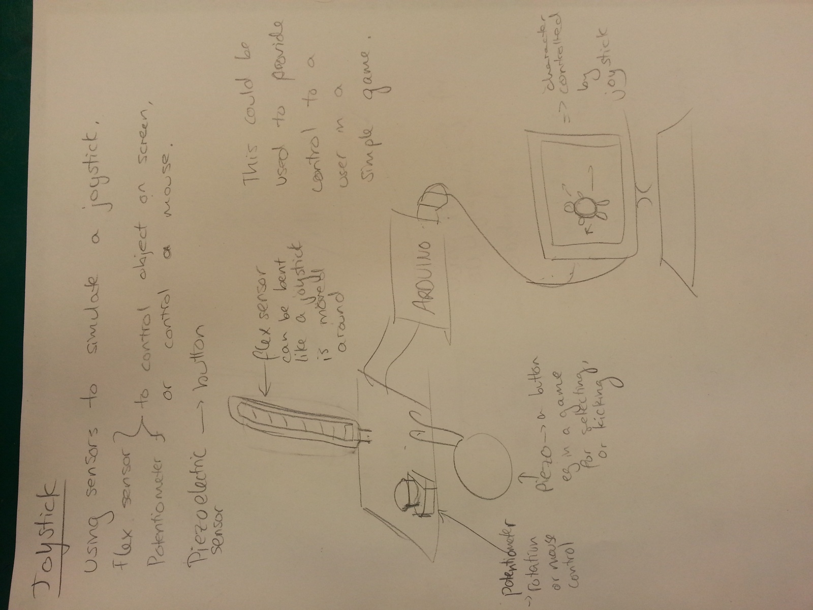
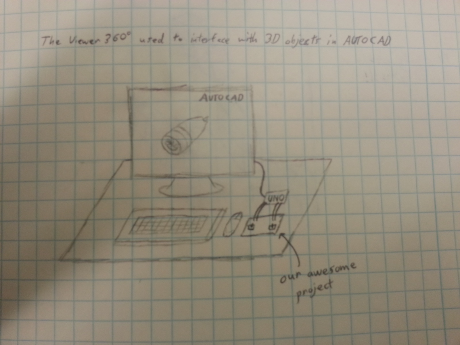
We built a “joystick” controller which, when employed, controlled the movement of a 3D box on the screen. The joystick is made up of two rotary potentiometers. The potentiometers were used to rotate the cube in the y and z direction. One potentiometer controls the y direction, the other in the z. At first, we tried to add in a thin pot sensor to move the box up and down. However, the thin pot was not cooperating with the system and its readings were being affected by the readings of the potentiometer. We had to take this out of the system, because it was causing unexpected movement. Despite this, overall, we believe the project was quite successful. We were able to get rid of jerkiness in the image, so it was a smooth fluid motion and rotation. There was a problem with oversensitivity due to small fluctuations but we were able to fix that. Therefore, given time, we believe this could be made into a reasonable interactive interface. This has AutoCAD applications. 3D designs can be rotated and fully examined with easy movement. 3D images of buildings, monuments, molecules, etc (the opposite of 360 degree camera tours) can be viewed from all angles (e.g. for educational purposes or tours). It could be extended to control, instead of a box, for example a 3D model of a car as a game, or other objects.
Sketches:
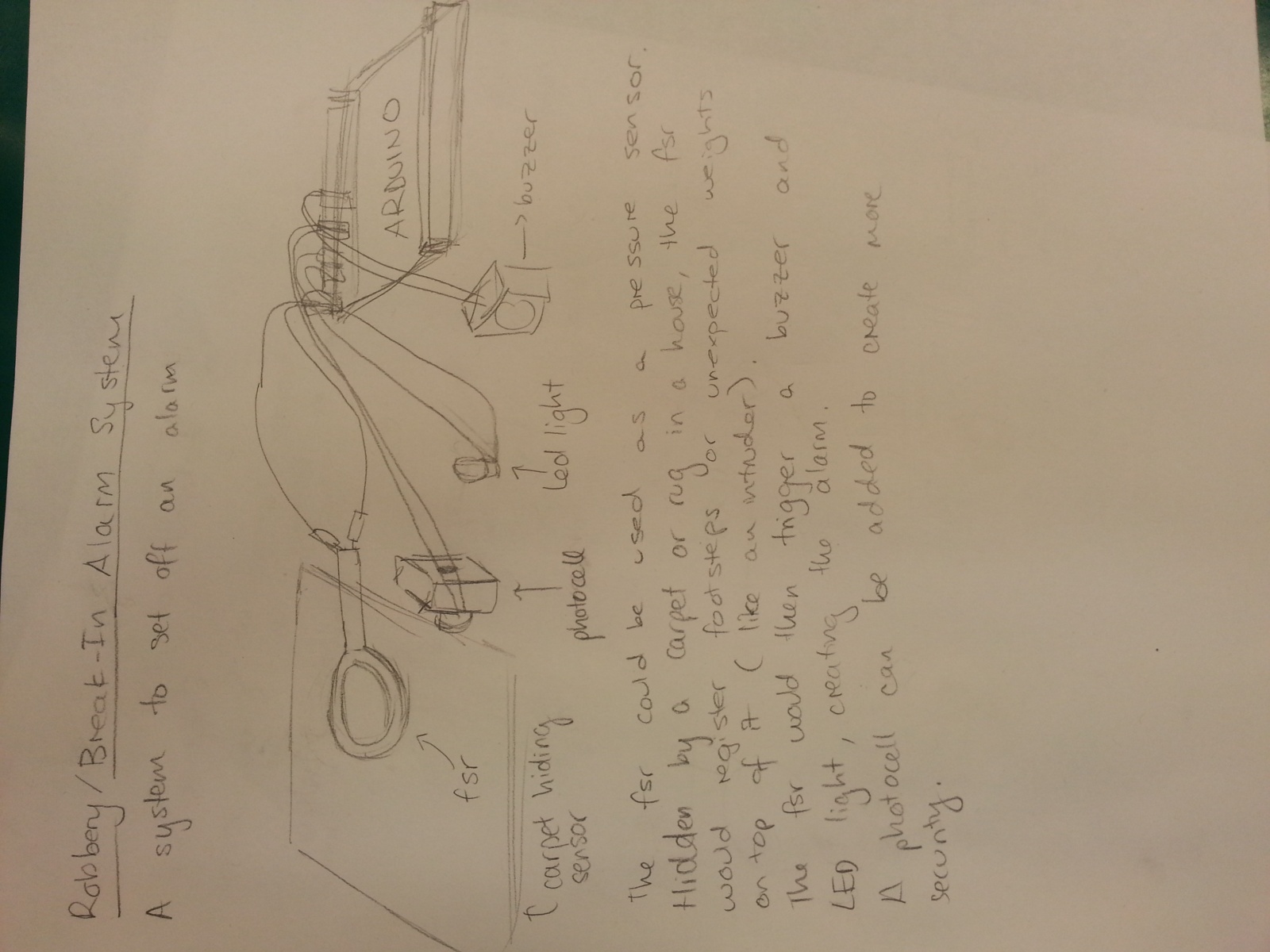
An alarm system which uses an fsr and a photocell to detect unexpected motion to set off a buzzer and LED light as an alarm.
Joystick using flex sensor and potentiometer
Uses a potentiometer to rotate a graphic. Input from sensors go through to Processing.
Storyboard:
Can be used for AutoCAD purposes.
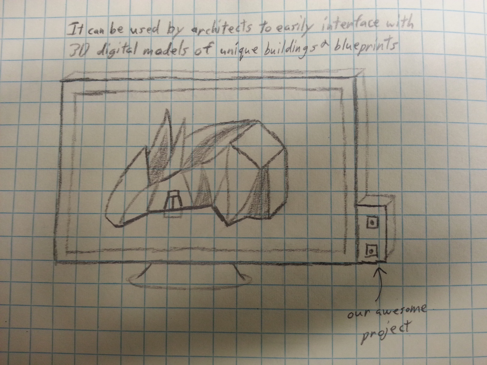
Can be used to examine ideas for building design.
Can be used for 3D gaming purposes, e.g. making tetris more intense in 3D.
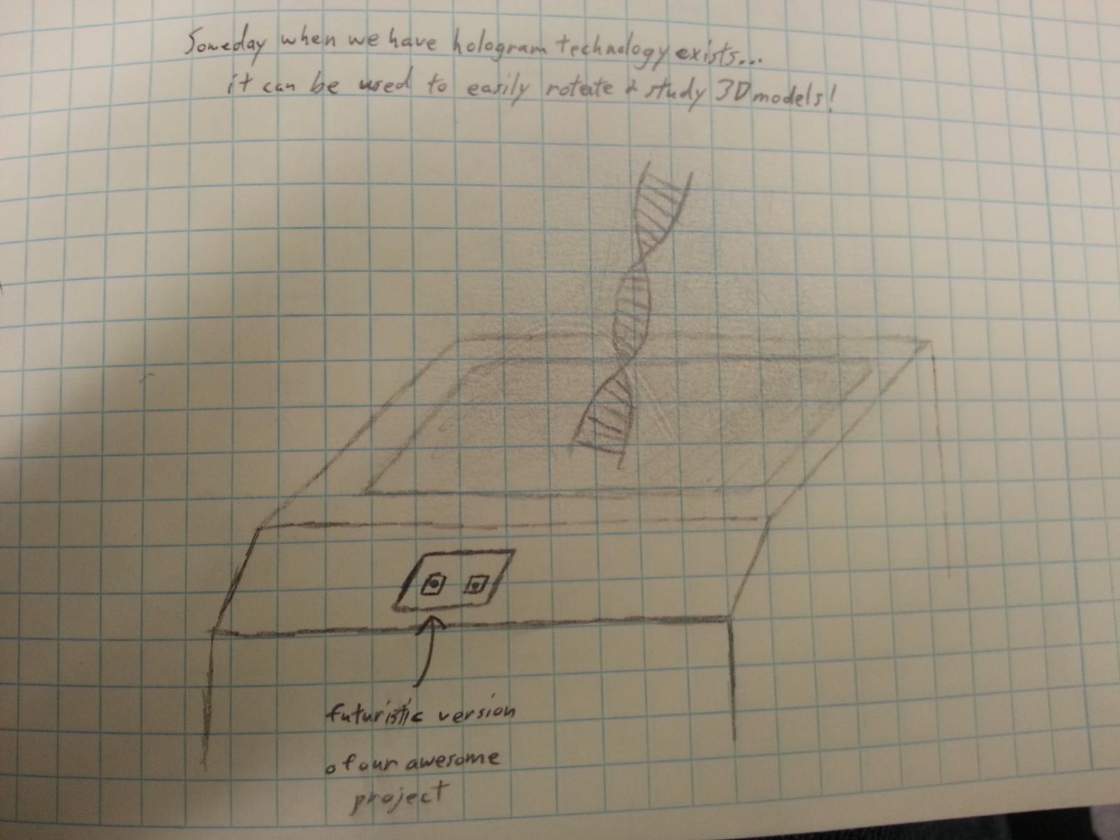
Can be used for educational purposes. For example viewing DNA molecules; the 3D graphics and rotating manipulation allows 360 degrees of examination and studying.
To build the 3d Viewer, we used two potentiometers with the arduino and fed values to processing. We brought 5V and ground to a breadboard from the arduino, and fed those values to each potentiometer. The potentiometers were wired the same – we put 5V on the pin on side ‘3’ of the potentiometer, wired an analog pin from the ardiuno to the middle pin of each potentiometer (using analog pins 0 for one and 1 for the other), and wired the ground to the ‘1’ side of each pot. In all we used — jumper cables between the breadboard and arduino. When we turn the pot, the analog inputs change on the arduino. The potentiometers each had full values of 10k Ohms. To summarize the code, we fetched values from the analog inputs and then converted these values (stored initially as integers) to bytes, and sent them to processing through our ardiuno and computer using a usb cord. Processing then scaled the value of each pin to a number between 0 and 2pi, and these values determined the rotation of the 3d object. We chose to rotate the object about the y and z axes, and both can be done at the same time. This provides the user with the ability to view every part of the 3d object, and rotate it to preferred positions.
Source Code:
//ARDUINO CODE
<pre>
/* FSR simple testing sketch.
Connect one end of FSR to power, the other end to Analog 0.
Then connect one end of a 10K resistor from Analog 0 to ground
For more information see www.ladyada.net/learn/sensors/fsr.html */
int fsrPin = 0;
int fsrReading;
int scndPin = 1;
int scndReading;
byte fsrByte;
byte scndByte;
// the FSR and 10K pulldown are connected to a0
// the analog reading from the FSR resistor divider
void setup() {
// We’ll send debugging information via the Serial monitor
Team Chewbacca: (Group 14)
Karena Cai
Stephen Cognetta
Jean Choi
Eugene Lee
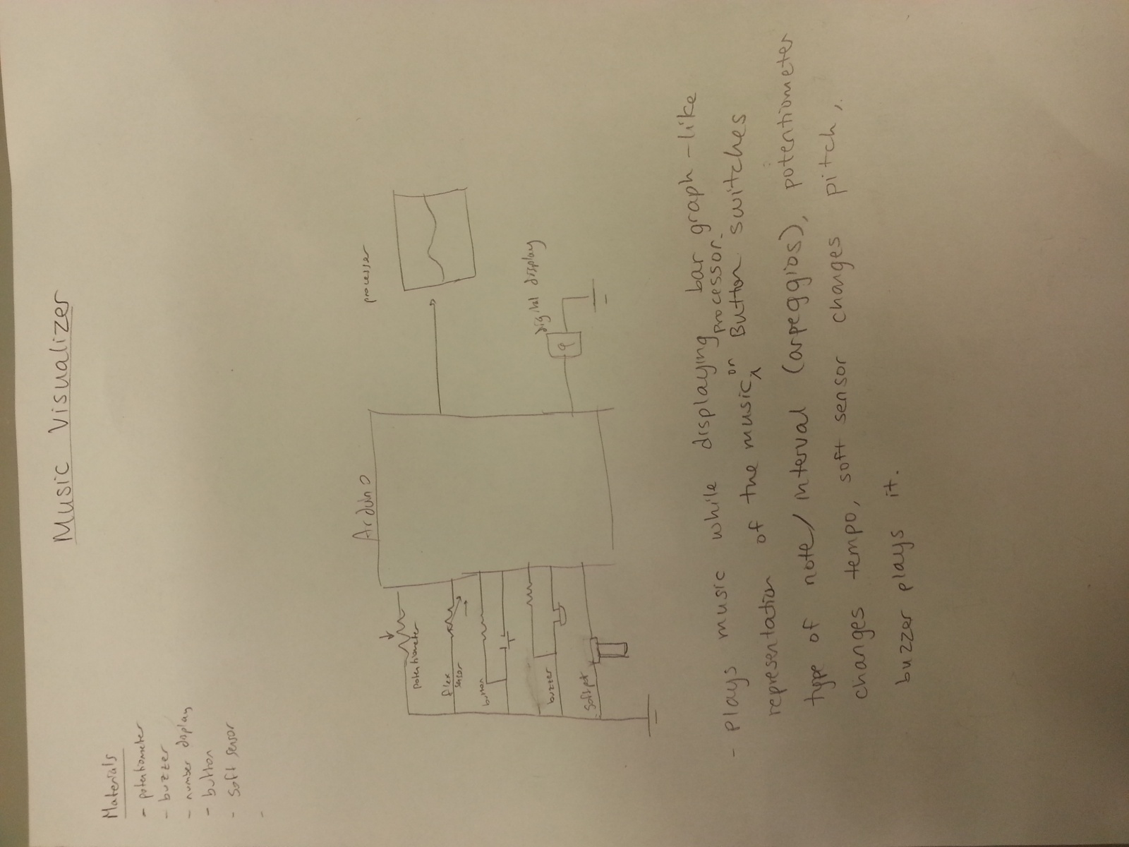
We built a music-visualizer device, where you can play music and visualize the music being played. Using the soft pot sensor to determine pitch, the button to change arpeggio modes, and the potentiometer changes tempo. We used the buzzer to output the sound and Processing to visualize the outputs. We built it because it’s cool, we wanted to integrate Processing with our device, we wanted to do a music project, and we thought it might be useful for helping people who can’t read music to visualize basic music notes and chords in an intuitive way. Overall, this was a successful project in that we were able to visualize the music we played accurately. We didn’t quite get perfect measurements, the soft pot sensor did not seem to exhibit linear behavior. Another issue we had was that we originally attempted to make a different idea, which just played music and changed between tracks: after completing this we ultimately decided to switch to our current idea.
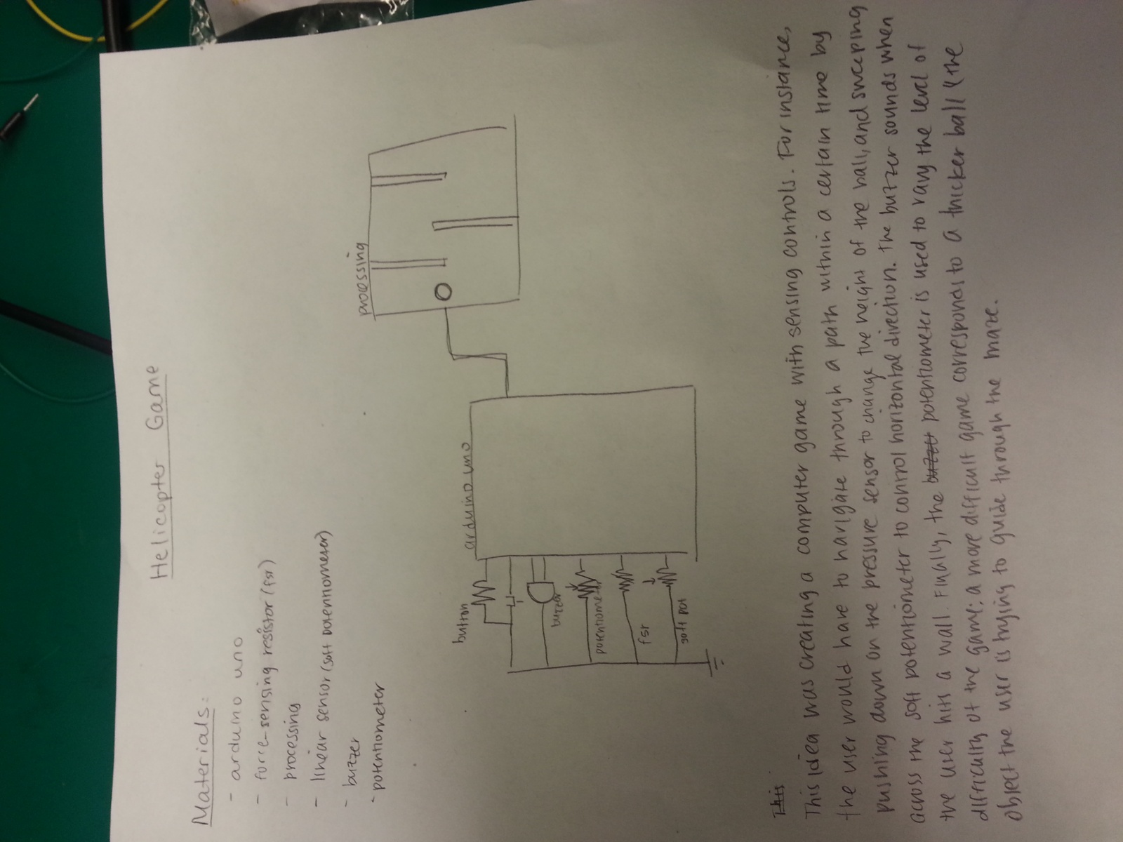
Three Sketches:
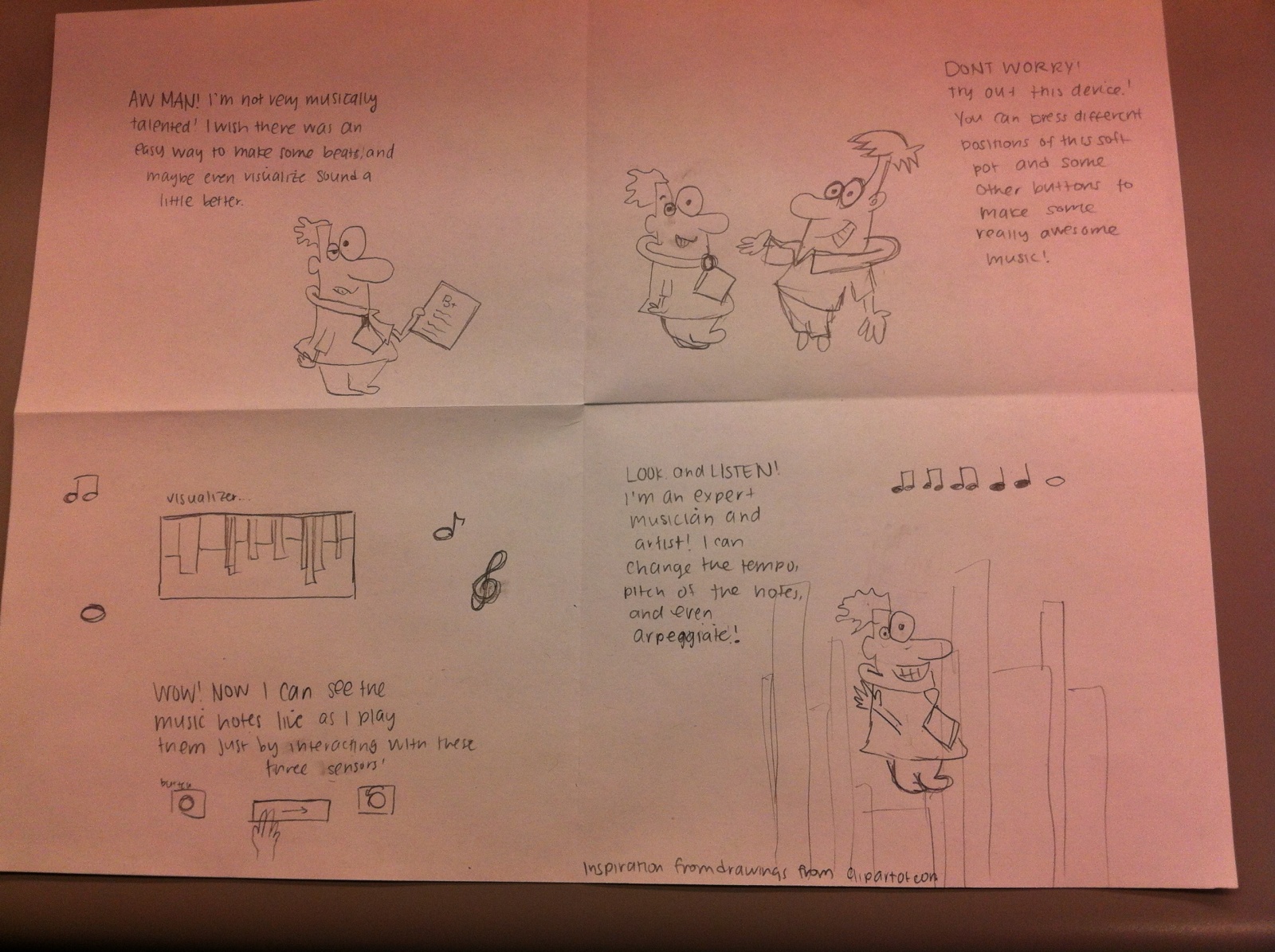
Storyboard:
Video
Materials: Potentiometer
Buzzer
Soft Pot Sensor
Button
Instructions:
– Hook up the inputs: potentiometer, the soft pot, button
– Hook up the outputs: buzzer
– After hooking up those inputs/outputs through the appropriate means, develop the Arduino and Processing code to take the three inputs and output them to the buzzer and to Processing. The detailed circuit diagram is shown above, following that diagram should be sufficient to recreate our design.
Borrowed code/instructions from:
http://www.arduino.cc/en/Tutorial/Graph (Arduino -> Processing code) by David A. Mellis modified by Tom Igoe and Scott Fitzgerald
Source code
Processing Visualizer:
    // Graphing sketch

   // This program takes ASCII-encoded strings
   // from the serial port at 9600 baud and graphs them. It expects values in the
   // range 0 to 1023, followed by a newline, or newline and carriage return

   // Created 20 Apr 2005
   // Updated 18 Jan 2008
   // by Tom Igoe
   // This example code is in the public domain.

   import processing.serial.*;

   Serial myPort;        // The serial port
   int xPos = 1;         // horizontal position of the graph

   void setup () {
     // set the window size:
     size(1000, 300);

     // List all the available serial ports
     println(Serial.list());
     // I know that the first port in the serial list on my mac
     // is always my  Arduino, so I open Serial.list()[0].
     // Open whatever port is the one you're using.
     myPort = new Serial(this, Serial.list()[0], 9600);
     // don't generate a serialEvent() unless you get a newline character:
     myPort.bufferUntil('\n');
     // set inital background:
     background(0);
   }
   void draw () {
   // everything happens in the serialEvent()
   }

   void serialEvent (Serial myPort) {
     // get the ASCII string:
     String inString = myPort.readStringUntil('\n');
     // 0 = lin/frequency, 1 = pot/tempo

     String[] inStrings = split(inString, ',');
     float[] inBytes = new float[inStrings.length];
     println(inString);
     for (int i = 0 ; i < inStrings.length; i++) {          inStrings[i] = trim(inStrings[i]);          inBytes[i] = float(inStrings[i]);      }      //println(inBytes);            inBytes[0] = map(inBytes[0], 0, 1023, 0, width/3);      float tempo = inBytes[0];      inBytes[1] = map(inBytes[1], 0, 1023, 0, height/2);      float frequency = inBytes[1];            float rectWidth = tempo;            // at the edge of the screen, go back to the beginning:      if (xPos + rectWidth >= width) {
       xPos = 0;
       background(0);
     }

     //println(rectangleWidth);
     // draw the line:
     int color1 = color(127, 34, 255 - frequency);
     fill(color1);
     rect(xPos, 0, rectWidth, (int)frequency);

     // increment the horizontal position:
     xPos += rectWidth;
   } // END serialEvent
Arduino
/*
  Graph

 A simple example of communication from the Arduino board to the computer:
 the value of analog input 0 is sent out the serial port.  We call this "serial"
 communication because the connection appears to both the Arduino and the
 computer as a serial port, even though it may actually use
 a USB cable. Bytes are sent one after another (serially) from the Arduino
 to the computer.

 You can use the Arduino serial monitor to view the sent data, or it can
 be read by Processing, PD, Max/MSP, or any other program capable of reading
 data from a serial port.  The Processing code below graphs the data received
 so you can see the value of the analog input changing over time.

 The circuit:
 Any analog input sensor is attached to analog in pin 0.

 created 2006
 by David A. Mellis
 modified 9 Apr 2012
 by Tom Igoe and Scott Fitzgerald

 This example code is in the public domain.

 http://www.arduino.cc/en/Tutorial/Graph
 */

// ******************************************************
// CHORD INITIALIZATION
// ******************************************************
int singleNote[] = { 1, 1, 1, 1 };
int majorChord[] = { 4, 5, 6, 0 };
int minorChord[] = { 10, 12, 15, 0 };
int seventhChord[] = { 20, 25, 30, 36 };
int majorChordLength = 3;
int *chords[] = { singleNote, majorChord, minorChord, seventhChord };
const int chordsLength = 4;

int chordType = 0;                // changes between chords[]
int arpStep = 0;                  // changes between chord frequencies

// ******************************************************
// INPUT INITIALIZATION
// ******************************************************
const int linPin = A0;
const int potPin = A2;
const int btnPin = 12;
const int tonePin = 10;
boolean firstButtonCycle = false; // button 'debouncer'

// pressing the button changes the chord number
void buttonControl(int btnReading) {
  if(btnReading == HIGH){
    // firstButtonCycle prevents the device from changing songs rapidly when
    // the button is held down
    if (firstButtonCycle == false) {
      firstButtonCycle = true;
        // change the chord type
        chordType = chordType < chordsLength - 1 ? chordType + 1 : 0;
      }
  }
  if(btnReading == LOW){
     firstButtonCycle = false;
  }
}

// ******************************************************
// MAIN LOOP
// ******************************************************

unsigned int tempo;
unsigned int frequency;
unsigned int chordFrequency;

void setup() {
  // initialize the serial communication:
  Serial.begin(9600);
}

void loop() {
  int linReading = analogRead(linPin);
  // send the value of analog input 0:
  int potReading = analogRead(potPin);
  int btnReading = digitalRead(btnPin);
  // send the value of analog input 0:

  // wait a bit for the analog-to-digital converter
  // to stabilize after the last reading:
  delay(2);

  tempo = potReading/3 + 10;

  buttonControl(btnReading);
  int* chord = chords[chordType];
  float chordFactor = (float)chord[arpStep] / (float)chord[0];

  if (linReading < 1020) {
    frequency = linReading;
  }
  chordFrequency = frequency * chordFactor;

  Serial.print(tempo);
  Serial.print(",");
  Serial.println(chordFrequency);
//Serial.print(",");
//  Serial.println(chordType);

  unsigned int duration = tempo - tempo / 20;
  delay(tempo);
  tone(tonePin, chordFrequency, duration);
  arpStep = arpStep < majorChordLength ? arpStep + 1 : 0;
}
We built a quite advanced drumkit with the force-sensing resistor. By toggling the input mode on an input button, the user changes the drum instrument sample. Then, he/she taps a drumbeat into the FSR. The drumbeat is recorded into processing and other samples can be recorded by cycling through samples with the input button. At the end, the final mode allows the user to play back all the recordings in unison, using Processing and our computer speakers. We chose this project because all of us are musically inclined; Shubhro is a musician, both David and Miles are singers, and Andrew is a dancer! Altogether, making a drum machine is really fun and awesome. The end product turned out to be a great success! We had some technical challenges, but at the end we pulled through. In the final result, we like that the machine manages to overlay recordings from different sound samples. Among the things that didn’t work, Processing wouldn’t play all the sounds we wanted it to on the Arch Linux machines. Everything worked OK on Shubhro’s Mac, though. Also, delays in sound playback were a difficult annoyance.
In these schematics, we’ve drawn the wiring for our drum kit, strength tester, and morning room lighter, respectively.
In this storyboard, we see a user previously fed up with music product software celebrate the ease-of-use in our drumkit.
Video of System in Action
Parts Used
Arduino
Button sensor
Two 330-ohm resistors
Force-sensitive resistor
Potentiometer
Various wires
Assembly Instructions
To a breadboard, attach a force-sensing resistor (FSR) in series with one of the 330-ohm resistors in the pull-down configuration. Also attach the potentiometer in series with the other resistor, also in the pull-down configuration.
Connect the second pin of the potentiometer to pin A2 in the Arduino.
Connect pin A0 on the Arduino in between the FSR and the 330-ohm resistor.
Attach the button to pin 2, the voltage source and ground from the Arduino.
Source Code
import processing.serial.*;
import cc.arduino.*;
import ddf.minim.*;

/*Drumkit for Princeton COS436 - HCI Lab 1.  David Dohan*/

Arduino arduino;
Minim minim;


/*Pins*/
//Analog in
int drumFsr = 0;
int volumePot = 2;
//Digital in
int modeButton = 2;
//Digital out
int beeper = 3;

/*Beat information*/
int numTracks = 10; //Number of tracks
int cTrack = 0;
int trackSize = 10000; // Most possible ticks
int lastBeat = 0;      // Last current tick before looping
int[][] tracks = new int[numTracks][]; //All the tracks
AudioPlayer[] sounds = new AudioPlayer[numTracks]; //Sounds to play for each track
String[] names = {"kick", "tss", "cymbal"};

/*state*/
int numStates = 5; //0,1 record/hold
int state = 1; //0:play 1:hold 2-4:record drum types
int beat = 0;
int cutoff = 20;
double delayms = 1;
int lHit = 0;


void setup()
{
    println("Serial ports: ");
    println(Serial.list());
    arduino = new Arduino(this, Arduino.list()[6],57600);
    arduino.pinMode(drumFsr, Arduino.INPUT);
    arduino.pinMode(volumePot, Arduino.INPUT);
    arduino.pinMode(modeButton, Arduino.INPUT);
    clearTracks(); //Initialize tracks

    minim = new Minim(this);

    //Load sounds
    sounds[0] = minim.loadFile("drums/kick.mp3");
    sounds[1] = minim.loadFile("drums/snare.mp3");
    sounds[2] = minim.loadFile("drums/cymbal.mp3");
    sounds[2].setGain(-10);
}

void cleanTracks() {


}

void nextState() {
    beat = 0;
    state = (state + 1) % numStates;
    if (state == 1) {
        lastBeat = 0;
        clearTracks();
    } else if (state == 0) {
      cleanTracks();
    } else {
       println(names[state-2]);
    }
}

void clearTracks() {
    for (int i = 0; i  cutoff && lHit < cutoff) {
      tracks[cTrack][beat] = hit;
  }
    //println(hit);
      beat -= 1;
      play();
      beat += 1;
    if (state == 2) { lastBeat = max(beat,lastBeat); }
    lHit = hit;
}

void play() {
    //Cheap edge case avoidance...
    if (beat <= 0 || beat == trackSize - 1) { return; }
    for (int t = 0; t  0 && tracks[t][beat] > tracks[t][beat-1] &&
        //tracks[t][beat] > tracks[t][beat + 1]) {
        if (tracks[t][beat] > 0) {
            //print("Play");
            //println(t);
            sounds[t].play(0);
        }
    }
}

void draw()
{
    /*
     * Check button - mode change?
     * If play, then play current tick. Advance.  Read potentiometer to get tempo
     * If hold, do nothing
     * If record, then record fsr to current track/tick.  Play other tracks as
     *      well.
     */

    if (arduino.digitalRead(modeButton) == arduino.HIGH) {
        //Manage debounce
        while (arduino.digitalRead(modeButton) == arduino.HIGH) { print("") ; }
        nextState();
        print("Debounced: ");
        println(state);
    } else {

        switch (state) {
            case 0:
                play();
                break;
            case 1:
                hold();
                break;
            default:
                record();
                break;
        }
    }
    beat = (beat + 1) % trackSize;
    delay(arduino.analogRead(volumePot));
}
Members:
Clay Whetung (cwhetung@)
Jae Young Lee (jyltwo@)
Jeff Snyder (jasnyder@)
Michael Newman (menewman@)
What we built:
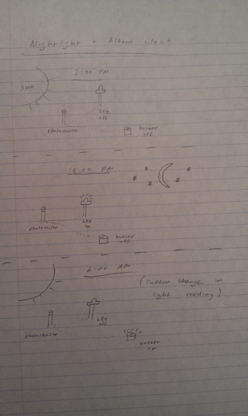
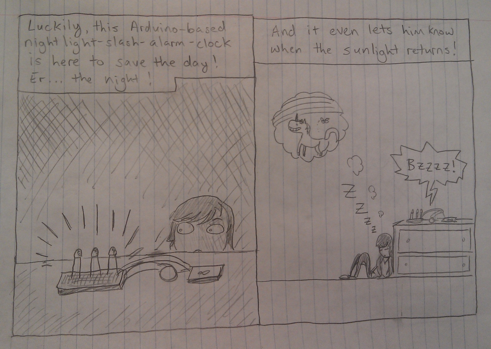
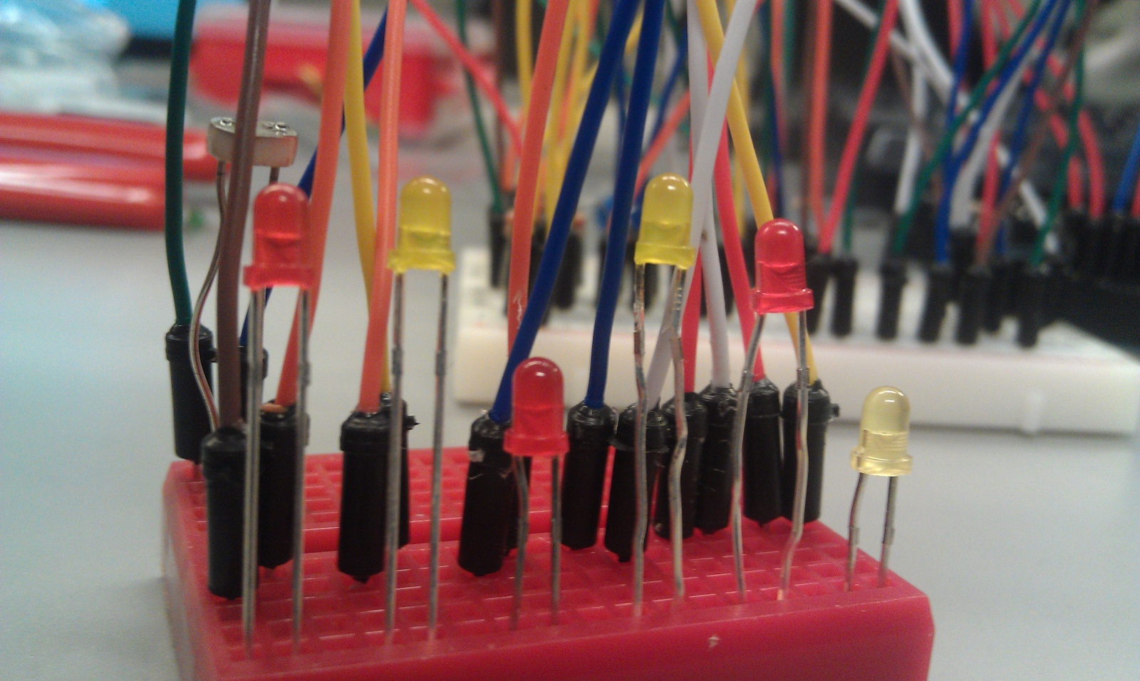
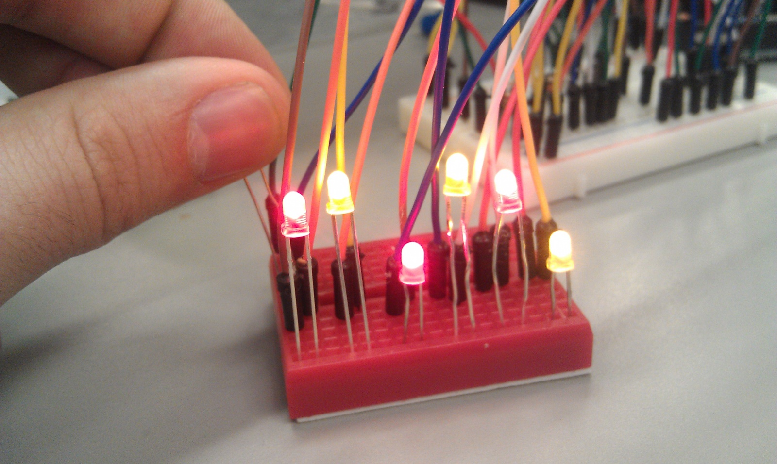
We chose to build a nightlight combined with a wake-up alarm. Our nightlight features not one, not two, not three, not four, not five, but SIX — yes, SIX! — LEDs that turn on when a photosensor detects a decreased amount of ambient light. Not only that, but we also included a buzzer that plays a friendly tune whenever our system detects that ambient light levels have increased again. The purpose of this system is twofold: First, by providing light when its surroundings are dark, it reassures and comforts those who are afraid of the dark. Second, it audibly announces the return of light to those who might have closed their eyes or otherwise lost sensory input (e.g., the sleeping or suddenly blind). Our system is a smashing success, as it correctly lights up in the dark and plays a tune, as specified. We particularly liked the reassuring charm of the system’s adorable lights and catchy jingle. A possible improvement would be implementing a continuous alarm that the user can turn off (for example, by turning a potentiometer) — more like a typical alarm clock. We could even include a snooze button.
Design sketches:
Arduino Orchestra Instrument: Pitch is controlled with soft pot, and volume is controlled with FSR.
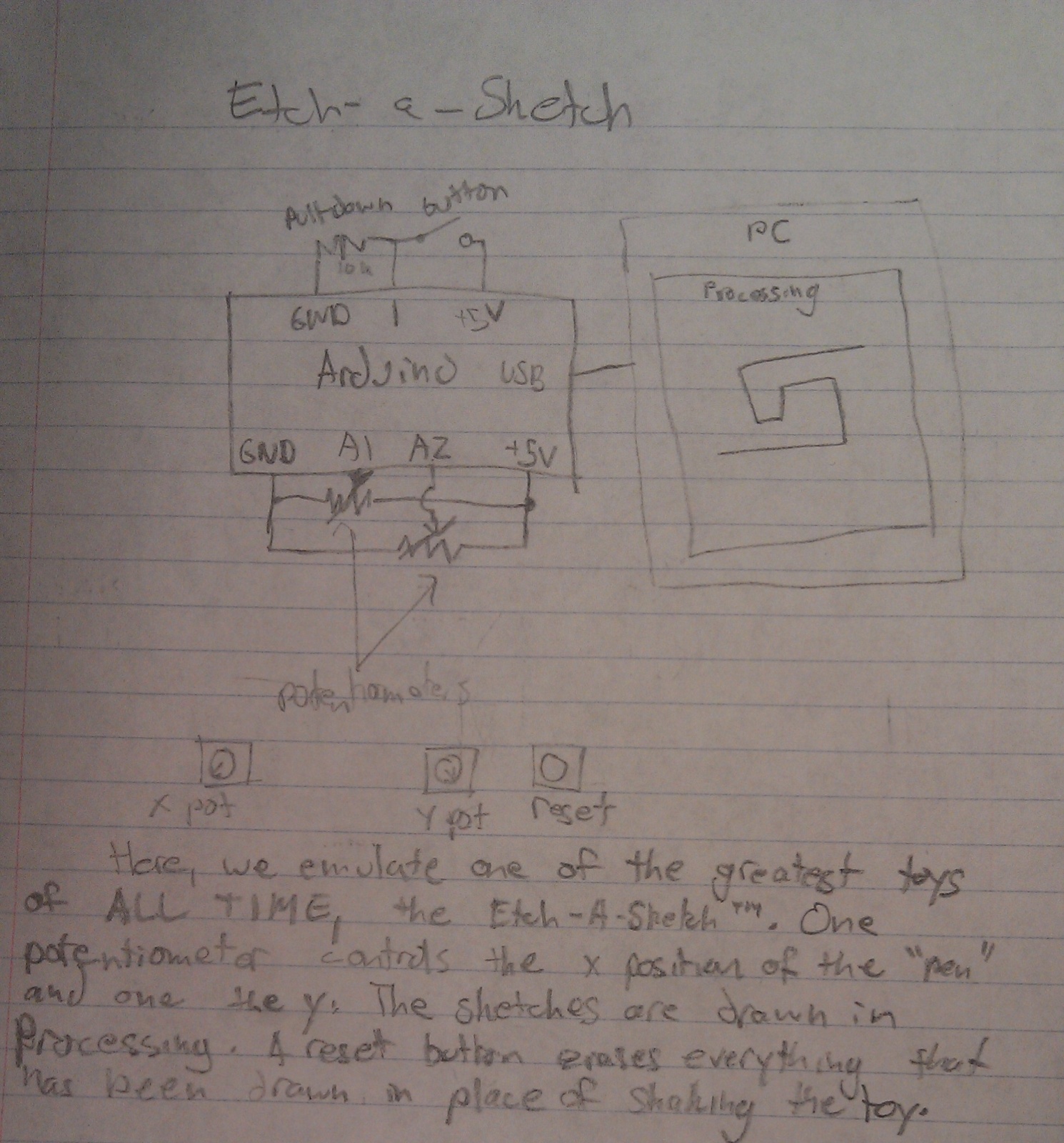
Etch-a-Sketch: Potentiometers control the x and y coordinates of the “pen,” and a drawing is rendered onscreen using Processing.
Nightlight/Alarm Clock: LEDs turn on when the light dims, and buzzer goes off when light is restored.
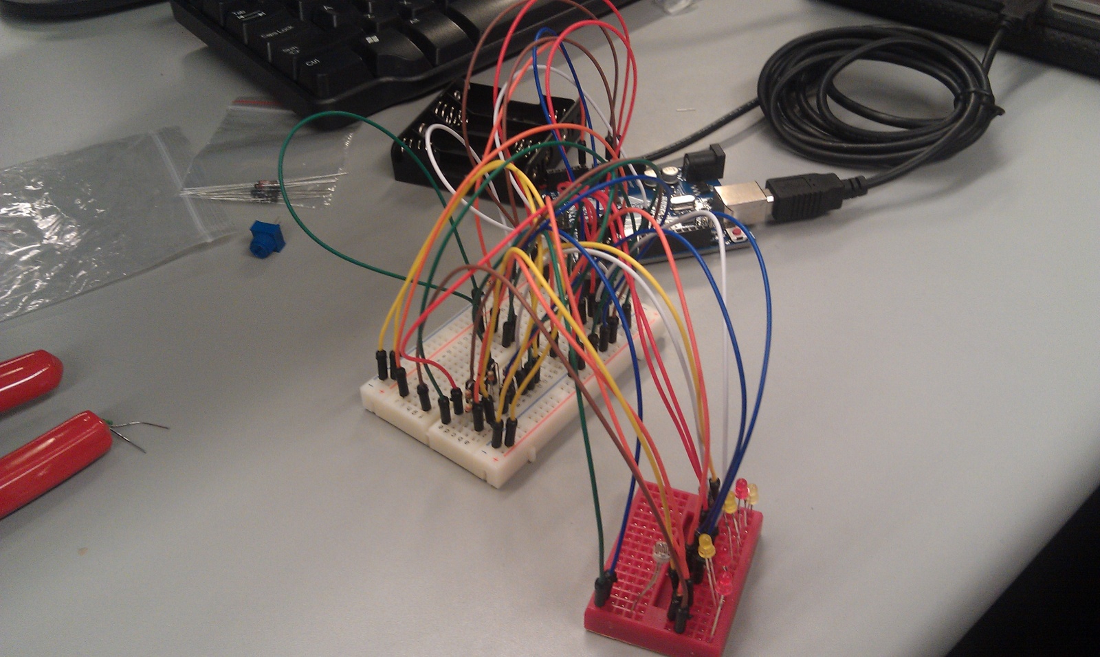
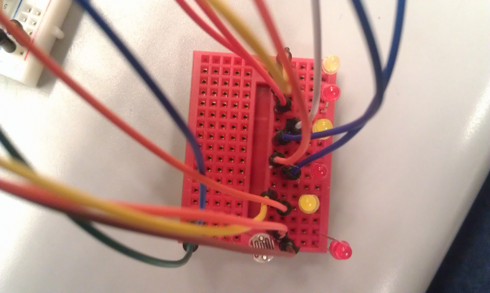
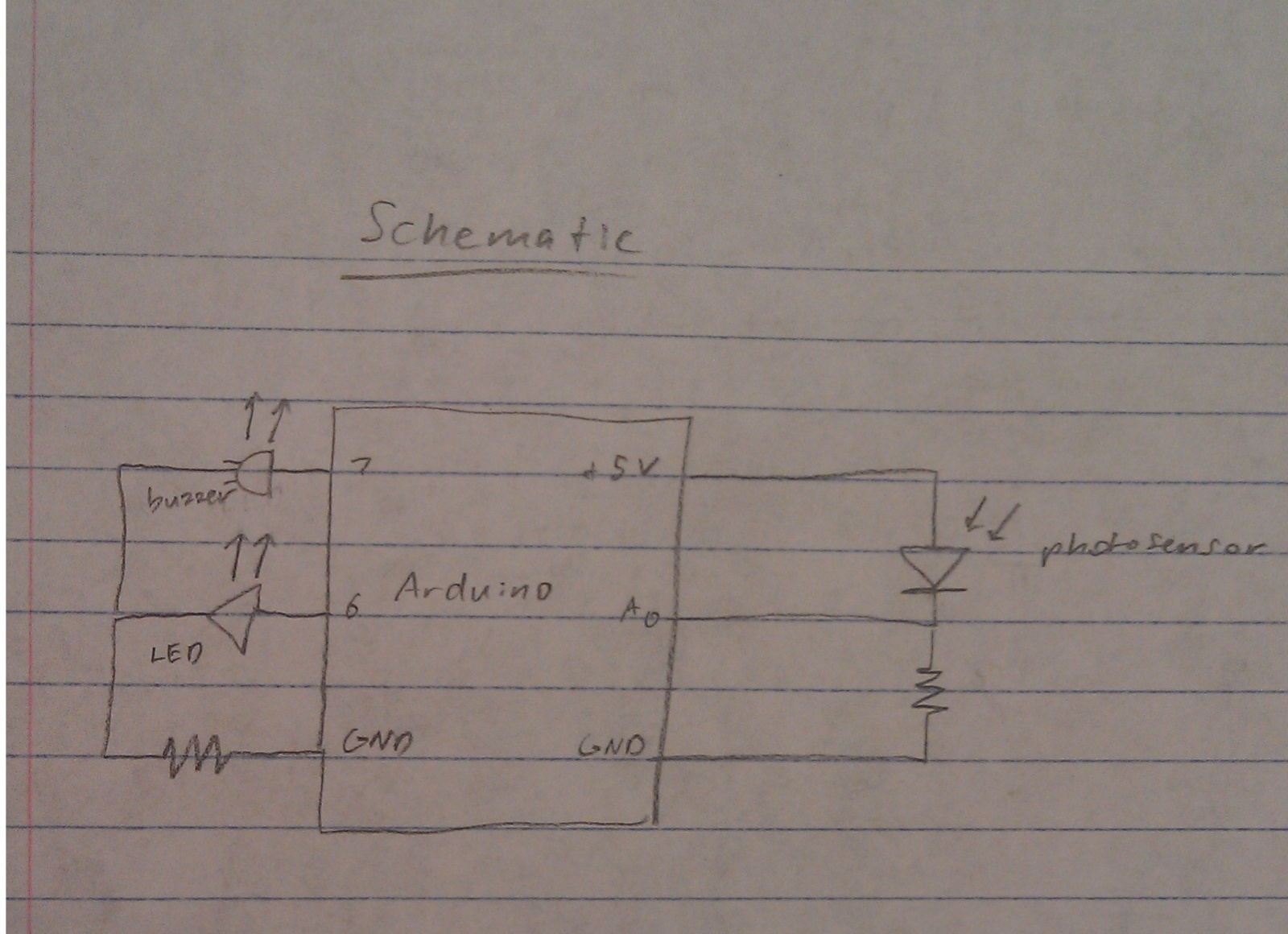
1. Set up the LEDs in a line on a breadboard next to the photoresistor. Place the speaker across the center divider of the other breadboard. You may find it helpful to connect ground and +5V to the power rails of the breadboard for the following steps.
2. Make the following connections:
– Connect the anodes of the 6 leds to pins 0-5 of the arduino.
– Connect the cathode of each LED to ground via a 330 ohm resistor.
– Connect one pin of the speaker to pin 8 and the other to ground via a 330 ohm resistor.
– Connect one side of the photoresistor to a +5V pin.
– Connect the other side both to A0 and to ground via a 10 kilo-ohm resistor.
3. Check the values output by the photoresistor using the serial monitor and the Serial.println() function. In the code, change the PHOTO_MAX and PHOTO_MIN values as appropriate.
4. Enjoy the comfort and security of living with the sweet alarm nightlight.
Source Code:
/*
  Authors: jasnyder, cwhetung, menewman, jyltwo
  Date: 2/25/2013
  COS 436 Lab L1: The Nightlight Alarm

  The nightlight alarm: lights turn on when it's dark, and when it
  gets bright again, the lights turn off and an alarm goes off to
  wake you up!
*/

#include "pitches.h"

const int FALSE = 0;
const int TRUE = 1;

//  Input / Output Constants
const int PHOTO_MIN = 100;  // set me as appropriate!
const int PHOTO_MAX = 1023;  // set me as appropriate!
const int DARKNESS = 500;  // set me as appropriate!
const int LIGHT = 700;  // set me as appropriate!

//  Musical Constants
const int NOTE_DELAY = 300; // (ms)
const int NOTE_DUR = 250;

//  Pin Connection Constants
const int photo = A0;
const int red1 = 5;
const int red2 = 3;
const int red3 = 1;
const int yellow1 = 4;
const int yellow2 = 2;
const int yellow3 = 0;
const int speaker = 8;

//  Variables
boolean islight = false;
int photovalue = 0;  //  value returned by photo sensor

//  Set internal pull-ups for output on LED pins
void setup()
{
  pinMode(red1, OUTPUT);
  pinMode(red2, OUTPUT);
  pinMode(red3, OUTPUT);
  pinMode(yellow1, OUTPUT);
  pinMode(yellow2, OUTPUT);
  pinMode(yellow3, OUTPUT);
}

void loop() {
  //  Grab the light value
  photovalue = analogRead(photo);

  // If it has recently become dark, turn on nightlight
  if (photovalue < DARKNESS && islight) {
    digitalWrite(0, HIGH);
    digitalWrite(1, HIGH);
    digitalWrite(2, HIGH);
    digitalWrite(3, HIGH);
    digitalWrite(4, HIGH);
    digitalWrite(5, HIGH);
    islight = false;
  }
  // If it has recently become light, turn off nightlight and play alarm
  else if (photovalue > LIGHT && !islight) {
    digitalWrite(0, LOW);
    digitalWrite(1, LOW);
    digitalWrite(2, LOW);
    digitalWrite(3, LOW);
    digitalWrite(4, LOW);
    digitalWrite(5, LOW);
    playAMerryWakingUpSong();
    islight = true;
  }
}

//  Play a classic little ditty!
void playAMerryWakingUpSong() {
  tone(speaker, NOTE_C5, NOTE_DUR);
  delay(NOTE_DELAY);
  tone(speaker, NOTE_C5, NOTE_DUR);
  delay(NOTE_DELAY);
  tone(speaker, NOTE_AS4, NOTE_DUR);
  delay(NOTE_DELAY);
  tone(speaker, NOTE_C5, NOTE_DUR*.75);
  delay(NOTE_DELAY*2);
  tone(speaker, NOTE_G4, NOTE_DUR*1.5);
  delay(NOTE_DELAY*2);
  tone(speaker, NOTE_G4, NOTE_DUR);
  delay(NOTE_DELAY);
  tone(speaker, NOTE_C5, NOTE_DUR);
  delay(NOTE_DELAY);
  tone(speaker, NOTE_F5, NOTE_DUR);
  delay(NOTE_DELAY);
  tone(speaker, NOTE_E5, NOTE_DUR);
  delay(NOTE_DELAY);
  tone(speaker, NOTE_C5, NOTE_DUR);
  delay(NOTE_DELAY);
}
Connie Wan (cwan), Angela Dai (adai), Kiran Vodrahalli (knv), Edward Zhang (edwardz)
Group 13 (aka CAKE)
We built a pseudo Etch-A-Sketch emulator that modifies its appearance based on the user’s environment – the temperature and light conditions. Instead of only drawing horizontal and vertical lines, we can draw curved lines by changing the slope of the current line to be drawn. We use two potentiometers to serve as the knobs of this “Curve-A-Sketch” and use Processing to display the user’s drawing. The ambient light level controls the color of the drawing, while the temperature controls the width of the stroke. This project was a lot of fun to play with because of the nostalgia of playing with a childhood toy, enhanced with the novel control of changing its color and stroke width – for example, we could change colors simply by touching the temperature sensor, and width by moving our head over the photoresistor. We also wanted to blow on the temperature sensor to change color, but it didn’t quite work out because of some bugs with a clear button. The clear button only worked sometimes, because the circuit was a bit buggy– quick changes in resistance messed up the data we sent from the Arduino to processing.
Sketches
Ambient Etch-A-Sketch: Remember the Etch-a-Sketch? This lets you do everything the Etch-a-Sketch did, and more! The features of your cursor , such as color and pen width, change based on your ambient environment conditions (temperature and light).
The upper half of this image shows an LED light array that lights up in concert with the location of your finger. With an added control for color, you can create a mini light show using just your hands. The lower half shows our Smart Nightlight. As its basic function, the tricolor LED will be brighter if the room is darker (we put a screen between the LED and the photoresistor to eliminate feedback). The user can change the color and the overall brightness of the nightlight.
Storyboard
Ambient Etch-A-Sketch Storyboard
Final System
This video demonstrates the features of our Ambient Etch-a-Sketch. It shows the user controlling the color and pen width with the photoresistor and thermistor, respectively.
List of parts
2x Potentiometer (rotary)
1x Arduino Uno
1x Push Button
1x Photoresistor
1x Thermistor
3x 10KΩ Resistor
1x Breadboard
Wires
Computer
Instructions
Plug the two potentiometers into opposite sides of the breadboard. Fix an orientation – the one on the left controls the horizontal coordinate, and the one on the right controls the vertical coordinate. Attach the middle pin of the right potentiometer to A0 and the middle pin of the left potentiometer to A1. Attach the side pins of both potentiometers to 5V and ground.
Connect one side of the thermistor to 5V, and the other side to A2 and ground through a 10KΩ pull-down resistor.
Connect one side of the photoresistor to 5V, and the other side to A2 and ground through a 10KΩ pull-down resistor.
Connect one side of the push button through a 10KΩ resistor to 5V and the other side to D2 and ground.
Run the Arduino code, and then start the Processing application
Draw! The extreme settings of the knobs correspond to the sides of the Processing window. You can adjust the color by shadowing the photoresistor (e.g. leaning over so your head blocks some light), and change the stroke width by changing the temperature (the easiest way is by pressing the thermistor between your fingers).
Source Code
Arduino Code
/*
 Ambient Etch-a-Sketch!
 Lab 1
 COS 436: Human-Computer Interfaces
 February 20, 2013

 */

//variables
int y; //y coordinate of etch-a-sketch
int x; //x coordinate of etch-a-sketch
int temperature; //temperature of the room
int light; //light ambience of the room
int clearButton; //clear Button

//pins
int pinY = 0;
int pinX = 1;
int pinTemperature = A2;
int pinLight = 3;
int pinClearButton = 7;

void setup()
{
  // initialize the serial communication:
  Serial.begin(9600);

  // initialize the clear button as an input
  pinMode(pinClearButton, INPUT);

}

void loop() {
  // read data on every loop
  x = analogRead(pinX);
  y = analogRead(pinY);
  light = analogRead(pinLight);
  temperature = analogRead(pinTemperature);
  clearButton = digitalRead(pinClearButton);

  //test it works
  //Serial.println("Scaled x: \n");
  if((x < 1024) && (y < 1024) && (light < 1024) && (temperature < 1024) && (clearButton <= 1)) {
    Serial.println(x);
    Serial.println(y);
    Serial.println(light);
    Serial.println(temperature);
    Serial.println(clearButton);
  }
  delay(100);
}
Krithin Sitaram (krithin@)
Amy Zhou (amyzhou@)
Daniel Chyan (dchyan@)
Jonathan Neilan (jneilan@)
Thomas Truongchau (ttruongc@)
Group 11
Expressive Drum Pad
We built a drum pad that can play a range of pitches controlled by a softpot (touch sensitive slide), along with a range of amplitudes controlled by a FSR. The harder a performer strikes the FSR, the louder the buzzer sounds. Sliding towards the right will cause an increase in pitch, while sliding towards the left will cause a decrease in pitch. Combining the two controls, a performer can play a variety of virtuosic pieces that require a single voice. We decided to build the Expressive Drum Pad because we all appreciate music creation and wanted to contribute to the creative musical process. The Expressive Drum Pad turned out nicely as it allows the performer to control pitch and amplitude rather effectively through an intuitive, yet unpolished interface. Future improvements would include having an enclosure to hold down the sensors.
Design 1: An Electronic Birthday Candle
Design 2: A Biometric Flexor Password Device
Design 3: The Expressive Drum Pad
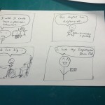
Storyboard for the Expressive Drum Pad
Parts Used
– 1 Arduino
– 1 FSR
– 1 softpot (touch-sensitive slide)
– Buzzer (replaced by computer speakers for additional volume)
[Reid approved this substitution.]
Connect the softpot to 5V, Ground, and an Arduino analog input pin. Connect the buzzer (computer speakers) in series with the FSR as part of the circuit from an Arduino digital output pin to ground. Angle the breadboard such that the softpot and FSR lie flat on a table.
Source Code:
int OUTPUTPIN = 3;
int FSRPIN = 5;
int SOFTPOTPIN = 0;
int MINSOFTPOT = 0;
int MAXSOFTPOT = 1024;
int MINPITCH = 120;
int MAXPITCH = 1500;

void setup() {
pinMode(OUTPUTPIN, OUTPUT);
Serial.begin(9600);

}

void loop() {
int frequency = map(analogRead(SOFTPOTPIN), MINSOFTPOT, MAXSOFTPOT, MINPITCH, MAXPITCH);
tone(OUTPUTPIN, frequency);
delay(2);
Serial.println(analogRead(FSRPIN));
}
1) Names: Philip Oasis, Alice Fuller, Gene Merewether, and Rodrigo Menezes
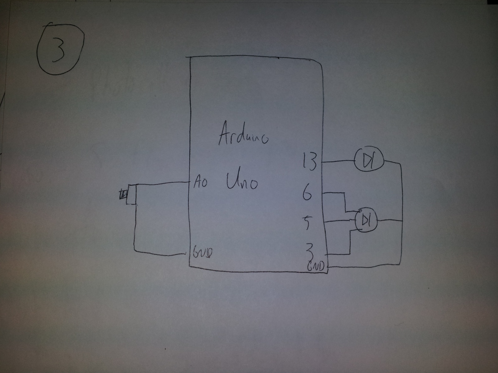
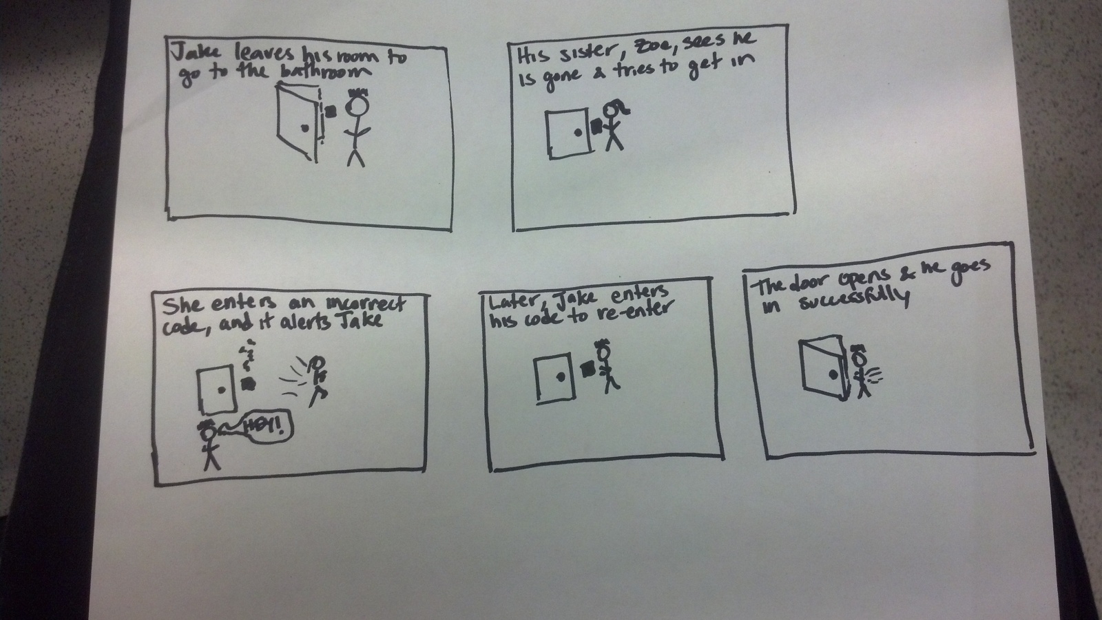
2) Group Number: 6 3) We built a sensor-based authentication system. The idea behind it is that you enter in a code the first time, and then on subsequent uses you have to enter in the same code. We had three sensors: two potentiometers which had to be turned the correct degree and one slide sensor which had to have your finger placed in the correct position. The end result was really great. The correct position, given a small amount of error could be found again, but a knowledge of the initial code was still needed. When you got the code correct a green light went off, and when you got it wrong a buzzer went off. I enjoyed the fact that you had to have your finger in the correct position on the sensor while you pushed the button, the multiple tasks reminds me of cool authentication systems that you see in movies. It might have been nice to have things in a prettier display; we could have obscured the wires better, had the sensors further apart to improve ease of movement, had written instructions. This would have also been much better if there was an actual lock to unlock.
4)
This is a simple reaction game in which the buzzer sounds, the user hits the button as quickly as possible, and the LED then lights up to give them feedback on how quickly they reacted.
This is a memory game in which the user hits buttons to recreate the order the LED’s flashed, and the sequence gets one light longer for each round the user gets correct.
This is a racing reaction game in which the LED flashes red, yellow, and green and then the user tries to hit the button as soon as possible after a green. The buzzer would go off in the event of a false start, and the LED would light up with a color to indicate the reaction time.
Attach these all on one breadboard:
Attach one potentiometer to pin 0 on the arduino, the other to pin 1. Attach the button to pin 2, the buzzer to pin 3, and the led to pin 5. There should be a 330 ohm resistor attached with the led and the buzzer, and a 10k ohm to the button. The two potentiometers should be next to each other at the front, the button should be just behind them, and the buzzer and led are at the back of the breadboard. On the separate smaller breadboard place the slide sensor and connect it to pin 2.
9) Source Code
const int potentialPin1 = 0;
const int potentialPin2 = 1;
const int slidePin = 2;
const int buttonPin = 2;
// pull-down resistor; LOW is not pressed
const int buzzerPin = 3;
const int ledPin = 5;
const int tolerance = 64;
const int buzzerTone = 20;
void loop()
{
int buttonState = digitalRead(buttonPin);
int potentialState1 = analogRead(potentialPin1);
int potentialState2 = analogRead(potentialPin2);
int slideState = analogRead(slidePin);