
Lab 3: Motor Control
Bereket Abraham
Lauren Berdick
Ryan Soussan
Andrew Ferg
Group #24: The Cereal Killers
Z Flipper
We built the Z-Flipper, a robot designed to flip over itself multiple times. It was made out of 3 panels connected by servo motors at the joints. The construction was good, but our servo motors were too weak to lift the entire weight of the robot. The second robot we constructed, the Wormotrom, moved like an inchworm. The robot moved at a slow but steady pace, and put less strain on the motors. However, we were unable to control the direction the robot moved in. In the future, we would remember to consider the strength of our motors during the brainstorming and idea selection process.
12 Robot Ideas
1. 2 servos on either side of a piece of styrofoam and have it crawl along.
2. 2 DC motors attached to wheels on either side of a piece of styrofoam with a passive trailing wheel. A 3 wheel cart. You could turn by spinning one side faster than the other.
3. Put a piece of styrofoam on a 3-wheeled tripod. Attach a DC motor on the back as a fan. Blows across the table.
4. 2 servos attached to a ribbon. The servos turn in opposite directions, causing the ribbon to contract and expand. Much like a worm.
5. One servo with a gripper claw attached. The motor sweeps from 0 to 30 deg slows, and then back quickly. The robot claws it way across the table. Perhaps you would need two trailing legs for stability.
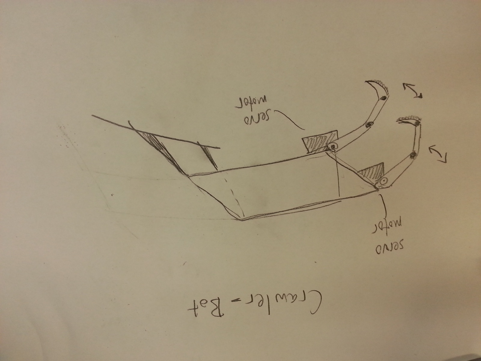
6. The same thing as above except now we have 2 gripper claws on either side. This configuration could also be used to climb as well as crawl.
7. Attach tiny helicopter blades to the DC motor. The robot flies into the air with a burst of speed, then glides over to the other side of the table.
8. Two DC motors attached to wheels and connected by some kind of thick rubber band or track. The motors are fixed together and the track rotates around them, like a really basic tank.
9. Create a hollow cylinder with a DC motor at the central axis. Attached to the motor is a weighted rod, or a pendulum. As the motor turns, it shifts the cylinder’s center of mass, causing it to turn.
10. A four legged robot with a rotating hip. One servo would control the hip and one DC motor would control the front two legs. The back legs would be passive / wheeled. The front legs would be 180 degrees out of phase, so that as the hip turned one leg would be in the air and the other would be pulling the robot forward.
11. The entire path has a track or ladder. The robot simply has a DC motor that pulls itself along the track.
12. Cover the table in a few inches of water. Make a small boat and with 2 paddles connected to servo motors. Or a DC motor connected to a propellor.
13. 3 flat plates in the shape of a “Z”. At each joint is a servo motor. The plates open up, causing the robot to flip over. The robot moves forward by flip over and over in the right direction.
Final Idea: #13
At first, we thought about doing the crawler, #6.
But then we decided on the “Z Flipper”, #13.
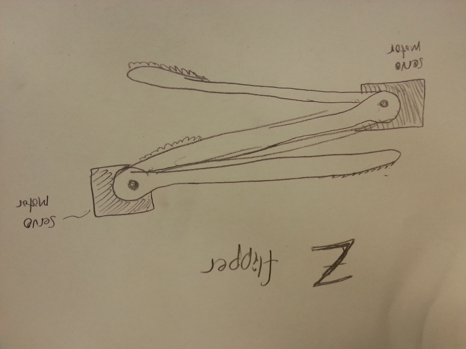
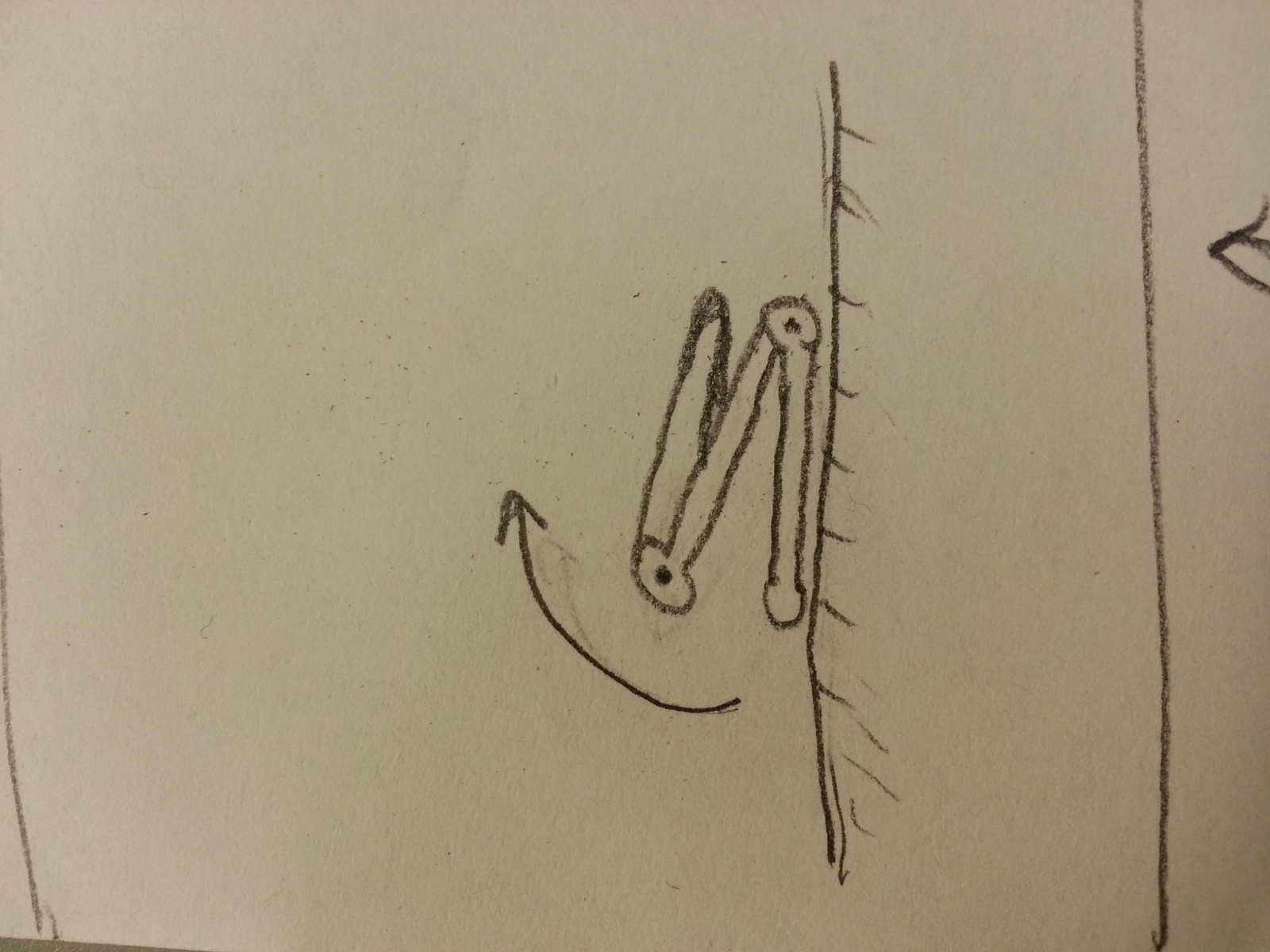
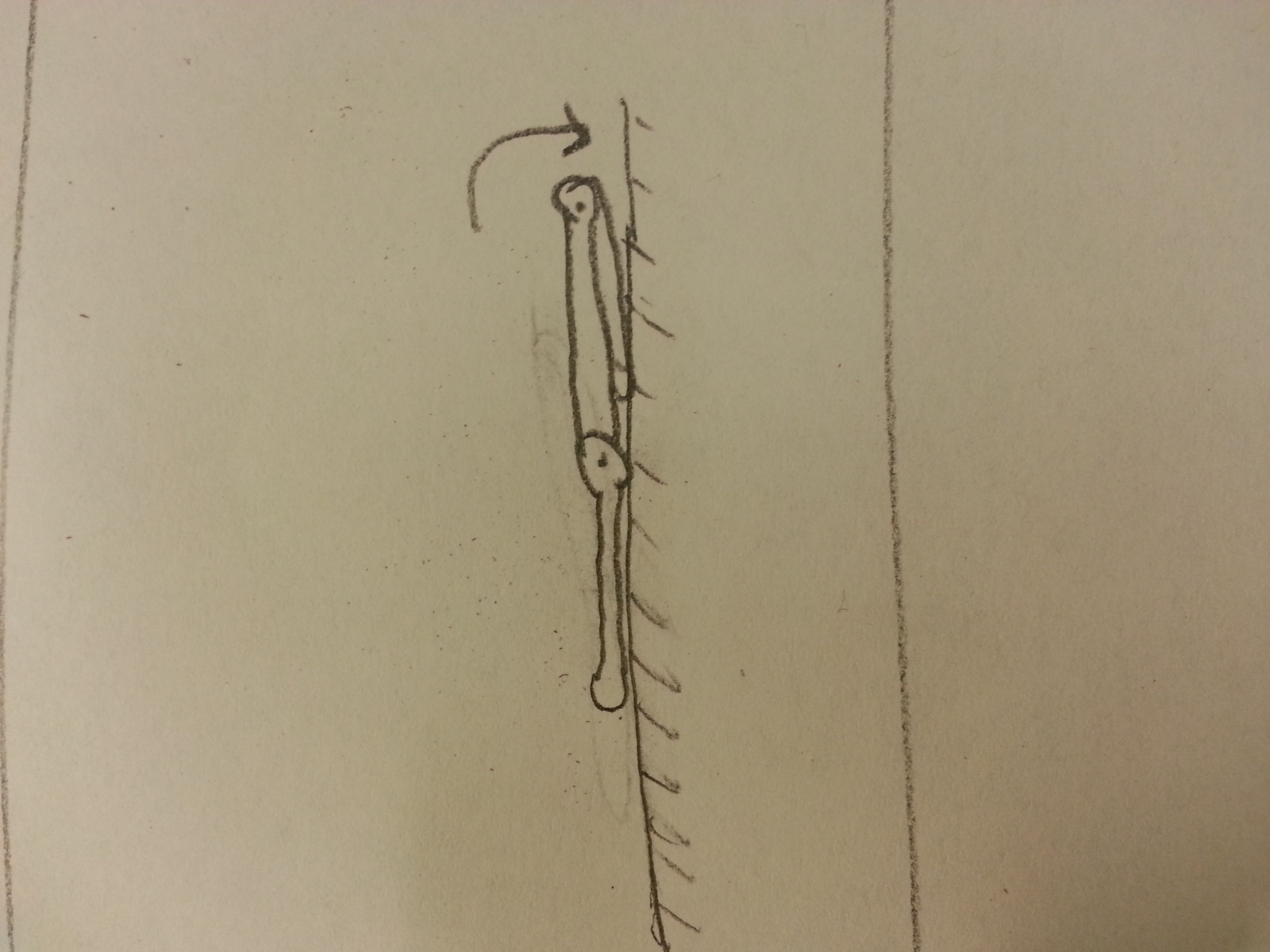
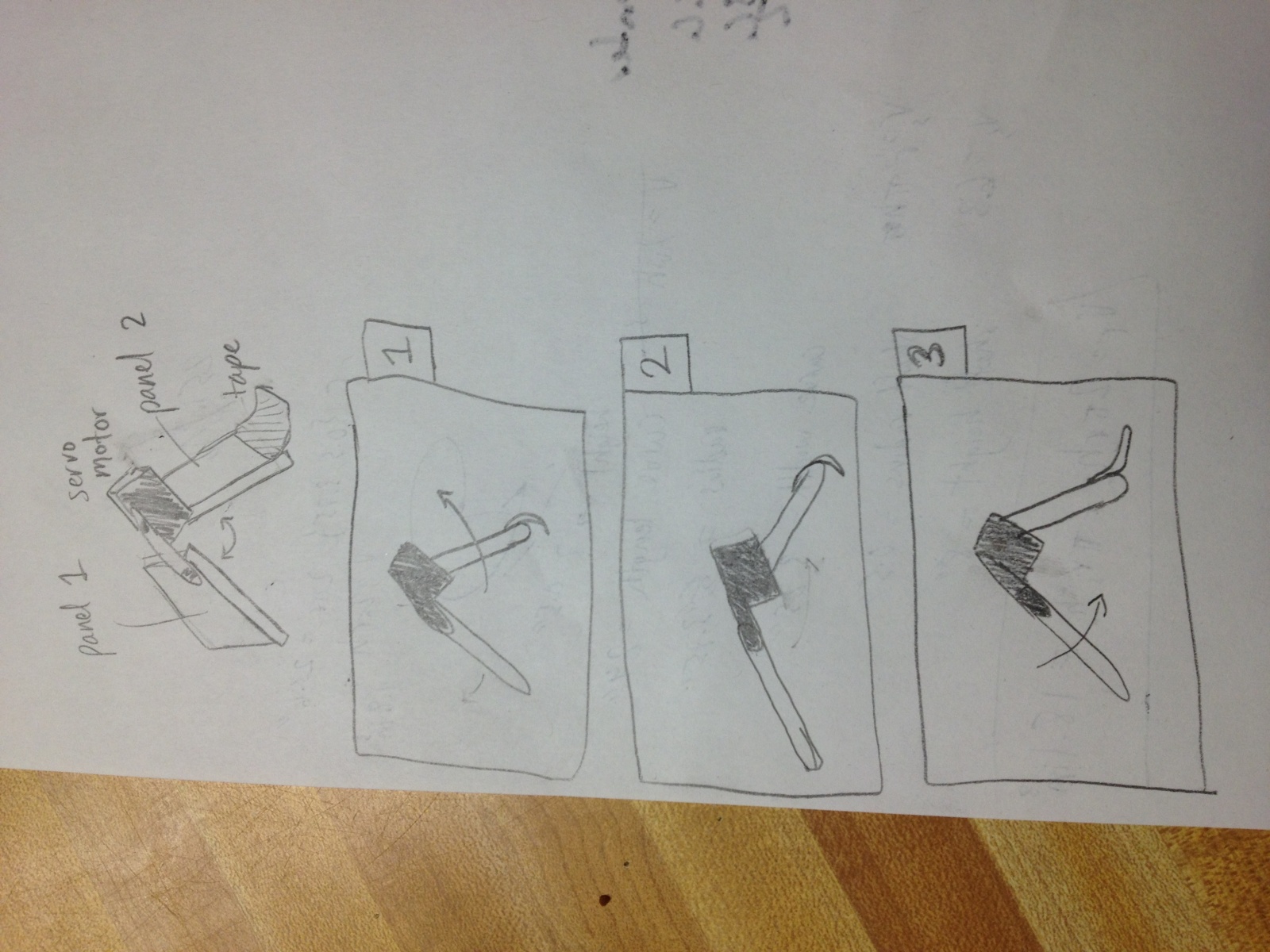
Here is a diagram on how the Z Flipper would move.


Parts List
3 Cardboard plates made from gum packaging.
2 stepper motors
1 arduino microcontroller
2 long, stiff wires for attaching the motors
tape
jumper wires
Instructions
First construct the flipper. Attach the motors to the plates using tape and wires. At a joint, the motor body connects to one of the plates using tape. The motor arms connect to the other plate. This connection is much weaker and needs the wire to reinforce it. When that’s done, use the jumper cables to connect the motors to the arduino. Finally, upload the code and let it go. The code is designed to turn the motor, wait a set amount of time, and then turn the other motor. And so on.
Testing
Video of the Z-Flipper. We were able to construct the flipper mechanism, but the motors were too weak to move unaided.
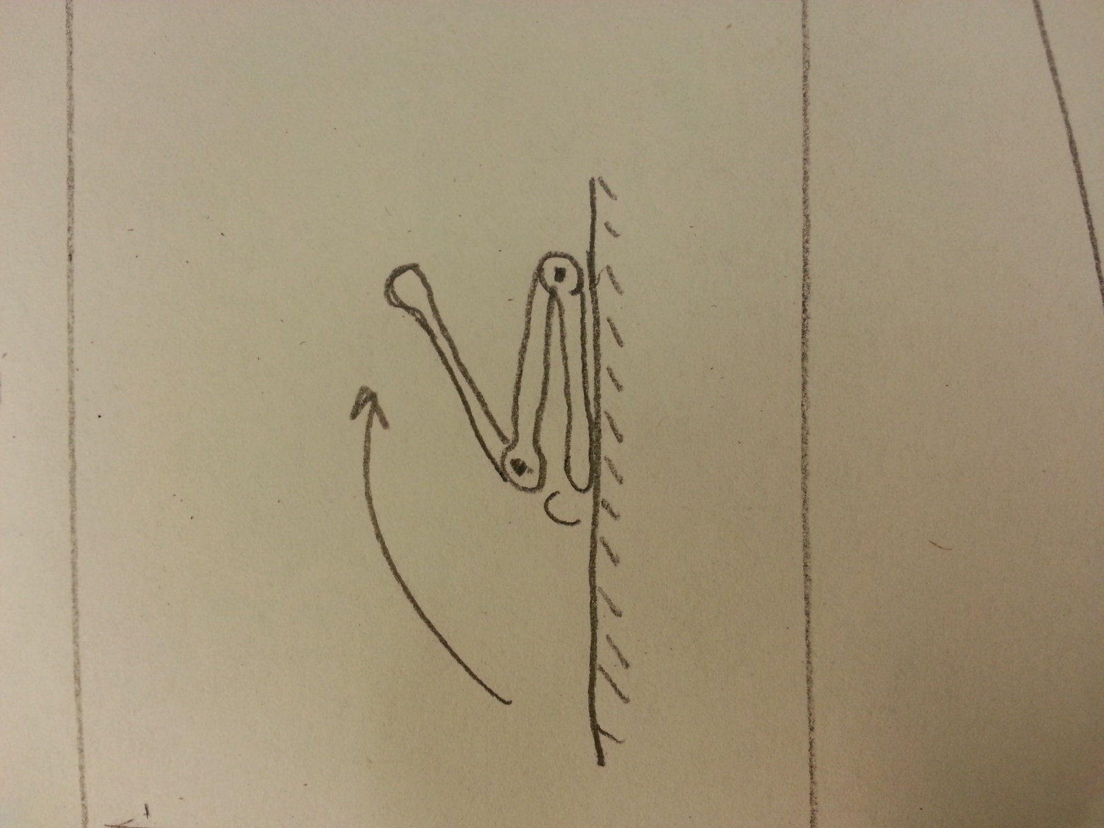
In order to salvage a workable robot, we stripped off the second joint, leaving only 2 panels connected by a servo motor. Now the robot was basically a hinge that could open and close. Instead of flipping over itself, the robot would now move using an inch-worm type motion. To create forward motion, I covered the back panel in smooth electrical tape and put a flap of scotch tape on the front panel. When bending open, the flap would curl under itself and slide forward. When bending close, the sticky side would catch on the table and pull the rest of the robot forward. I call it the Wormotron. Check out our new diagrams and video.
Diagram
Wormotron in action.
Arduino Code
/*
Lab 3, COS 436
Z Flipper Robot
Group 24: The Cereal Killers
*/

#include

int jointPinA = 9;
Servo servoA;
int angleA = 0;
int steps = 10;
int on = 1;

void setup() {
  servoA.attach(jointPinA);

  Serial.begin(9600);
  Serial.println("Ready");
}


void loop()
{
  if(on == 1) {
    for(int i = 0; i < steps; i++)
    {
      openJointA();
      delay(15);
      closeJointA();
      delay(15);
    }
    on = 0;
    servoA.detach();
  }
}

void openJointA() {
  // scan from current position to 180 degrees
  for(; angleA  0; angleA--)
  {
    servoA.write(angleA);
    delay(15);
  }
}