
Connie, Angela, Kiran, Edward
Group #13
Robot Brainstorming
- Peristalsis robot: Use servo motors with rubber bands to get it to move with elastic energy somehow
- Helicopter robot: spinning rotor to make it fly (like the nano quadrotor except less cool)
- Puppet robot: use motor or servos to control puppet strings
- Crab style robot: crawling on six legs
- Robo-ball: omnidirectional rolling
- 3- or 4-wheeled robot: like a car
- fixed magnitude offset in motor speed of 2-wheel robot — move in squiggles
- Magnet-flinging robot: has a string with a magnet attached to it, uses a motor catapult to throw it forward, latches on to nearest magnet, and then has another motor to reel in the string. rinse and repeat
- Flashlight-controlled robot: use photosensors and it only moves if a lot of light is shone on it
- Tank robot: use treads around wheels
- Hopping robot: uses a servo to wind up a spring and fling itself forward
- Inchworm robot: moves like an inchworm
- Sidewinder robot: moves like a sidewinder
- Hot air balloon: make a fan that blows air past a heated element into a balloon (might be unsafe)
- Sculpture: moves linked magnets in constrained area with a magnet on motor (more of an art piece than a robot)
Red light Green light Robot
Our robot is a two-wheeled vehicle made of two paper plates. It plays red light green light with the user: when the user shines a flashlight on the vehicle, it moves forwards. It stops moving when the light stops shining on it.
We made this because it was a simple way to make a robot that was still interactive, rather than just moving arbitrarily on its own. While our electronics worked exactly as planned, it was very difficult to create a chassis that would allow the motor to drive the wheels while being able to support the weight of the battery pack, arduino, and breadboard. In fact, our robot didn’t really work – it just shuddered slightly but didn’t move. This was primarily due to the weight of the components; we’d need a more specialized set of parts like Lego or some structural kit with gears instead of sticks, plates, and tape. It was especially difficult to find a way to connect the smooth motor shaft with the plate (although we did get a very good attachment with just one plate and a motor).

Here is a shot of our robot in action, or to be more accurate, robot inaction.
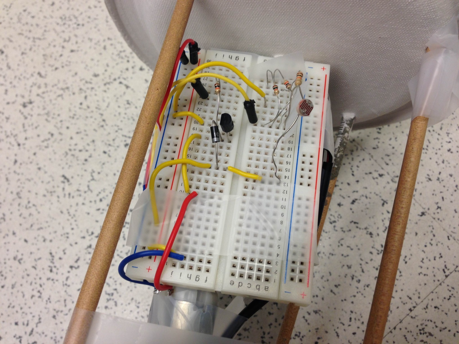
In this picture you can see the electronics as well as the attachments of the components and dowels to the wheels.

This is the design sketch for the Red light Green light robot
Parts List
- Arduino Uno with battery pack
- Breadboard (as small as possible!)
- Wires
- Photoresistor
- PN2222 Transistor
- 1x DC motor
- 1x 1N4001 diode
- 1x 270Ω resistor
- 1x 3KΩ resistor
- 2x paper plates
- 1x photoresistor
- Wooden dowel, at least 40cm long
- Tape
- Paperclips
Instructions
- Attach the photoresistor from 5V to analog pin 5 through a 3KΩ pulldown resistor
- Attach the motor as shown in http://learn.adafruit.com/adafruit-arduino-lesson-13-dc-motors/breadboard-layout; use the diode between the two sides of the motor, attaching the middle pin of the transistor to digital port 3 through the 270Ω resistor
- Measure the ambient light reading from the photoresistor, and then the flashlight reading, and set the threshold appropriately between the two readings
- Punch holes as appropriate in the paper plate wheels (small holes in the center, two larger ones opposite each other).
- Unfold a paperclip and wind one half around the spinning axle of the motor. Tape the other half flat on the outside of one wheel.
- Break the dowel in half and poke the halves through the larger holes in the wheels, tape them in place.
- Securely attach arduino, breadboard, and battery pack in a solid block. Connect the motor appropriately, and make sure the photoresistor faces upward.
- Unfold a paperclip and securely tape half onto the arduino/breadboard/batteries contraption. Unfold the other half and poke a straight prong through the paper plate not attached to the motor.
Source Code
/* Red light Green light robot
 * COS436 Lab 3, group 13
 */
int motorPin = 3;
int photoPin = A5;
int motorspeed = 0;
int threshold = 830;

void setup()
{
  Serial.begin(9600);
  pinMode(motorPin, OUTPUT);
  pinMode(photoPin, INPUT);
}


void loop()
{
  Serial.println(analogRead(photoPin));
  if (analogRead(photoPin) > threshold) {
    motorspeed = 200;
  }
  else {
    motorspeed = 0;
  }
  analogWrite(motorPin, motorspeed);
  delay(40);
}