Green Choi (ghchoi@)
Peter Yu (keunwooy@)
Vivian Qu (equ@)
Jae Lee (jyltwo@)
Rainbow Tower:
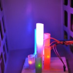
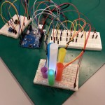
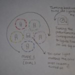
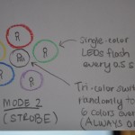
We used five single-color LED lights positioned in a circle around a tri-color LED light. All the lights can be controlled by a dial (potentiometer) and a button. The LEDs were covered with colored straws to make a visually comforting diffuser. The button switched between modes: DIAL and STROBE modes. When the mode is DIAL, the user can one-by-one turn on each of the single-color LED lights while the tri-color LED light changes to the corresponding single-color LED light that was just turned on. When the mode is STROBE, the single-color LED lights flash every 0.5 seconds. The main tri-color LED stays on and changes to a random color every 0.5 seconds.
We were inspired by the many different types of night lights or children’s toys which change colors. We wanted to also build an interactive, colorful set of lights that could be changed to fit the user’s color preferences. Plus, it makes us really happy to play with the multiple lights!
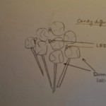
The device responds very well to the user inputs. But in the future, we would like to make the setup more stable by attaching the base of straws to foam core or cardboard. We wanted to use a 7-segment display to show the current mode, but we didn’t have enough digital I/O ports available. So if we could use more arduinos, more functionalities (like displaying the current mode) would be possible. There is also a lot of potential for design expansion if there were more LEDs and arduinos available, so the lights and straws could be added to create a bigger Rainbow Tower!
Photos + Videos:
- Rainbow Tower
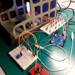
- Display Wiring
- Final Setup
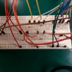
- Setup — no straws
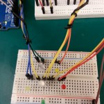
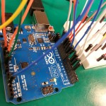
- Wiring
- More Wiring
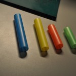
- Straws
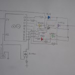
- Circuit design
- DIAL mode
- STROBE mode
- Possible straw configurations
- Lollipop Design
- Bop-It Design
Parts Used:
- Arduino UNO R3 (1)
- SoftPot (1)
- Button (1)
- Basic LED (5)
- Tri-Color LED (1)
- Colored Straws (6)
- 330 Ohm Resistors (9)
- Breadboard (3)
- Wires
Instructions for Recreating:
- Position the 5 one-color LED lights in a circle configuration on the breadboard. Place the tri-color LED in the center. Make sure there is enough space to cover each LED with a straw. Wire the one-color LEDs — connect the positive end through a resistor to the arduino’s digital I/O ports (we used ports 9, 10, 11, 12, 13) and the other end to ground, using a second breadboard to hold all the resistors if necessary. Wire the tri-color LED by connecting three legs to digital I/O ports (we used ports 3, 5, 6) and the longer leg to ground.
- Cover all 6 LEDs with appropriate colored straws. Cut the straws to varying size, if desired.
- Use another breadboard to set up the button and the potentiometer. For the button, connect one leg to a digital I/O port (we used port 8). Connect the same leg on the opposite side through a resistor to ground. Finally, connect the opposite leg to 5V.
- For the potentiometer, connect the rightmost leg to ground. Connect the leftmost leg to 5V. The middle leg is connected to analog input (we used port A2).
- Upload the code, and test it out!
Code:
/*
The Rainbow Tower -- awesome diffuser with straws
*/
// Set the I/O pin numbers.
const int blueLed = 13;
const int yellowLed = 12;
const int redLed = 11;
const int greenLed = 10;
const int purpleLed = 9;
const int multiRLed = 6;
const int multiGLed = 5;
const int multiBLed = 3;
const int potPin = 2;
const int buttonPin = 8;

// Colors for tri-color LED
// Red
const byte r1 = 255;
const byte g1 = 0;
const byte b1 = 0;
// Orange
const byte r2 = 255;
const byte g2 = 128;
const byte b2 = 0;
// Yellow
const byte r3 = 255;
const byte g3 = 255;
const byte b3 = 0;
// Green
const byte r4 = 128;
const byte g4 = 255;
const byte b4 = 0;
// Blue
const byte r5 = 0;
const byte g5 = 0;
const byte b5 = 255;
// Purple
const byte r6 = 128;
const byte g6 = 0;
const byte b6 = 255;

boolean changed = false;
int buttonMode = 0;
int buttonVal = 0; // Button
int potVal = 0; // Potentiometer
int bulbVal = 0;
long interval = 500; // Blink time (0.5 s)
long previousMillis = 0;
int flickerState = LOW;

void setup() {
    // Set the digital pins as output:
    pinMode(blueLed, OUTPUT);
    pinMode(yellowLed, OUTPUT);
    pinMode(redLed, OUTPUT);
    pinMode(greenLed, OUTPUT);
    pinMode(purpleLed, OUTPUT);
    pinMode(multiRLed, OUTPUT);
    pinMode(multiGLed, OUTPUT);
    pinMode(multiBLed, OUTPUT);
}

void loop()
{
    // Tri-color LED is always lit.
    unsigned long currentMillis = millis();

    // Read the mode.
    buttonVal = digitalRead(buttonPin);
    if (buttonVal == HIGH) {
        changed = true;
    }
    if (changed && buttonVal == LOW) {
        buttonMode++;
        buttonMode %= 2;
        changed = false;
    }
    // DIAL mode
    if (buttonMode == 0) {
        for (int i = 9; i <= 13; ++i) {
        digitalWrite(i, LOW);
        }
        potVal = analogRead(potPin);
        bulbVal = map(potVal, 0, 1023, 9, 17);
        for (int i = 13; i >= bulbVal; --i) {
            digitalWrite(i, HIGH);
        }
        if (bulbVal == 9) {
            analogWrite(multiRLed, r6);
            analogWrite(multiGLed, g6);
            analogWrite(multiBLed, b6);
        }
        if (bulbVal == 10) {
            analogWrite(multiRLed, r5);
            analogWrite(multiGLed, g5);
            analogWrite(multiBLed, b5);
        }
        if (bulbVal == 11) {
            analogWrite(multiRLed, r4);
            analogWrite(multiGLed, g4);
            analogWrite(multiBLed, b4);
        }
        if (bulbVal == 12) {
            analogWrite(multiRLed, r3);
            analogWrite(multiGLed, g3);
            analogWrite(multiBLed, b3);
        }
        if (bulbVal == 13) {
            analogWrite(multiRLed, r2);
            analogWrite(multiGLed, g2);
            analogWrite(multiBLed, b2);
        }
        if (bulbVal == 14) {
            analogWrite(multiRLed, r1);
            analogWrite(multiGLed, g1);
            analogWrite(multiBLed, b1);
        }
        if (bulbVal == 15) {
            analogWrite(multiRLed, 0);
            analogWrite(multiGLed, 0);
            analogWrite(multiBLed, 0);
        }
    }
    // STROBE mode
    else {
        if (currentMillis - previousMillis > interval) {
            previousMillis = currentMillis;

            if (flickerState == LOW)
                flickerState = HIGH;
            else
                flickerState = LOW;

            for (int i = 9; i <= 13; ++i) {
                digitalWrite(i, flickerState);
            }
            analogWrite(multiRLed, 30);
            analogWrite(multiGLed, 30);
            analogWrite(multiBLed, 30);
        }
    }
}

