
John Subosits
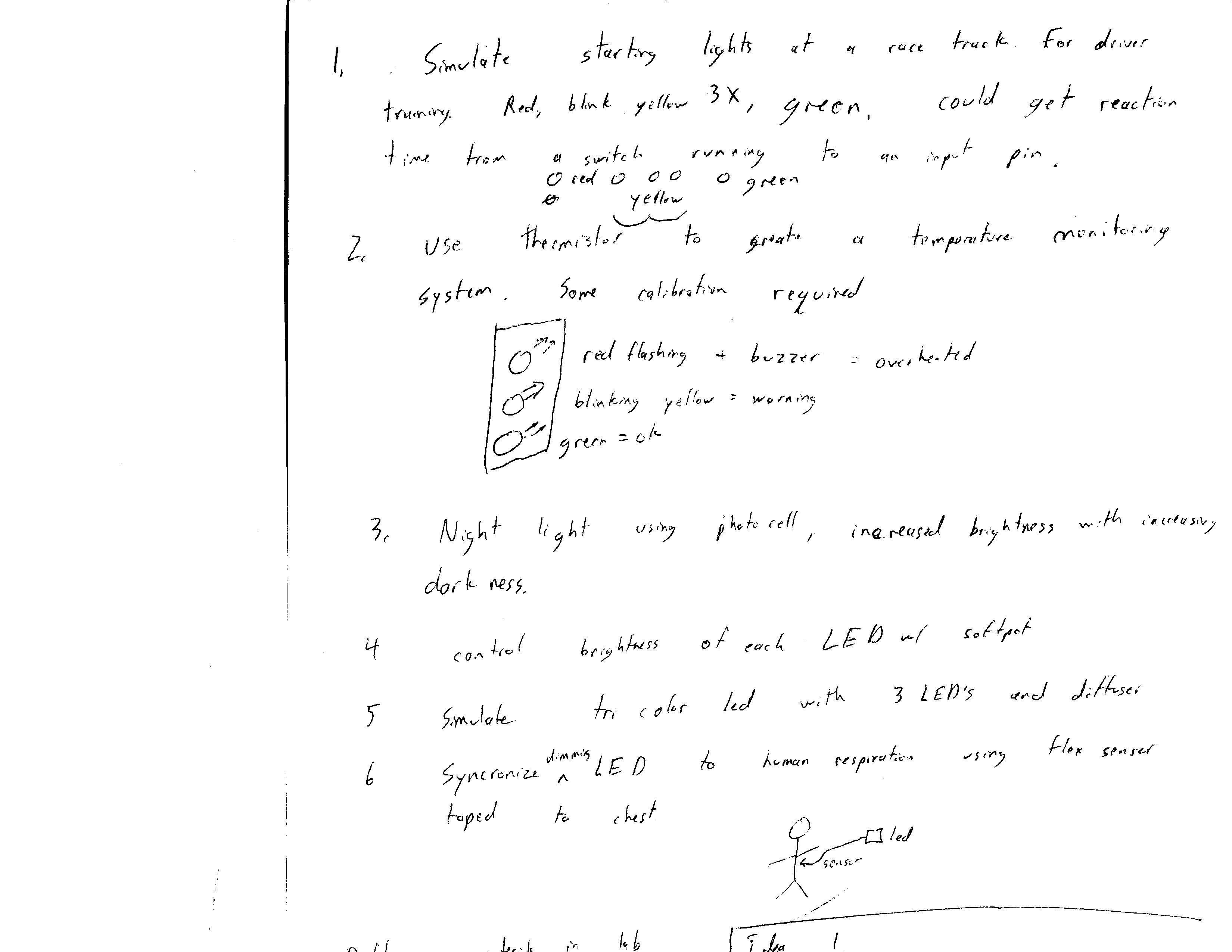
Here are some ideas for the third part of the lab. Finding a way to make the diffuser useful was difficult.
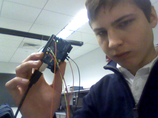
Click on the picture for a better view.
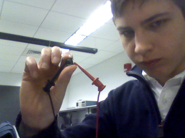
I decided to build the first idea, a device to improve the reaction times of people who drag race. Three LED’s, red, yellow, and green were used to simulate the “tree” of lights that is used to signal the beginning of a race. Several pieces of cellophane tape were used as a diffuser for the LED’s although napkins and a water bottle were also considered. The red light illuminates, the yellow flashes three times, and then the green light comes on. When this happens the person using the device pushes and holds the switch button supplied in the kit as they would the accelerator pedal if they were racing. If they false start, only the red light illuminates while a clean start lights all three lights. After a few seconds, the sequence begins again. The system was reasonably fun to play with, and I consider it a success. Some improvements would be adding additional yellow LED’s to allow them to stay lit for the countdown (more realistic), using a switch that mounts to the breadboard or one that has a form factor like a clutch pedal, and using the computer to report reaction times to track improvements.
Here are some videos of the system in action and a few pictures of its layout.
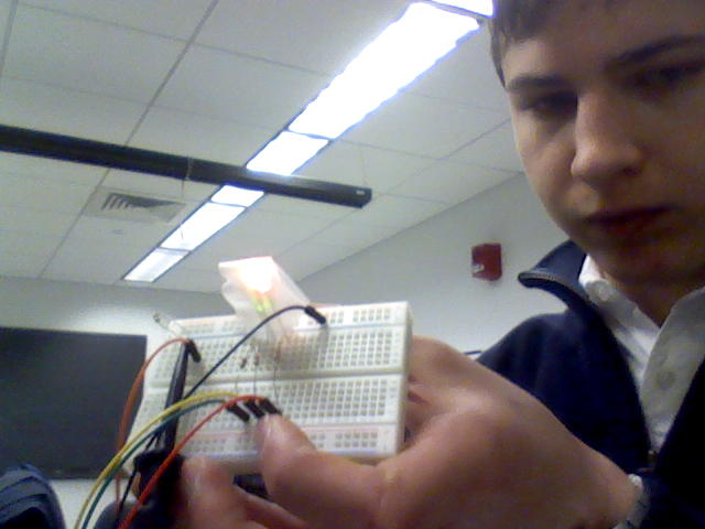
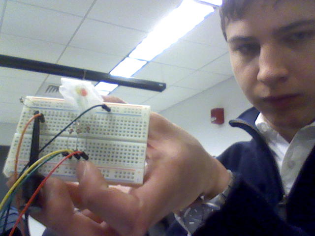
Parts used:
Yellow, green, and red LED 1 each
330 ohm resistor x 3
10 k resistor
12 mm button switch
Miscellaneous jumper wires and clip leads
Breadboard
Arduino
Instructions for construction:
Connect pins 11, 10, and 9 through independent 330 ohm resistors and red, green and yellow LED’s respectively to ground. Also connect the switch between 5V and Pin 2. A 10 k pull-down resistor connected to ground was used on Pin 2. Clip leads should be used, as the switch does not make good contact with the breadboard. The code below was used to control everything.
// This code is inspired by the Blink example included with the Arduino.
// Also some inspiration is taken from the Button tuturial available at
// http://www.arduino.cc/en/Tutorial/Button
  int red = 11;
  int green = 10;
  int yellow = 9;
  const int buttonPin = 2;     // the number of the pushbutton pin
  int buttonState = 0;

void setup() {
  // put your setup code here, to run once:

  pinMode(red, OUTPUT);   // sets the pin as output
  pinMode(green, OUTPUT);   // sets the pin as output
  pinMode(yellow, OUTPUT);   // sets the pin as output
  pinMode(buttonPin, INPUT);
 }

void loop() {
  // put your main code here, to run repeatedly:
  for (int i = yellow; i <= red; i++) {
    digitalWrite(i, LOW);
  }
  delay(5000);
  digitalWrite(red, HIGH);
  delay(500);
  for (int i = 0; i < 3; i++) {
    digitalWrite(yellow, HIGH);
    delay(150);
    digitalWrite(yellow, LOW);
    delay(350) ;
  }
  buttonState = digitalRead(buttonPin);
  if (buttonState == HIGH) {
    delay(4000);
  }
  else if (buttonState == LOW) {
  digitalWrite(green, HIGH);
  digitalWrite(yellow, HIGH);
  delay(3000);
  }

}