
Group Members
- David Dohan
- Miles Yucht
- Andrew Cheong
- Shubhro Saha
Description
In a moment of ‘70s nostalgia during our lab brainstorming session, we decided to build a lava lamp. Not only did we want to reproduce the brilliance of the original lava lamp, but also our objective was to creatively extend its capabilities. In particular, our innovative lava lamp allows the owner to change the lamp’s color/brightness with an interactive slider and switch between color/brightness modes witha push button. The milk and oil lava produced a unique texture of very fine bubbles which act as an excellent light diffuser. Our final product turned out to be a great success. It’s not perfect, but it changes color according to the user’s input and turns on when the room lights are turned off. The code written for this interactivity is our proudest feature, and there are several areas of improvement. The lava lamp is hardly robust—electrical connections inside the test tube had to be completed with paper clips because alligator clips were too large. With more time, we would’ve made it less obvious that the lamp is a crude Princeton water bottle with a test tube dropped inside of it. However, it demonstrates a proof of concept, and it is easily expandable in the event that one would like to use more LEDs or add more modes. Additionally, we could improve the smoothness of the mapping from linear values (from the soft pot) to the color wheel.
Photos of Sketches
We considered making a reaction time game with Arduino.

We considered making an LED change brightness in response to ambient light levels.
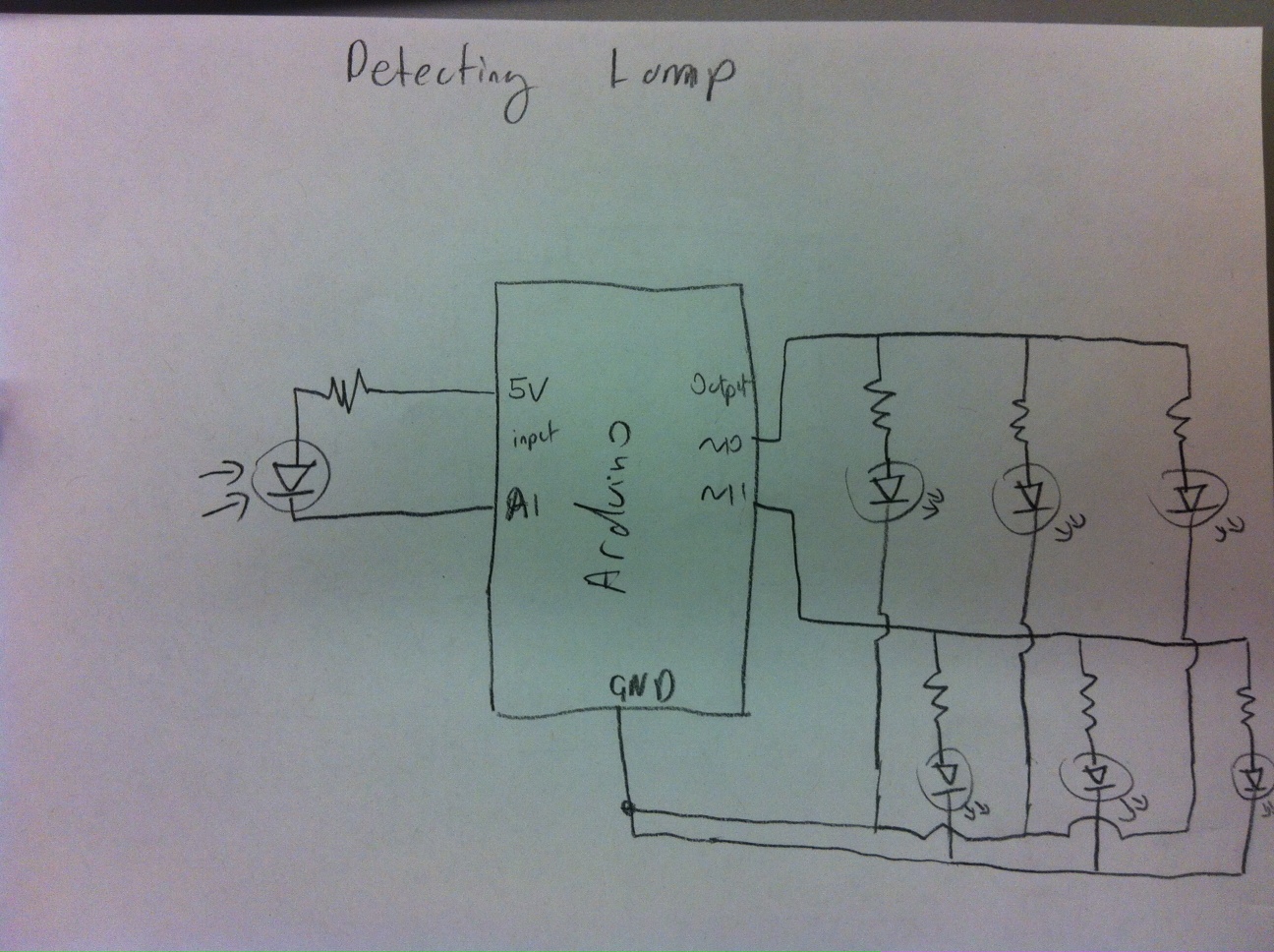
This is our final schematic for the lava lamp.

Video
Here’s a YouTube video of our final system in action.
Parts
- Arduino Uno
- Small water bottle
- 12 mL test tube
- Tricolor LED
- 5 330-ohm resistors
- Photoresistor
- Button
- Softpot
- Vegetable Oil
- Teaspoon of milk
Instructions
There are four components to this build: the lava and its container, the tri-color LED light source, the interactive controls (i.e., the softpot, photoresistor, and button), and the Arduino with associated code. We first built and tested the light source with the Arduino before putting it into the test tube. When building the light source, make sure that the way you connect the LED to the rest of the circuitry makes a difference: it needs to be slim enough to fit inside a test tube. To build the light source:
- Connect pin 9 on the Arduino to a 330-ohm resistor, and in series connect the cathode on the tri-color LED corresponding to the red LED. For the second connection you will want to use longer cables so that they can reach from your breadboard to the LED once it is suspended in the lava lamp.
- Repeat step 1 with pin 10 on the Arduino to the green cathode and pin 11 on the Arduino to the blue cathode.
- Connect the tri-color LED anode to ground, again using a long cable.
- Because these wires all have to be very close to one another inside of the test tube, we recommend using a small amount of electrical tape between connections so that you don’t short out any connections.
To build the interactive component (softpot and button):
- Connect the softpot to the breadboard with pin 1 at 5V+, pin 2 to A1 on the Arduino, and pin 3 to ground.
- Connect the button using a 330-ohm resistor according to the Arduino Button tutorial (http://arduino.cc/en/tutorial/button).
- Connect the 5V+ to a 330-ohm resistor in series with the photoresistor. Connect A0 on the Arduino to the conductor between these two resistors, and connect the other end of the photoresistor to ground.
To build the lava lamp:
- Fill the bottle with half water, half vegetable oil up to about ⅘ of the way.
- Add in approximately a teaspoon of milk.
- Shake vigorously.
- The resulting mixture should have a slightly yellow/white color but also have a large number of small bubbles (resulting from the mixture of water and oil).
Assembling the final product:
- After finishing the LED assemblage, insert the LED into a test tube such that, when the test tube is lowered into the bottle, the LED will be approximately half-way down the bottle. The point of the test tube is to keep the LEDs dry and away from the oil-milk lava. If you’re having trouble (as we did), you can try a larger test tube. Ideally, you should solder and insulate the leads, but since we are not allowed to solder, our makeshift solution was to use paper clips to extend one of the cathodes so that we could connect to it using an alligator clip. Also, a small amount of oil on the inside of the test tube acts as a lubricant, so it is then a bit easier to slide the LED assembly inside.
- Lower the test tube into the lavalamp, and use tape to hold the test tube in place inside the bottle.
- Play!
Usage
There are 4 basic modes: one to set the color of the LED and one to set the brightness. Switching between modes is accomplished using the button. In the color mode, the softpot controls only the color of the LED along a color wheel. In the brightness mode, the softpot controls the brightness of the LED without affecting its color. The third and fourth modes are for cycling through different colors By the nature of the softpot, as soon as one stops touching the component, the resistance returns to a steady state. Instead of trying to identify instances when this happens, we also made a fifth mode that saves the current settings. In this mode, the softpot has no effect on the color or brightness. In the future, we might add indicator lights to identify what mode we are in at any given time, even though it is really easy to find out (just touch the softpot and see how the light changes).
Source Code
// Lava lamp code for HCI (COS 436/ELE 469)

/*
  The RGB LED has three cathodes and a common anode. Each cathode
  corresponds to a color in the LED and is independently
  controllable.
*/

//for color of the tricolor LED only. determines the size of the
//set of values over which each color fades on/off while using the
//softpot.
int range = 300;

/*
  In each set of variables RGBLED_xxxx and RGB_x_mid, the former
  corresponds to the pin being used for color xxxx. The latter
  corresponds to the softpot value at which color x is at its greatest
  brightness.
*/
int RGBLED_Red = 9;
int RGB_R_mid = 100;

int RGBLED_Blue = 10;
int RGB_B_mid = 500;

int RGBLED_Green = 11;
int RGB_G_mid = 900;

//Arduino pinouts for each component
int softpot = A0;
int photosensor = A1;
int button = 2;

//current color
int color = 0;

//current values for the intensities of each LED color
int rgb_r, rgb_g, rgb_b;

// brightness ranges from 0 to 1
double brightness = 1.0;

// mode is:
//   0: set color
//   1: set brightness
int mode = 0;

// psthreshold is the least amount of light needed to activate the lights
int psthreshold = 850;

// state variable is:
//	0: off
//	1: on
int state = 1;

//calculates the intensity of a color based on the current value of
//the softpot, the color’s RGB_x_mid value, and the range variable.
int getBrightness(double mid, double cur) {
  int t1 = abs(mid - cur);
  int t2 = abs(mid - (cur - 1024));
  int t3 = abs(mid - (cur + 1024));

  int test1 = min(t1, t2);
  int minimum = min(test1, t3);

  if (minimum > range) return 0.0;

  return 255 * (range - minimum) / range;
}

//sets the color for all three colors in accordance with the current
//softpot value
void setVals(int cur) {
  if (state == 1) {
	rgb_r = getBrightness(RGB_R_mid, cur);
	rgb_g = getBrightness(RGB_G_mid, cur);
	rgb_b = getBrightness(RGB_B_mid, cur);
  }

  writeToLED();
}

//sets the brightness of the LED according to the current
//softpot value
void setBrightness(double cur) {
  if (state == 1)
	brightness = cur / 1024;

  writeToLED();
}

//actually sets the PWM pins to the values dictated by the current
//color and brightness
void writeToLED() {
  analogWrite(RGBLED_Red, rgb_r * brightness * state);
  analogWrite(RGBLED_Blue, rgb_b * brightness * state);
  analogWrite(RGBLED_Green, rgb_g * brightness * state);
}

//switch between modes
void toggleMode() {
  mode = (mode + 1) % 5;
}

//setup each LED and button
void setup() {
  pinMode(RGBLED_Red, OUTPUT);
  pinMode(RGBLED_Blue, OUTPUT);
  pinMode(RGBLED_Green, OUTPUT);
  pinMode(button, INPUT);

  Serial.begin(9600);
}

void loop() {
  // Check to see if there is light in the room using the
  // photoresistor. If so, set the output to 0. Otherwise, use the
  // softpot.
  int current_light = analogRead(photosensor);
  int current_soft = analogRead(softpot);
  int button_state = digitalRead(button);

  if (button_state == HIGH) {
	while (digitalRead(button) == HIGH);
	toggleMode();
	Serial.print(mode);
	Serial.print("\n");
  }

  if (mode == 0) {
	setVals(current_soft);
  } else if (mode == 1) {
	setBrightness(current_soft);
  } else if (mode == 3) {
	color = (color + 1) % 1024;
	setVals((int)color);
  } else if (mode == 4) {
	color = (color + 1) % 2048;
	setVals(color/2);
  }
}