Group 4 – Team TFCS – Collin, Dale, Raymond, Farhan
Short Description
We built a robot consisting of two “feet” connected by a paper towel tube. Each foot was a small breadboard plugged into a row of male header pins. The exposed ends of these pins were all bent at a 40 degree angle in the same direction. A DC motor was secured to the top of each foot, and each motor was attached to a single propeller blade with a small weight at the end. We put our Arduino in a “cockpit” which we built into the center of the paper towel tube. The motors were then plugged into the Arduino, and the Arduino was given a battery pack so that it could run without being tethered to a computer. Our group first decided that we wanted to build a robot that moved by vibration. We were motivated to make this decision because of the inherent weakness of DC motors. We didn’t want our robot to move randomly, however, so we decided to encourage the robot to move in a particular direction by angling the bristles on its feet so that the friction of moving forward would be less than that of moving in any other direction. Then, inspired by the neighboring car lab, we decided to go a step further and make our robot steerable by having two independently running feet. The concept is similar to that of a tank. The final product was viewed as a success. The robot moved as desired, and it could run on its own via battery power. However, it is a little slow. If we were going to redesign it, we would probably want to find a better way to get the feet to vibrate. This would probably involve a different configuration for the motor and its attached weights. We could also come up with a better design for the feet, perhaps using fewer bristles or some material other than metal.
List of Brainstormed Ideas
- Toothbrush Rumble Bot
- Three-Wheeled Vehicle
- Hovercraft
- Grappling-Hook Bot
- Ladder Crawler
- Magnetic Surface Crawler
- Segway
- Rudder Boat
- Fanboat
- Hot Air Balloon
- Blimp
- Hybrid Airship (Blimps connected to propellers)
- Flywheel Car
Sketches
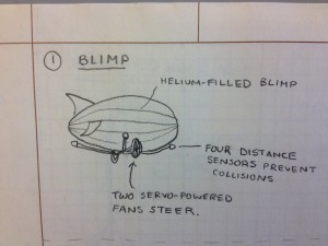
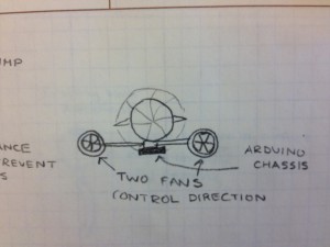
Arduino-powered blimp is filled with helium. Fans on either side of the underbelly control which direction the blimp moves.
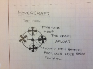
Arduino hovercraft consists of a plastic ring with an Arduino at its center. Evenly spaced around the ring are four fans powered by motors that allow the hovercraft to “hover”.
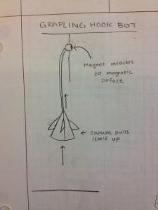
Grappling hook bot launches a ball with a small magnet and rope attached. It attaches itself to a magnetic surface and pulls itself upwards by winding the rope around an axle.

Air compression tube is compressed by motor and launches the grappling ball. Rope attached to motor axle pulls chassis upward along rope.

Ladder Crawler consists of two hooks attached to telescoping arms. An Arduino moves the arms in and out, and the hooks grab onto each subsequent rung of the ladder.

The magnetic surface climber moves by coordinating its arm movements with the turning on an off of two electromagnets.
The Product

Parts List
-2 Small DC Motors
-1 Paper Towel Tube
-1 Arduino
-Jumper Wires
-Tape
-2 Small Weights (like screw nuts)
-2 Mini Breadboards
-2 Rows of Male Header Pins
-Victory Flag
-1 Battery Pack
-1 9V Battery
Instructions for Creation
a. The premise of Rumba is that its two “feet”, which consist of rows of angled wire, are designed in such a way that when they are vibrated, they move in a direction determined by the angle of the wire. Rumba has two feet connected by a paper-towel-tube body. When the left foot is vibrated and the right foot is not, Rumba pivots around its right foot. Conversely when its right foot alone is vibrated. In this way, we can control which direction Rumba moves in.
b. Thus, in order to make a Rumba, we have to find a way create vibrations. To do this, attach an asymmetric servo horn to the axles of each of two small DC motors. We then attach a very small weight (like a nut for a screw) to the end of the servo horns. When the asymmetric horns turn, they continuously move the center of mass of the system. The result is that the motor vibrates. Securely attach each motor (with strong tape) and servo horn to two mini breadboards so that the servo horn hangs off the side and can rotate freely.
c. Now we must create the angled bristles for the feet of our Rumba, which will be attached to the bottom of the two breadboards. These will be made out of male-to-male headers. For each breadboard, measure one row of headers with enough pins to line the long outer edge of the breadboard. Attach the headers to the breadboard. Bend the pins that are now sticking out of the breadboard to be about 40 degrees from the breadboard. These are the breadboard feet.
d. Rumba’s body consists of a cardboard paper towel tube. Tape both breadboards to either end of this tube so that the angled feet face down, making sure to avoid the feet when taping the breadboard.
e. The brain of Rumba is an Arduino. Load the code below to the Arduino. It is programmed to turn each motor so that Rumba moves in an “interesting” way. To attach the Arduino to Rumba, first create a square tray chassis from the box that Arduino comes in. Cut a hole in the chassis where the round power plug will attach to a battery pack. To attach the chassis, we cut a square from the *top* of the center of paper towel tube, so that the bottom half of the tube is intact and the chassis can securely slide into the opening Attach a battery pack (we used a 9V battery pack) to the Arduino and place it along with the Arduino in the chassis. Tape the chassis to the paper towel role.
f. Now we attach the motors to the Arduino, by connecting the power wire to ports 3 and 5, and the ground wire to ground.
g. Turn on the power. Your Rumba should now be functional!
h. Optional: Add victory flag.

