
GROUP MEMBERS:
- Neil Chatterjee (neilc@)
- Alan Thorne (athorne@)
- Vivian Qu (equ@)
- Harvest Zhang (hlzhang@)
PART I:
- Kinect DJ system: Uses gestures and body motion from skeleton data to control music mixing.
- Air guitar: a flex-sensor based air guitar for Xbox games.
- Automated third arm: Kinect or Android-based robotic arm for assisting in building, soldering, etc. A functional helping hands tool.
- Kinect Haptic Vision: Vibration based on Kinect’s forward vision to help blind people see by feel from depth sensor data.
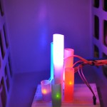
- Shower rave: LED filter through water streams to color the stream optically; add music and make it into a whole dance system.
- Posture Adjusting Shoes: using weight sensors and motors, readjust the inside bottom surface of the shoes to improve posture.
- Sychronized Firework Launcher: Arduino and smartphone controlled synchronized fireworks launcher for private fireworks shows
- NFC Information Platform: NFC controlled information booths throughout a building, accompanied by a database on an app and a map. Get close to get info
- Kinect Gesture Analyzer: Observe which physical tics people use while giving talks and critique.
- Turn Signal Clothing: Bicycle shirts that have LED turn signals for safety.
- Kinect room analyzer + home decorator: Kinect scans a room and then uploads a mesh of the surrounding area to alter in photoshop.
- Smart Clothing — Breathalyzer: measures people’s health; Drunkard’s shirt that measures pulse, temperature, and BAC and reports safety.
- Laser tag T-Shirts to create a more visual experience.
- Real-life angry birds with tracking data and projectile’s simulated with Kinect motion.
- Symmetric face properties: Analysis of a person’s face to reveal how symmetrical they really are.
- Kinect-controlled quadcopter/RV car. Kinect motions feed data to an Arduino to remotely control these electronics.
- 3D Kinect scanner that rotates an object on a platform to create a point cloud of the object.
- Reflex games that use an arduino to interpret response time.
- Triangulating gunshots using Raspberry Pis and sound sensors spaced throughout a city, room, building, etc.
- Arduino swiffer/roomba that automatically navigates the floor of a room to clean.
- Arduino door opener that contains a security presence to allow access for some people
- Nest like system that allows general control of the homeostasis of a house.
- Security cam from bike stealers that texts you if your bike has been stolen.
- Arduino oscilloscope that measures voltage and current by using variable resistors. Additionally, Processing would create a plot.
- Fire safety ALERT button that sends texts to everyone in a hall.
- Backpack dog follows you around by tracking your motion with a Kinect.
- Predicting lightning strikes using ozone sensors.
- Methane Interpolator: determine where cows are or a fart detector that uses an assembly of these in an enclosed area.
- Automatic garbage can: to follow drunk people around in case they can no longer handle themselves.
- Electric Bike Conversion optimizes power usage during a bike and can provide uphill assist.
- Laptop controller for when you’re lying down (hard to see / use keyboard / balance weight).
- Automatic page turner for books.
- Planetarium (lasers) that uses servos to project images onto a screen.
- Transparent screens (lasers) that uses servos to project lasers onto an opaque glass
- Keyboard pants that allow anyone to type on themselves.
- Giant touchscreen made out of an assembly of smaller phones.
- Phone tag: Mobile game that allows you to play tag with your cellphones.
- Bluetooth phone glove on your hand so that you can talk with your gloves.
- Measure foot pressure and adjust for correct walking position to improve posture.
- Theremin instrument simulated using the Kinect.
- Bluetooth backup camera to be implemented in cars for a cheap solution to alternatives.
- Auto-instagram shots uses Arduino to easily and quickly upload certain images to Instagram (ethernet shield).
- Home automation wake up system to integrate a morning routine into an electrical system
- Nightmare detector that monitors respiration, pulse, and temperature to isolate REM cycles and interpret the presence of a nightmare.
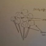
- Face 3d models with pin array uses an array of FSRs to create a point cloud of someone’s face.
- Hug meter (emotion tracker with Kinect) lets you know who needs a hug in a room.
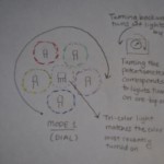
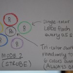
- Lighting based on music input (visualizer)
- Lie detector based on voice. Arduino does FFT to isolate irregularities in the person’s voice.
- Underground meal swipes market uses an Arduino and a magnetic card reader to reprogram a prox.
- Covert t-shirts pay attention to vibrations and secret gestures to convey information without speaking.
- Fingerprint replication uses an Arduino and a fingerprint scanner to create a fingerprint mesh for replication.
- Sound detecting system that generates mood/ambiance music to rhythm of sex (or any other rhythmic activity)
- Using a Kinect or raspberry pis to track a speaker on stage (example application — spotlight).
- Using a Kinect to scan someone’s BMI, offering customized health information (ex. safe amount of alcohol one individual could imbibe)
- Leap motion controller virtual keyboard that allows typing on any surface.
- Kinect a cappella system which uses spatial data and skeleton data to allow a person to create synthesized songs by themselves (or with others!), recording multiple music tracks and overlaying them.
PART 2:
- A Cappella Solo Live (#56): Mainstream computer-based electronic instruments and music making machines are still few and far between; there are custom setups designed for particular artists and there are non-programmable, dedicated hardware devices that accomplish much of the same functionality, but they are usually better left to recording engineers instead of performers and certainly are an obstruction while performing on stage in front of a live audience. As several of our group members are musicians and performers, this is also something we are personally quite enthusiastic about. It is also modular enough that a sizeable chunk of functionality can be implemented in this course, and further features can be integrated later.
- Alternative: Triangulation of sounds using multiple Raspberry Pis and sound sensors (#19): Initially, the idea was developed to have real-world significant applications, like triangulating gunshots in warzones or other critical sounds throughout a city, room, building, etc. It’s really interesting because, even though the technology already exists, using raspberry pis would effectively make it the cheapest available technology of its kind. This would allow the product to be used in a wide-range of applications previously not possible!
PART 3:
- Target audience: professional musicians, amateur musicians, “Youtube artists,” and other Kinect owners who want a live, interactive synthesizer and looper for experimentation. With an unobtrusive, floor-mounted Kinect connected to a small laptop (that can be used as a monitoring screen) in front of the user, the system can be used in concert halls as a live performance tool. Alternatively, the same system set up in a living room (perhaps connected to a home theatre PC) allows for an entertaining quasi-game, and an easy way to record and create music for publishing online. This could gain traction among the many talented Youtube artists who incorporate various technologies to create great covers and original music.
- Problem description/context: Looper-synthesizers (usually used with guitars or synth tracks) exist in several forms today, including iOS apps and hardware devices, but the iOS take on loopers (VoiceJam) is very much an experimentational and maybe recording tool instead of a live performance capable setup, and hardware-based loopers are specialized equipment that present a pretty steep learning curve for those not well versed in how they work; they are also quite expensive. However, they are great fun, and we expect that many people would love to have the functionality if presented in an intuitive way that requires little specialized equipment. Thus the barrier to entry is lowered by using the Kinect + computer based approach, and the experience of interacting with the machine is less a distraction from the performance and more an integral part of the choreography itself.
- Appropriate technology: The modularity and flexibility of this system means that it can be used to perform live (laptop + Kinect), practice and experiment in a living room (HTPC + TV + Kinect), or any of a variety of other configurations. Kinect is small and highly portable, making it trivially easy to set up at performance venues (especially compared to things like speakers, stage extensions, etc). Implementing all of the backend logic in software allows us to add functionality as we choose, and the Kinect is a relatively inexpensive I/O device that is also perfectly suited to the job; it can track skeleton movements as well as z-axis movement for easier and more precise gesture analysis, which we wouldn’t get from a normal camera. Finally, we can include Arduino-powered elements that also interface with the same computer running the backend software, which would allow us to add functionality that the Kinect can’t handle, such as individual finger flex movements.
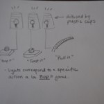
Possible sketches:
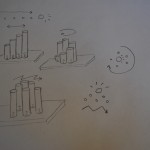
- Kinect vision — what the kinect sees, multiple areas of the screen correspond to multiple voices/modulations.
- One person can sing with themselves; the system records the sounds at each section of the screen and modulates based on the body movements, overlaying each section — jumping, kicking, arm movements, different voice sounds, more dancing and singing