
i. Group: Philip Oasis, Gene Merewether, Alice Fuller, Rodrigo Menezes
ii. We built a color mixer, in which the user turns a potentiometer to adjust the brightness of red, green, and blue LEDs, and then observes the mixed output of the three hues on a single RGB LED. The purpose for the user is to observe how RGB colors are mixed, as well as a fun way to try making new colors. The tissue paper diffuser is meant to spread out the light and make it easier to view. We feel that it is successful in achieving these goals, and that the interface is relatively easy to understand and operate. We enjoyed using the final product and trying to make interesting colors. We might have liked to use more LED’s to make the panel brighter and easier to see.
iii. Sketches of possible designs
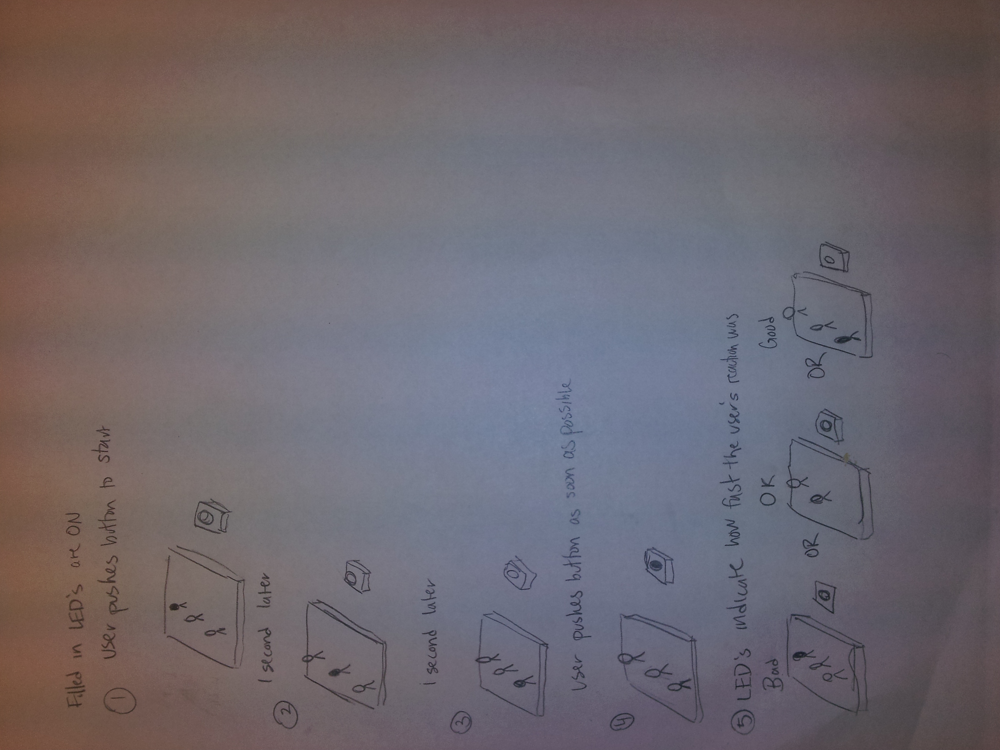
A reaction game where the user tries to hit the push button after the final LED is lit.

A memory game in which the user uses a button to select the LED which was lit a certain number of lights ago.

A color mixer in which the user selects brightness of red, green, and blue LED’s and then observes the combination of those hues.
iv. Video of the system in action
http://www.youtube.com/watch?v=RQmMFz5ngmM
v. Parts list
- (1) Red LED
- (1) Green LED
- (1) Blue LED
- (1) Tricolor LED
- (1) 10k trimpot
- (4) 330 ohm resistor
- (2) Breadboard
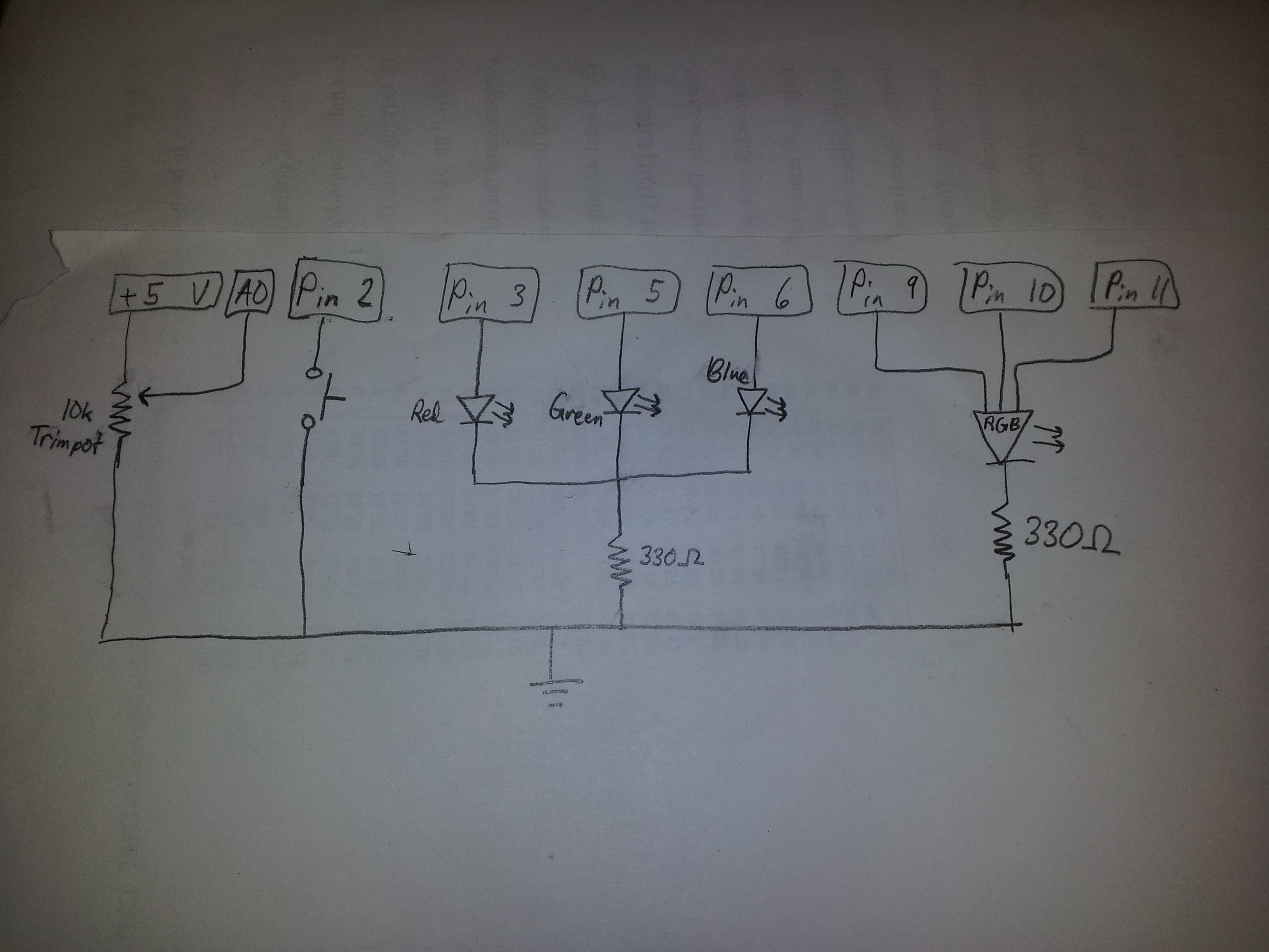
vi. Instructions to recreate design
- Connect potentiometer to analog pin A0, powered by 5v
- Connect push button to digital pin 2, powered by 5v, with a 330Ω resistor.
- Connect red, green, and blue LED’s to digital pins 3, 5, and 6 (respectively), all powered by 5v and each with a 330Ω resistor.
- Connect the rgb LED to digital pins 9, 10, and 11, again powered by 5v, and with 330Ω resistors.
- (optional) Cover the LED’s with a tissue paper diffuser
vii. Source code
const int sensorPin = 0;
const int buttonPin = 2;
const int redPin = 3;
const int greenPin = 5;
const int bluePin = 6;
const int ledRedPin = 9;
const int ledGreenPin = 10;
const int ledBluePin = 11;

const int RED_STATE = 0;
const int GREEN_STATE = 1;
onst int BLUE_STATE = 2;

int prevButtonState;
int systemState;
int redValue;
int greenValue;
int blueValue;
void setup() {
    Serial.begin(9600);
    pinMode(buttonPin, INPUT);
    pinMode(redPin, OUTPUT);
    pinMode(bluePin, OUTPUT);
    pinMode(greenPin, OUTPUT);
    pinMode(ledRedPin, OUTPUT);
    pinMode(ledGreenPin, OUTPUT);
    pinMode(ledBluePin, OUTPUT);

    prevButtonState = HIGH;
    systemState = RED_STATE;
    redValue = 0;
    greenValue = 0;
    blueValue = 0;
}

void loop() {
    int buttonState = digitalRead(buttonPin);
    int sensorValue = analogRead(sensorPin)/4;
    Serial.println(sensorValue);

    if (buttonState == HIGH && prevButtonState == LOW)
    {
        systemState = systemState + 1;
        if (systemState == 3)
        {
            systemState = 0;
        }

    }
    prevButtonState = buttonState;
    switch (systemState)
    {
         case RED_STATE:
             redValue = sensorValue;
             analogWrite(redPin, redValue);
             analogWrite(greenPin, 0);
             analogWrite(bluePin, 0);
             break;
         case GREEN_STATE:
             greenValue = sensorValue;
             analogWrite(redPin, 0);
             analogWrite(greenPin, greenValue);
             analogWrite(bluePin, 0);
             break;
         case BLUE_STATE:
             blueValue = sensorValue;
             analogWrite(redPin, 0);
             analogWrite(greenPin, 0);
             analogWrite(bluePin, blueValue);
             break;
         }

analogWrite(ledRedPin, redValue);
analogWrite(ledGreenPin, greenValue);
analogWrite(ledBluePin, blueValue);
}