
We designed an RGB version of the ever-popular Whack-a-Mole game using a single multicolor LED, some buttons, and good old Arduino. We wanted to create something entertaining and interactive, that similarly allowed us to explore coding on the Arduino. At first, we envisioned a game with multiple LED’s, but then decided that playing the game in response to different colors in a single light was much more interesting than responding to the turning on or off of lights. Our second revision imagined the multicolor LED starting out as fully lit (white light), and then having components of the light drop out with the player having to press buttons to restore those color components. We liked the dual challenge both of reacting quickly and having to determine which color component was missing, but when playtesting we found that this latter aspect of the challenge was more frustrating than enjoyable for the player. Our final version lights up the LED with one of the three colors behind the diffusion screen and rapidly begins to dim. If the player either fails to respond in time or presses the wrong button, the light will go white, signaling GAME OVER! We are overall quite happy with how the game turned out, and how it helped us play around with the Arduino. The game is fun and completely customizable in just about every parameter. However, we had very few materials with which to construct the physical exterior of the game, so the prototype itself is somewhat of an eyesore.
Team Members: Joseph Bolling, Evan Strasnick, Aleksey Boyko, Jacob Simon
List of Parts:
- Arduino Uno
- Pushbutton style switches (3)
- Tri-color RGB LED
- 330Ω resistors (3)
- Wire jumpers
- Prototyping Breadboards (2)
- Cardboard
- Scotch tape
Instructions:
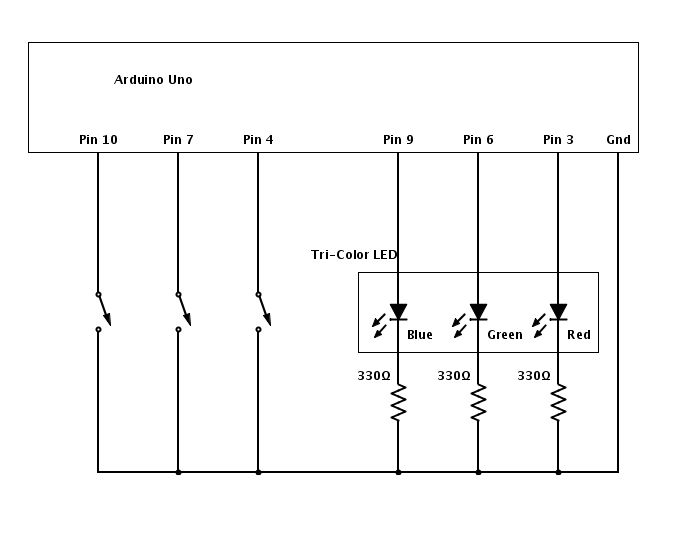
To create your own RGB Whack-a-Mole game, take a look at the circuit included above as a reference. For the switches, use basic push-buttons. Note that we chose to place our buttons on a separate breadboard from our tri-color LED, so that we would have a rudimentary controller and output device setup. Connect the button that you’d like to correspond to the red color to pin 4 of the Arduino, the button that you’d like to use for blue to pin 7, and the button that you’d like to use for green to pin 10. The red, green, and blue led leads should connect to pins 3, 6, and 9, respectively.
Label your buttons with the color they control, and make a cover for your LED so that the wiring is protected and hidden. We used simple cardboard and some scotch-tape to make a window for our LED. Then, upload our code to your Arduino and have fun!
Diagrams:
RGB Whack-a-Mole Circuit — This is the idea we implemented.
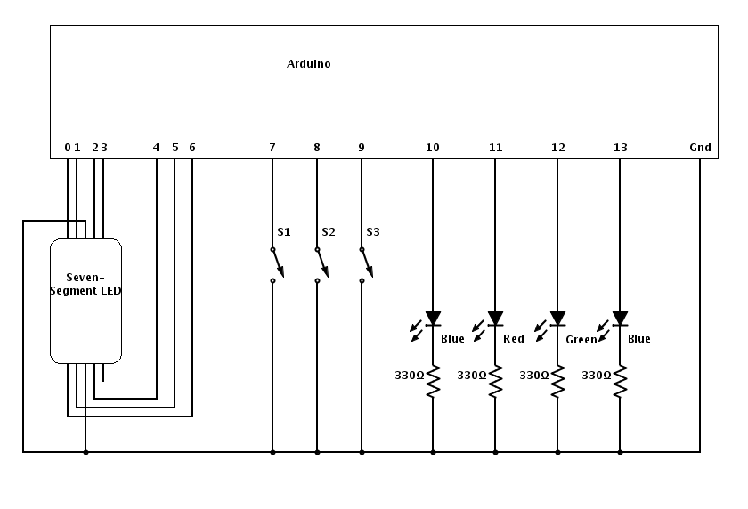
Binary Calculator Circuit — This would allow the user to perform simple arithmetic.
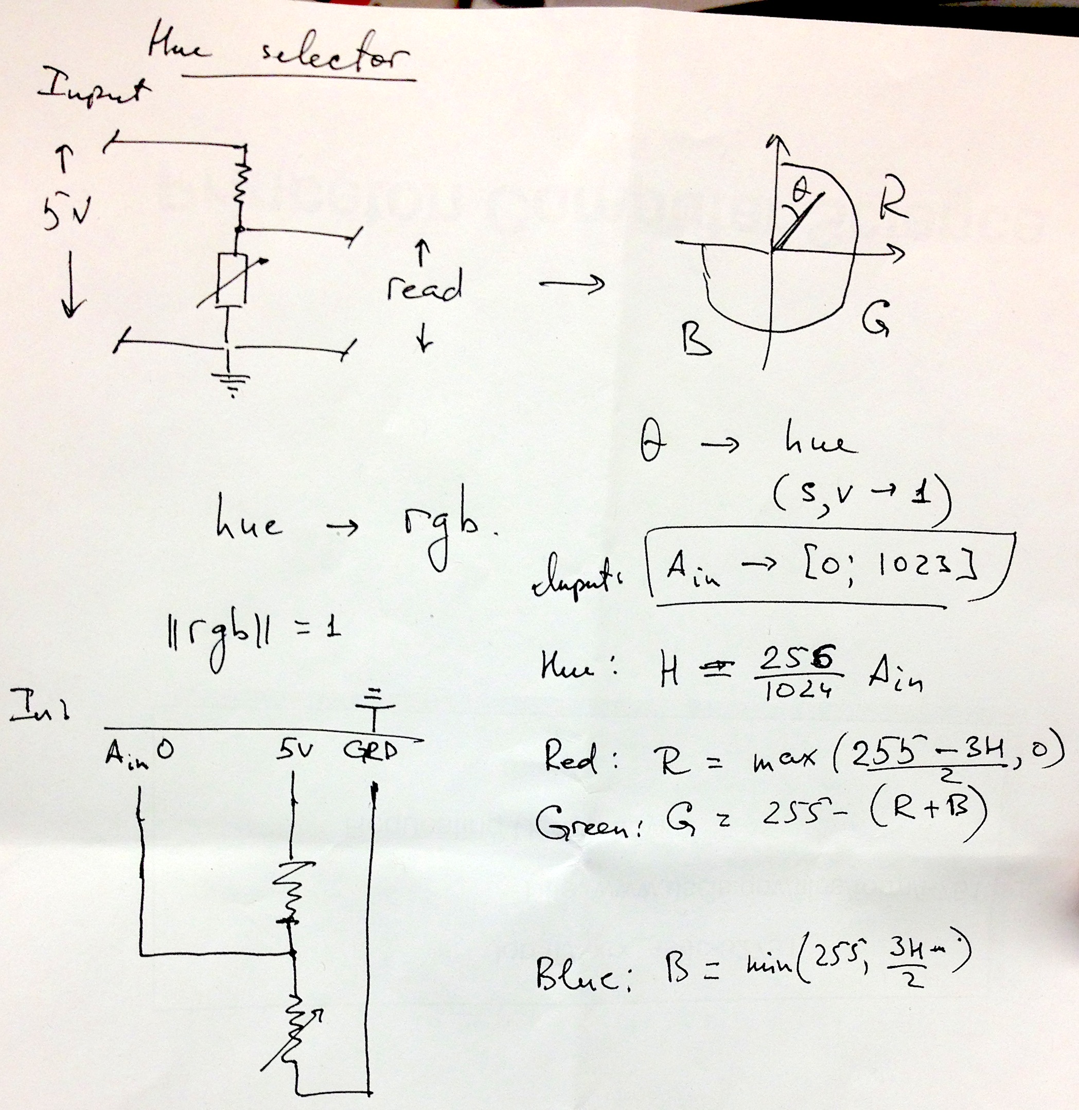
Color Selector Circuit — This would allow the user to create any color by selecting its RGB components.
Arduino Program:
// :::::::::::::::::::::::
// Lab 0
// COS436 / ELE469
// Trichromatic Whack-a-Mole / Color Blindness Reflex Test
// Group participants: jbolling, jasimon, estrasni, aboyko
// :::::::::::::::::::::::// :::::::::::::::::::::::
// INPUT PINS
// :::::::::::::::::::::::
int r_but = 4;
int g_but = 7;
int b_but = 10;// :::::::::::::::::::::::
// OUTPUT PINS
// :::::::::::::::::::::::
int r_pin = 3;
int g_pin = 6;
int b_pin = 9;// :::::::::::::::::::::::
// INITIAL COLOR VALUES
// :::::::::::::::::::::::
int r_v = 0;
int g_v = 0;
int b_v = 0;// :::::::::::::::::::::::
// DIMMING PARAMETERS
// :::::::::::::::::::::::
boolean dim_on = false;
int dim_delta = 0;
float dim_factor = 1;
int dim_ch = 0;
int counter = 1;
int score = 0;// :::::::::::::::::::::::
// SETUP FUNCTION
// :::::::::::::::::::::::
void setup() {Serial.begin(9600); // Terminal output
// Input settings
pinMode(r_but, INPUT);
pinMode(g_but, INPUT);
pinMode(b_but, INPUT);digitalWrite(r_but, HIGH);
digitalWrite(g_but, HIGH);
digitalWrite(b_but, HIGH);// Output settings
pinMode(r_pin, OUTPUT);
pinMode(g_pin, OUTPUT);
pinMode(b_pin, OUTPUT);Serial.println(“Set up complete”);
reset_state();
}
// :::::::::::::::::::::::
// MAIN LOOP
// :::::::::::::::::::::::
void loop() {
// If no dimming is happening, try to initiate
if (!dim_on) {
Serial.println(“Dim is not on”);
dim_on = initiate_dimming();
}int io_code = factor_input();
if (dim_on) {
Serial.println(“Dim is on!”);// see if input stops dimming
if (io_code != 0) {
// no user input
dim_more();
} else {
// correct input
counter++;
reset_state();
}
} else {
reset_state();
}// set the diffuser output
analogWrite(r_pin, r_v);
analogWrite(g_pin, g_v);
analogWrite(b_pin, b_v);delay(100);
}void reset_state() {
// Reset color values
r_v = 0;
g_v = 0;
b_v = 0;// Turn dimming off
dim_ch = 0;
dim_on = false;
}boolean initiate_dimming() {
// Choose a random color
dim_ch = random(0, 3);// Turn that color on, full brightness
switch (dim_ch) {
case 0:
analogWrite(r_pin, 255);
r_v = 255;
break;
case 1:
analogWrite(g_pin, 255);
g_v = 255;
break;
case 2:
analogWrite(b_pin, 255);
b_v = 255;
break;
default:
break;
}// New dimming factor
dim_factor = 1.0 – (counter) / 20.0;// Terminal output
Serial.print(“\tDimming channel “);
Serial.print(dim_ch);
Serial.print(” with factor “);
Serial.println(dim_factor);return true;
}int factor_input() {
// read KEY_DOWN events
boolean r_pressed = (digitalRead(r_but) == LOW);
boolean g_pressed = (digitalRead(g_but) == LOW);
boolean b_pressed = (digitalRead(b_but) == LOW);
// encode input with one value
int in_code = (r_pressed?1:0) + (g_pressed?2:0) + (b_pressed?4:0);// if any was down wait until all keys are released
while (r_pressed || g_pressed || b_pressed) {
delay(100);
r_pressed = (digitalRead(r_but) == LOW);
g_pressed = (digitalRead(g_but) == LOW);
b_pressed = (digitalRead(b_but) == LOW);
}// Encode dimming channel in the same way as buttons
int out_code = 0;
if (dim_on)
out_code = 1 << dim_ch;// Difference between input and output
int input_factor = out_code – in_code;// If user’s input doesn’t match correct input…
if (input_factor != 0 && in_code != 0) {
failure(); // Fail and reset
}return input_factor;
}void dim_more() {
if (!dim_on) return;switch(dim_ch) {
case 0:
//r_v += dim_delta;
r_v *= dim_factor;
if (r_v < 10) failure();
break;
case 1:
//g_v += dim_delta;
g_v *= dim_factor;
if (g_v < 10) failure();
break;
case 2:
//b_v += dim_delta;
b_v *= dim_factor;
if (b_v < 10) failure();
break;
default:
break;}
}
void failure() {
digitalWrite(r_pin, 255);
digitalWrite(g_pin, 255);
digitalWrite(b_pin, 255);
Serial.print(“Game over! Score = “);
Serial.print(score);
Serial.println(” Try again…?”);
score = 0;
counter = 1;
dim_on = false;
delay(3000);
}void light_correct() {
score++;
reset_state();
}