
Names:
Farhan Abrol
Dale Markowitz
Collin Stedman
Raymond Zhong
Group Number: 4
Description
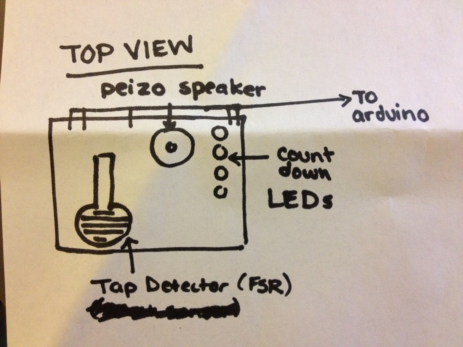
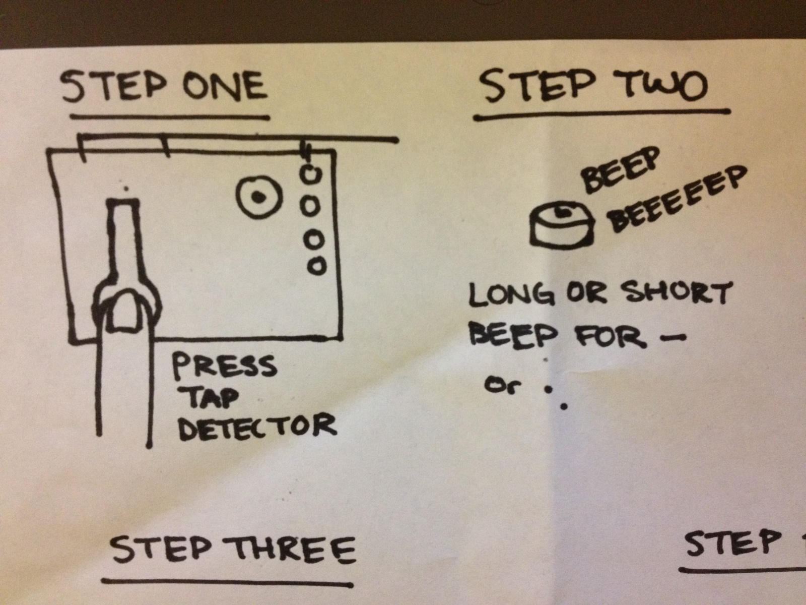
The interface consists of a force sensitive resistor, which the user either taps or holds to send dots or dashes, respectively. A piezo sensor beeps to provide feedback; a short pulse tells the user they have hit the FSR with enough force to trigger it, and a long pulse tells them they have held it down long enough to enter a dash.
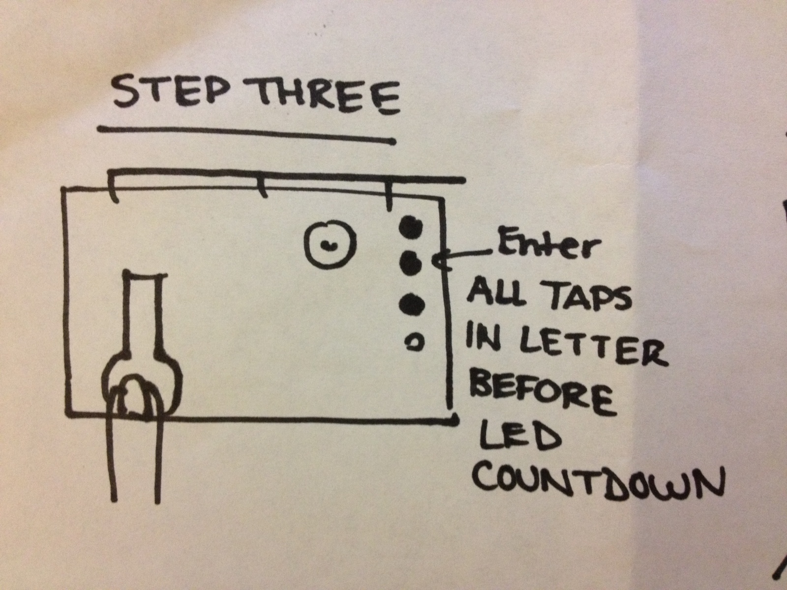
Morse code is tricky to interpret, because not all characters are the same length (i.e. one letter might be a single dot, while another is several dots). In order to get around this, we set up a time interval for which dots or dashes a user enters are considered a single character. This is denoted by four LEDs that “count down” to indicate how long the user has to enter the next dot or dash within the same character.
Assessment
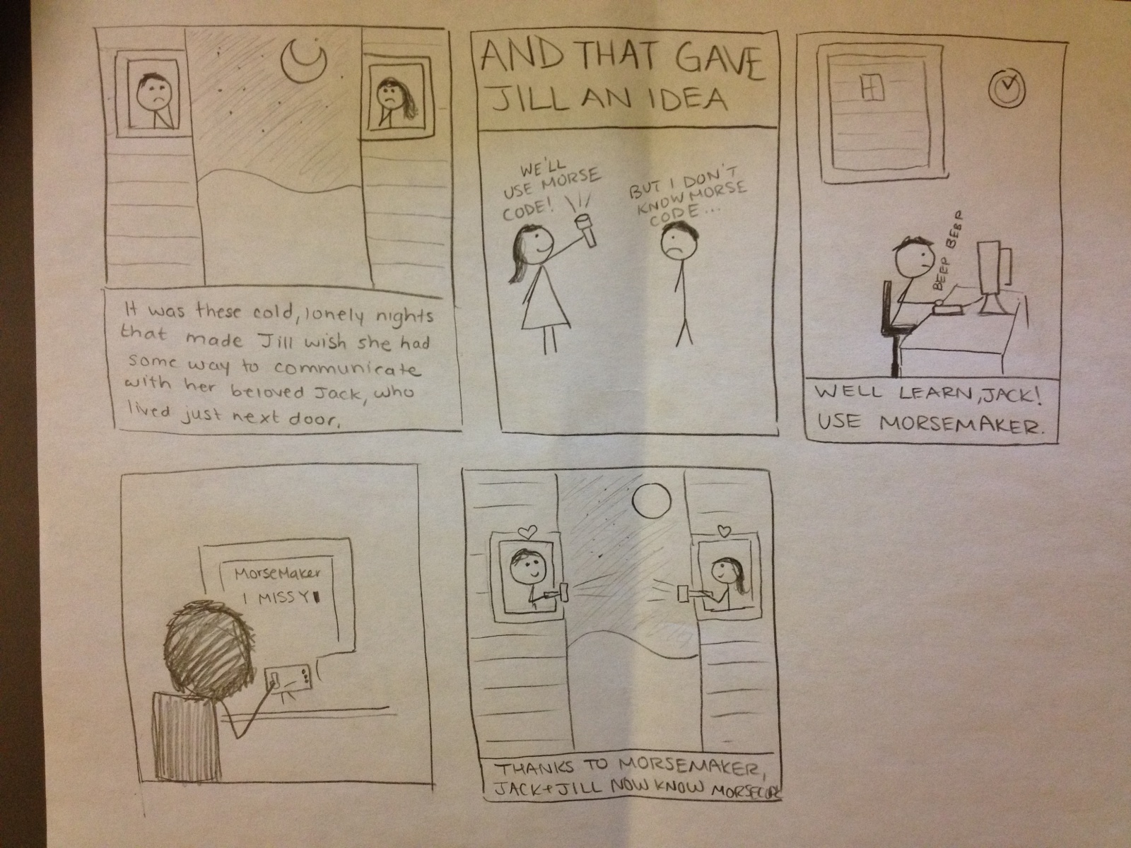
When deciding on what to build for this assignment, our team thought of many options involving interacting with sound through touch. We wanted to build something that was both simple and fun to play with. We went through many ideas involving sound synthesis (especially a drum simulator). Ultimately, we decided on a Morse code interpreter, because we felt it fit well with the supplies we had at hand.
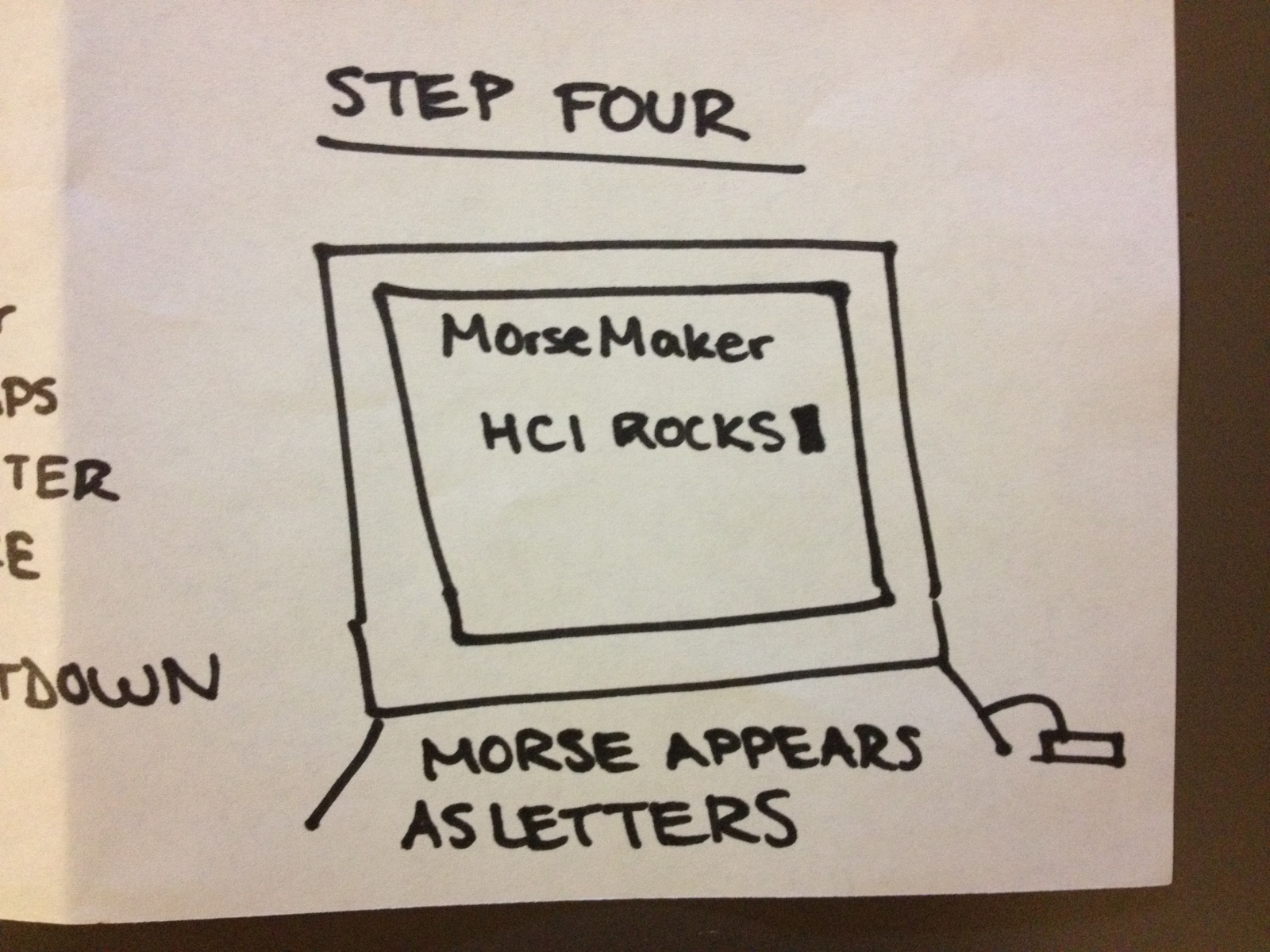
All in all, we were very happy with the way our morse code converter turned out. Although the description sounds complicated, the device is intuitive once you sit down in front of it — and we had fun typing letters on a screen. Perhaps the thing that we are unhappiest with about our device is that it is not super relevant today (what a shame! it’s so fun to play with). It’s a device that might only be appreciated by specialists or true nerds. Whatever those are. 🙂
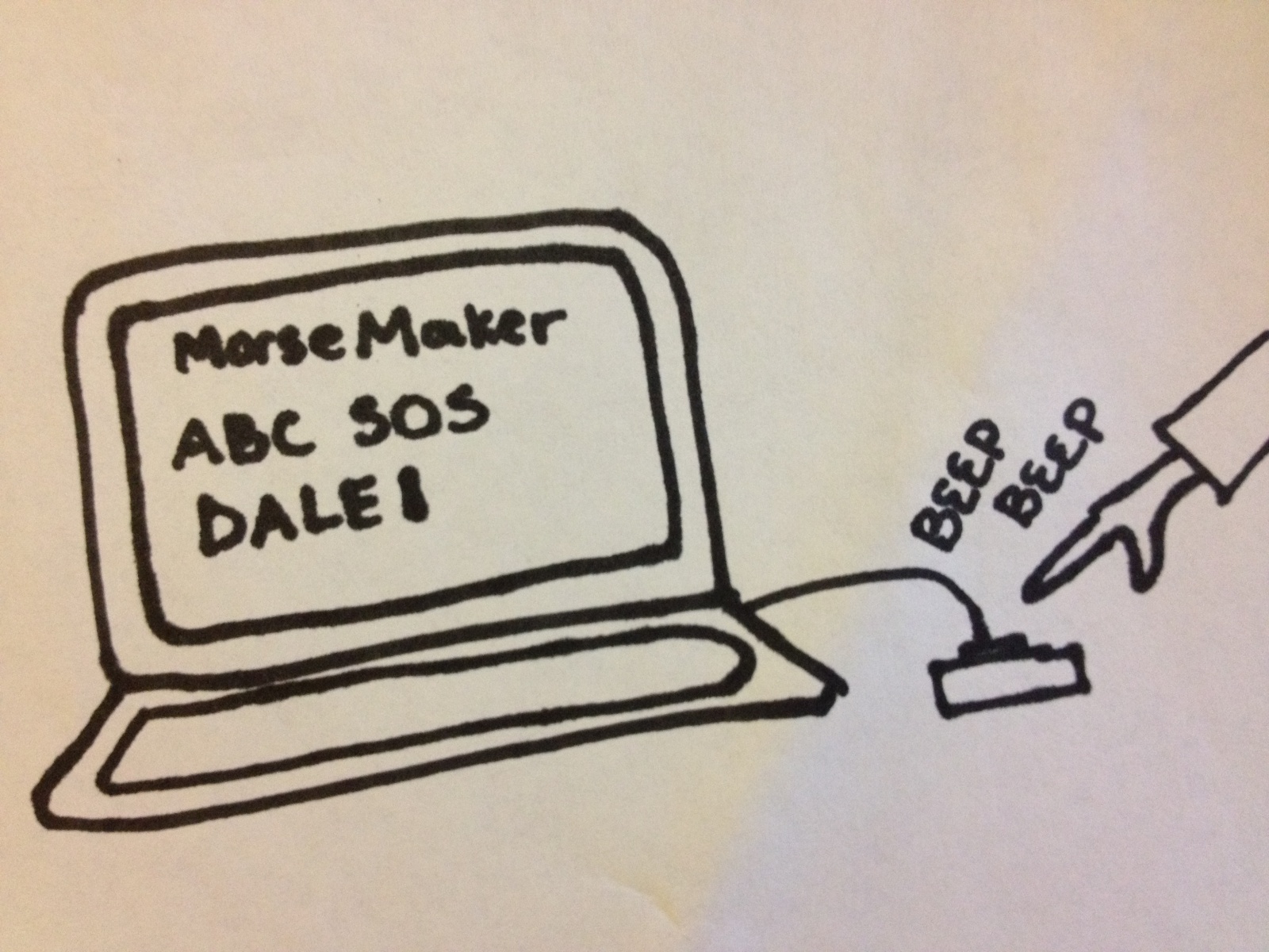
Storyboard
Sketches
Parts List
Breadboard, wire, wire cutter/stripper
Arduino Uno
Force Sensitive Resistor
3 Red LEDS, 1 Yellow LED, and appropriate resistors for 5V source (varies by LED)
Piezo speaker
Computer and source code
Make it yourself!
Only requires everyday prototyping parts!
1. Obtain a force-sensing resistor, an Arduino microcontroller, an electronic breadboard, as well as several LEDs and appropriate resistors for each component.
2. Attach the force-sensing resistor to the center of the breadboard, in such a way that it can be taped onto the edge of the top of the breadboard.
3. Connect the FSR to the analog sensing port of the Arduino, using a pull-down resistor connected to ground.
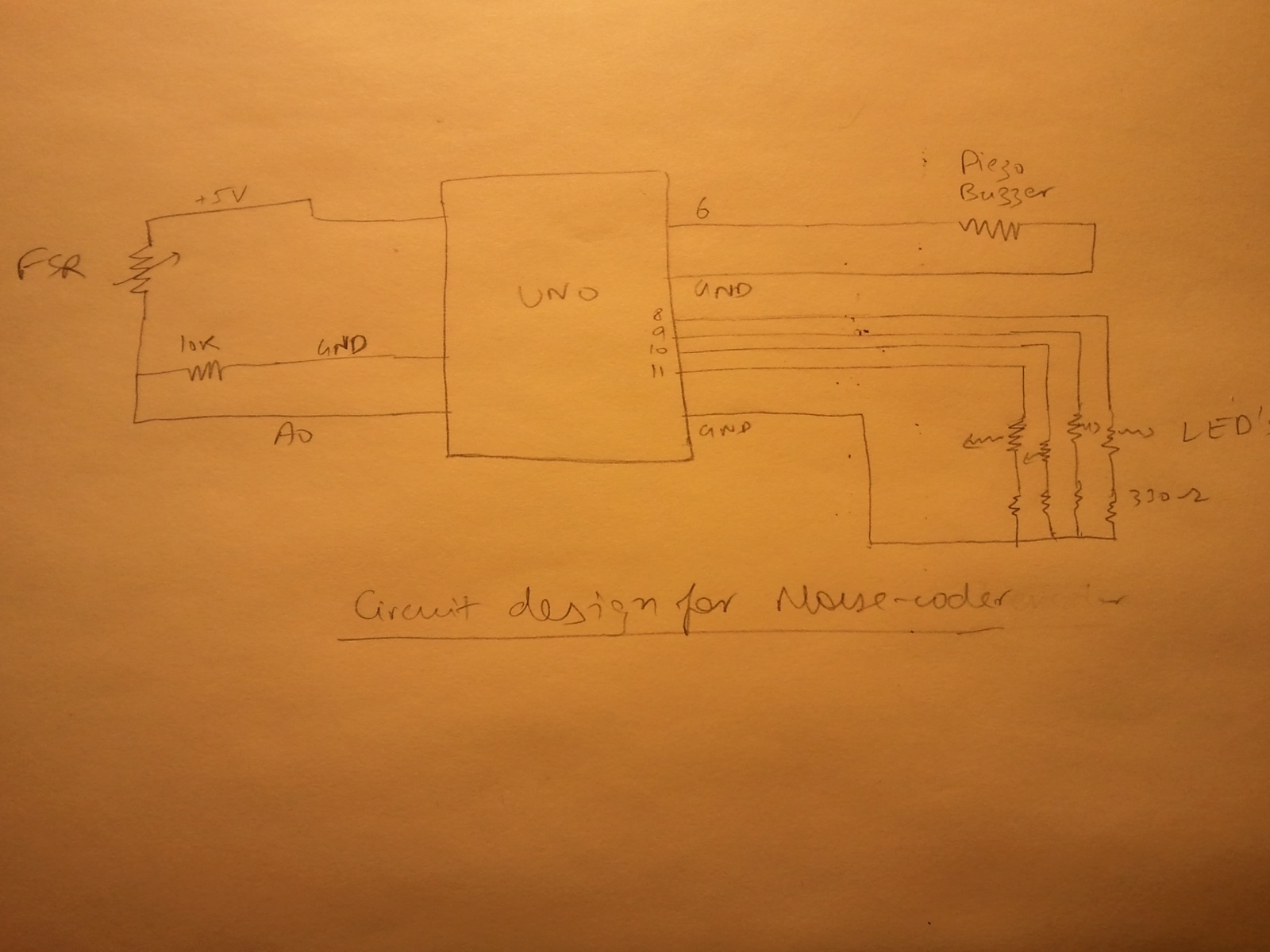
3. On the opposite side of the breadboard, attach a row of LEDs, connecting them to digital output pins on the Arduino through 330 ohm resistors.
4. Tape the FSR onto the breadboard so that it can be easily tapped or held with a finger.
5. Set the FSR pin, the first LED pin, and the number of LEDs used in the Arduino program.
6. Download the Arduino program, and run the keyboard filter on your computer.
Congrats, you can now type in Morse code!
Arduino Code
/* FSR simple testing sketch.

Connect one end of FSR to power, the other end to Analog 0.
Then connect one end of a 10K resistor from Analog 0 to ground
*/

int fsrPin = 0;     // the FSR and 10K pulldown are connected to a0
int fsrThreshold = 20;
int fsrReading;     // the analog reading from the FSR resistor divider
int delayTime = 10;
int buzzerPin = 6;

// number of delay loops for each symbol
int dotLength = 1;
int dashLength = 20; // 200ms
int letterSepLength = 100; // 1000ms
int pauseLength;
int tapLength;

// length of tones emitted for each button press
int dotToneLength = 30;
int dashToneLength = 100;

// LED status display
int firstLEDpin = 8;
int numLEDpins = 5;

void setup(void) {
  Serial.begin(9600);
}

void sendLetterEnd() {
  Serial.println("2");
}

void sendDot() {
  Serial.println("0");
  tone(buzzerPin, 440);
  delay(dotToneLength);
  noTone(buzzerPin);
}

void sendDash() {
  Serial.println("1");
  tone(buzzerPin, 1000);
  delay(dashToneLength);
  noTone(buzzerPin);
}

void lightLEDs() {
  for (int i = 0; i < numLEDpins; i++) {
    digitalWrite(firstLEDpin + i, 1);
  }
}

void dimLEDs() {
  for (int i = 0; i < numLEDpins; i++) {     if (pauseLength > i*letterSepLength/numLEDpins) {
      digitalWrite(firstLEDpin + i, 0);
    }
  }
}

void beep() {
}

void loop(void) {
  fsrReading = analogRead(fsrPin);

  if (fsrReading < fsrThreshold) {     if (dashLength > tapLength && tapLength > dotLength) {
      sendDot();
      lightLEDs();
    }
    if (pauseLength == letterSepLength) {
      sendLetterEnd();
    }
    dimLEDs();
    tapLength = 0;
    pauseLength++;
  } else {
    if (tapLength == dashLength) {
      sendDash();
      lightLEDs();
    }
    pauseLength = 0;
    tapLength++;
  }
  //Serial.print("Analog reading = ");
  //Serial.println(fsrReading);     // the raw analog reading
    delay(delayTime);
}
Processing Code:
github.com/dalequark/morsecode
[kaltura-widget uiconfid=”1727958″ entryid=”0_0e1153da” width=”400″ height=”360″ addpermission=”” editpermission=”” /]