
Team Deep Thought (Group 25):
Vivian Qu
Neil Chatterjee
Alan Thorne
Harvest Zhang
We built a device that mimics a theremin, controlled using a light sensor and touch sensitive slider (softpot). The goal of the device is to be a fun, interactive way to play music using the sensors. This device also could conceivably be used to teach young students about the physics of sound waves, since our visualizer shows the actual wave form changing in proportion to the user’s actions! One issue we had is that we needed to keep a finger on the softpot at all times or else there were spikes in the sound because the readings need to stabilize. This would be an aspect we would want to fix to streamline the experience. Future improvements could include adding buttons to change the tone of the sound and figure out how to control two different wave forms simultaneously. Otherwise, the device successfully works and allows the user to control the graphic sine wave to create different sounds.
I. Photos & Videos:
Pulse Monitor — Uses a light sensor to detect the changes in light filtered through the skin, detecting the heartbeat. Emits sound from the buzzer to match the heartbeat.
-
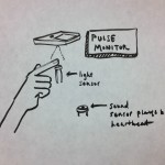
- Pulse Monitor
-
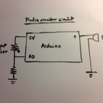
- Pulse Monitor Circuit
Precise Clicker — The device uses a flex sensor as a discreet clicker for presentations.
-
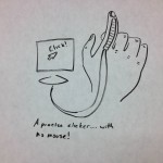
- Precise Clicker
-
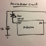
- Precise Clicker Circuit
Bop-It — A fun interactive game based on the “Bop-It” games, where LED lights signal which sensor (Flex/FSR/Potentiometer) to manipulate.
-
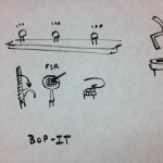
- Bop-It
-
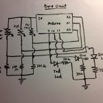
- Bop-It Circuit
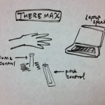
Theremax — Uses the softpot and light sensor to control the frequency and amplitude of the sound wave.
-
- Theremax
-
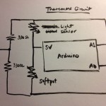
- Theremax Circuit
We chose to implement the Theremax idea, coming up with the following storyboard for why a user would want to interact with the device.

Here’s a video of our device at work:
The touch sensitive slider (softpot) controls the frequency and the light sensor controls the amplitude. Sliding down on the slider increases the frequency, and covering the light sensor (less light input) reduces the frequency.
II. Parts Used
- Arduino Uno x1
- Photocell x1
- Softpot x1
- 330 ohm resistors x2
- Breadboard
- Wires
III. Setup
Connect the middle lead of the softpot to analog input (we used A0) and the leftmost lead to 5V and the third through a 330 ohm resistor to ground. Connect the left leg of the photocell to 5V and the other leg is connected to both analog input (we used A1) and through a resistor to ground. Download the source code, using Arduino and Processing. Upload the code to the Arduino and voila!
IV. Source Code
ARDUINO CODE
// Lab 1: Theremax
// Arduino code to read user input from softpot and thermoresistor.

// Frequency
int freq;
// Amplitude
int ampl;
// Receiving input from analog ports 0 and 1.
int thermo = 0;
int softpot = 1;

void setup(void) {
// Send input data to Processing via the Serial monitor.
Serial.begin(9600);
}

void loop(void) {
  // Read from input.
  ampl = analogRead(thermo);
  freq = analogRead(softpot);

  ampl = map(ampl, 0, 260, 0, 100);
  freq = map(freq, 0, 500, 0, 100);

  // Send data to Processing.
  Serial.write(ampl);
  Serial.write(freq);

  delay(500);
}
ARDUINO CODE
// Lab 1: Theremax
// Processing code to output sound and graphically show the oscillator.

import ddf.minim.*;
import ddf.minim.signals.*;
import processing.serial.*;
Serial port;
Minim minim;
AudioOutput out;
SineWave sine;
int volume;
int slider;

void setup()
{
  size(512, 200, P3D);
  port = new Serial(this, Serial.list()[0], 9600);
  minim = new Minim(this);
  // Get a line out from Minim, default bufferSize is 1024, default sample rate is 44100, bit depth is 16
  out = minim.getLineOut(Minim.STEREO);
  // Create a sine wave Oscillator, set to 440 Hz, at 0.5 amplitude, sample rate from line out
  sine = new SineWave(440, 0.9, out.sampleRate());
  // Set the portamento speed on the oscillator to 200 milliseconds
  sine.portamento(200);
  // Add the oscillator to the line out
  out.addSignal(sine);
  volume = 0;
  slider = 0;
}

void draw()
{
  // Compensate for variable readings at the extremes.
  if (port.available() > 0 )
  {
    volume = port.read();
    int temp = port.read();
    if (temp >= 0 )
    slider = temp;
  }
  float freq = map(slider, 0, 100, 60, 1500);
  // Change the frequency of the wave.
  sine.setFreq(freq);
  float volout = map(volume, 0, 100, 0, 1);
  // Change the amplitude of the wave.
  sine.setAmp(volout);
  background(0);
  stroke(255);
  // Draw the waveforms
  for(int i = 0; i < out.bufferSize() - 1; i++)
  {
    float x1 = map(i, 0, out.bufferSize(), 0, width);
    float x2 = map(i+1, 0, out.bufferSize(), 0, width);
    line(x1, 50 + out.left.get(i)*50, x2, 50 + out.left.get(i+1)*50);
    line(x1, 150 + out.right.get(i)*50, x2, 150 + out.right.get(i+1)*50);
  }
}
The Processing code relies on the Minim library and is based on the Sine Wave Signal code found here.