
Krithin Sitaram (krithin@)
Amy Zhou (amyzhou@)
Daniel Chyan (dchyan@)
Jonathan Neilan (jneilan@)
Thomas Truongchau (ttruongc@)
Expressive Cyborg Shades:
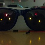
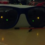
We positioned four LED lights on each lens and mimicked four emotions: evil (\ /), happy (^ ^), surprised (o o), and sleepy (v v). The emotions depend on ambient light (i.e. Bright ambient light evokes “happy”, a lack of ambient light evokes “evil” or “sleepy”). When the cyborg is turned on, it is happy. When ambient light is below a certain threshold, the cyborg becomes evil. As soon as light strikes above the threshold, the cyborg becomes surprised for two seconds, and then gets happy. We were inspired by evil animated furbies that have scary eyes. We also wanted to mimic human emotions in response to darkness and light, in a way in which the emotion matched the level of ambient light. Overall, we believe the project was a resounding success! Our cyborg responds well to varying ambient light levels. However, it is currently not wearable. What we like the most in our final result is that it responds and interacts with us well, inspiring great joy in us all. In the future, we will need more LED’s to get more expressive emotions and more variety of emotions. We can also use more compact circuitry using transparent circuit boards.
Photos/Videos & Captions
-
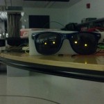
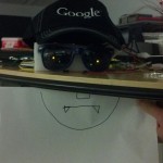
- Expressive Cyborg Glasses
-
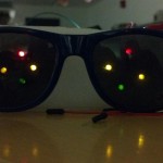
- Surprised Mode
-
- Happy Mode
-
- Evil Mode
-
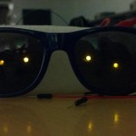
- Sleeping Mode
-

- Styrofoam board
-
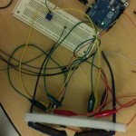
- Wiring
-
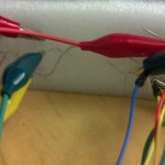
- More wiring
-
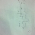
- Final Design
-

- Early Design
-
- Design for a Memory Game
-
- Design for Dancing Lights
Parts Used:
– Arduino
– 1 photocell
– 8 LED lights
– 1 100 Ohm resistor
– 1 variable resistor
– 1 long grounding wire
– 5 alligator clips
– Wires
– Styrofoam
– Sunglasses
Instructions for Recreating:
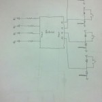
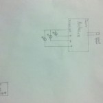
We first cut the styrofoam to fit behind the glasses, and poked the legs of the LEDs through. All the LEDs were connected in parallel. The ground pins of the LEDs were bent to make them flush with the surface of the styrofoam, and a single bare copper ground wire was hooked around them all and connected to a ground pin on the Arduino. Then the other pins of the LEDs were hooked up to the Arduino in pairs, with one light from each eye connected to a single analog output pin on the Arduino as indicated in the diagram.
The light sensor was connected in series with a fixed 100 Ohm resistor and an appropriately tuned potentiometer, and the 3.3V output of the Arduino was set across these. A tap was connected to measure the potential difference across the light sensor at analog input A0 of the Arduino.
Source Code:
/***
Pin numbers for left and right eye

   3      3
 5   6   6  5
   9      9
*/

int lightsensor = 0;
int threshold = 150;
int surprisedcounter = 0;
int surprisedlength = 2;
int sleepiness = 0;
int sleepaftertime = 10;

void setup() {
  Serial.begin(9600);
  happy();
}

void happy() {
  analogWrite(3, HIGH);
  analogWrite(6, HIGH);
  analogWrite(5, HIGH);
  analogWrite(9, LOW);
}
void evil() {
  analogWrite(5, HIGH);
  analogWrite(9, HIGH);
  analogWrite(3, LOW);
  analogWrite(6, LOW);
}
void surprised() {
  for (int i = 1; i < 14; i++) {
    analogWrite(i, HIGH);
  }
}
void sleep() {
  analogWrite(9, LOW);
  analogWrite(6, HIGH);
  analogWrite(5, HIGH);
  analogWrite(3, LOW);
}

void loop() {
  Serial.println(analogRead(lightsensor));
  if (analogRead(lightsensor) < threshold) {
    sleepiness = 0;
    if (surprisedcounter > 0) {
      surprised();
      surprisedcounter--;
    } else {
      happy();
    }
  } else {
    if (sleepiness > sleepaftertime) {
      sleep();
    } else {
      sleepiness++;
      surprisedcounter = surprisedlength;
      evil();
    }
  }
  delay(1000);
}