P3: Lab Group 14

a) Group Information: Group #14, Team Chewbacca

b) Group Members

Karena Cai (kcai@) – in charge of designing the paper prototype
Jean Choi (jeanchoi@) – in charge of designing the paper prototype
Stephen Cognetta (cognetta@) – in charge of writing about the paper prototype
Eugene Lee (eugenel@) – in charge of writing the mission statement and brainstorming ideas for the paper prototype

c) Mission Statement

The mission of this project is to create an integrated system that achieves the goal of helping our target users take care of their dog in a non-intrusive and intuitive way. The final system should be almost ready for consumer use, excepting crucial physical limitations such as size and durability.  The purpose of the system is to aid busy dog-owners who are concerned about their dogs’ health but who must often spend time away from their household due to business, vacation, etc. Our system does so by giving the user helpful information about their dog, even when they are away from home. It would help busy pet-owners keep their dogs healthy and happy and give them greater peace of mind.  By helping owners effectively care for their pets, it might even reduce the number of pets sent to the pound, where they are often euthanized.  In our first evaluation of the prototype system, we hope to learn about what users consider the most crucial part of the system. In addition, we will learn to what extent the information about their dog should be passively recorded or actively notified to the user. Finally, we will try to uncover as many flaws with our current design as possible at this early step. This will prevent us from using our limited time on a feature that does not actually provide any benefit to the user.

d) Description of prototype

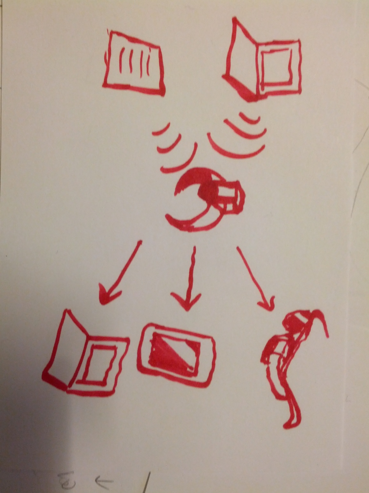
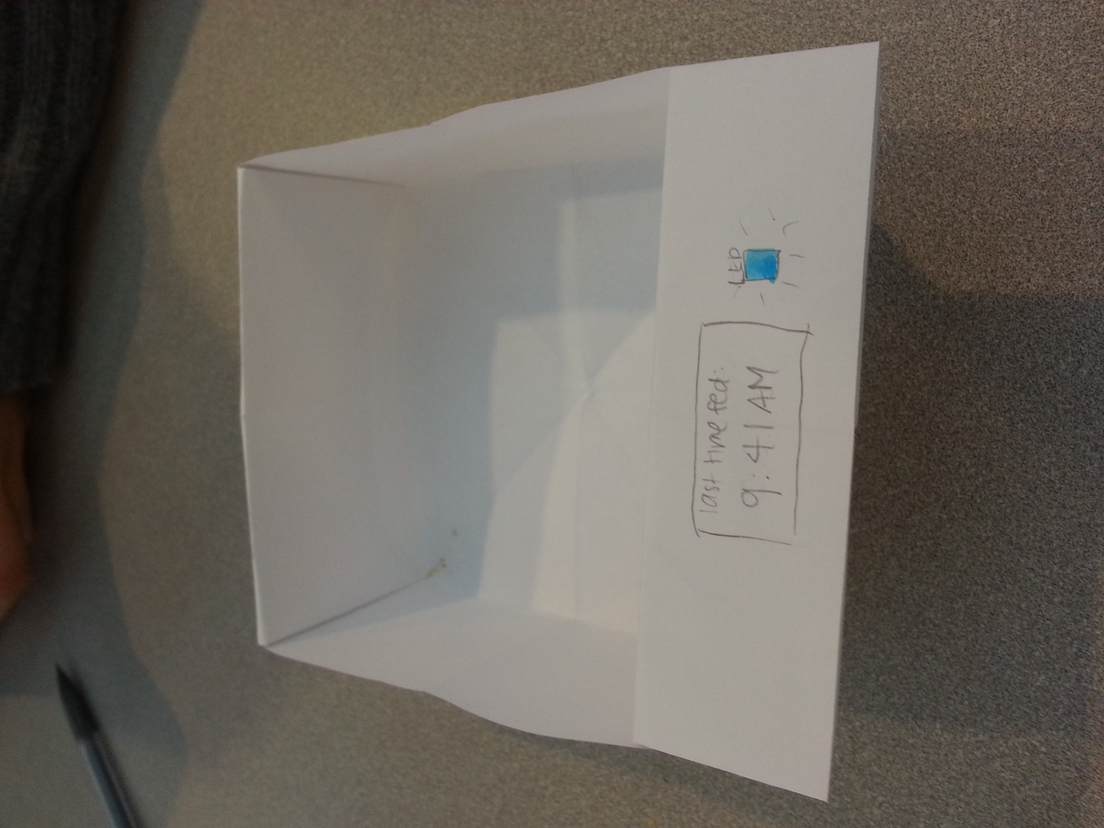
Our prototype includes three components: a paper prototype of the mobile application, a prototype of the dog bowl, and a prototype of the dog collar.  The mobile application includes the home screen and screens for tracking the dog’s food intake, tracking its activity level, and creating a document that includes all pertinent data (that can be sent to a vet).  The dog bowl includes an “LED” and a “screen” that shows the time the bowl was last filled.  The collar includes an “LED”.

20130329_162734

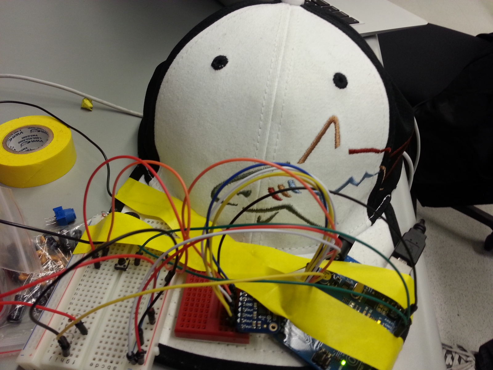
A prototype for the dog bowl (Task 1)

20130329_162527

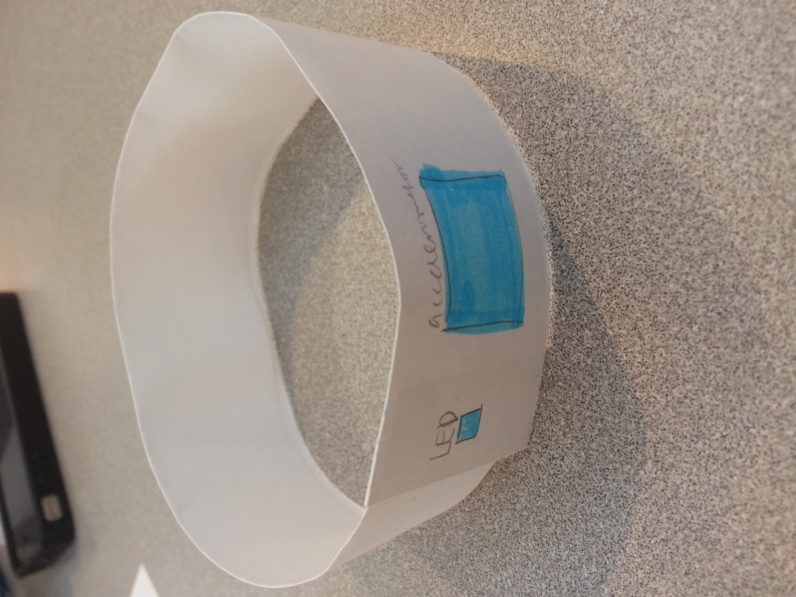
Prototype for the dog collar (Task 2)

photo (2)

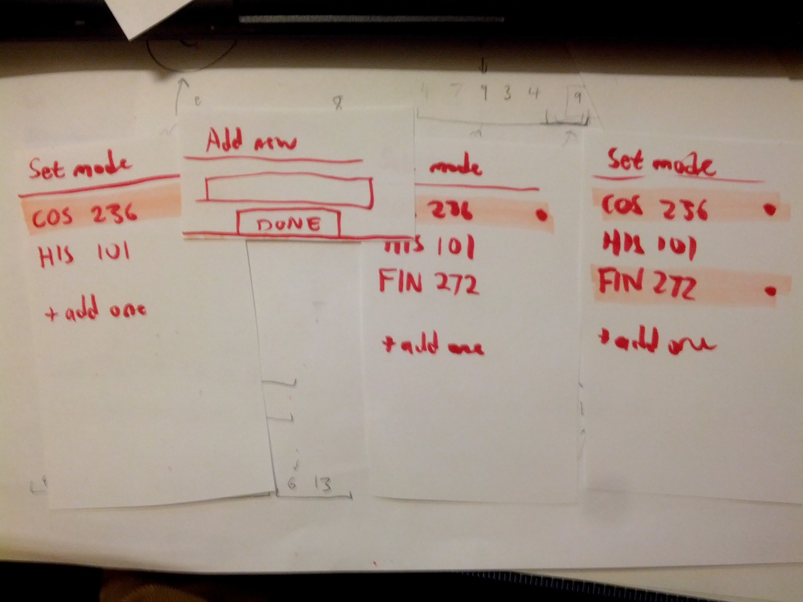
Notification set-up for the application

20130329_162806

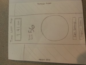
Main page for the app, where it shows exercise, diet, time since last fed, a picture of the dog (would go in the circle), edit settings, and exporting the data.

20130329_162952

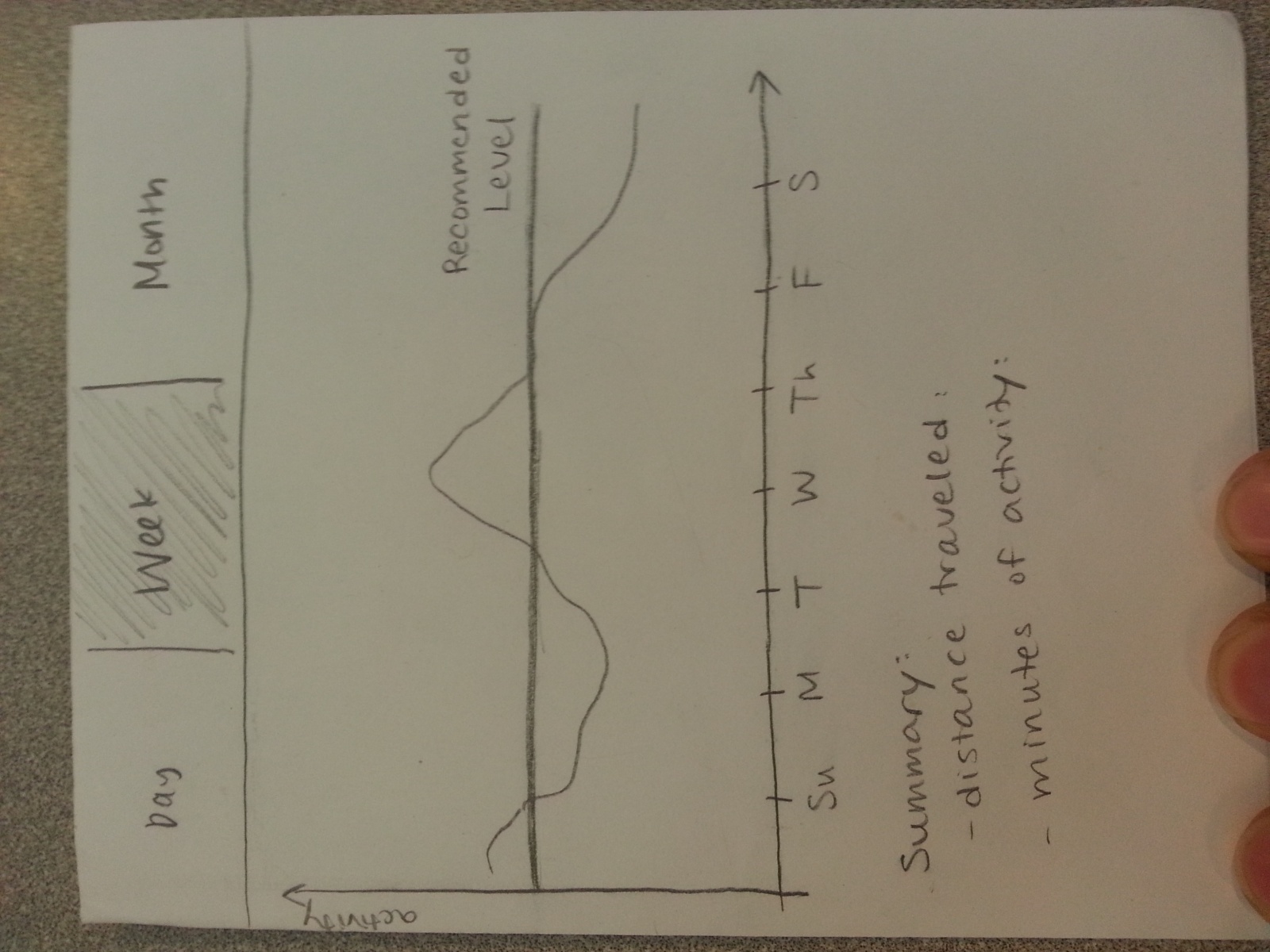
Exercise information for the dog, shown over a day, week, or a month. (Task 2)

20130329_162852

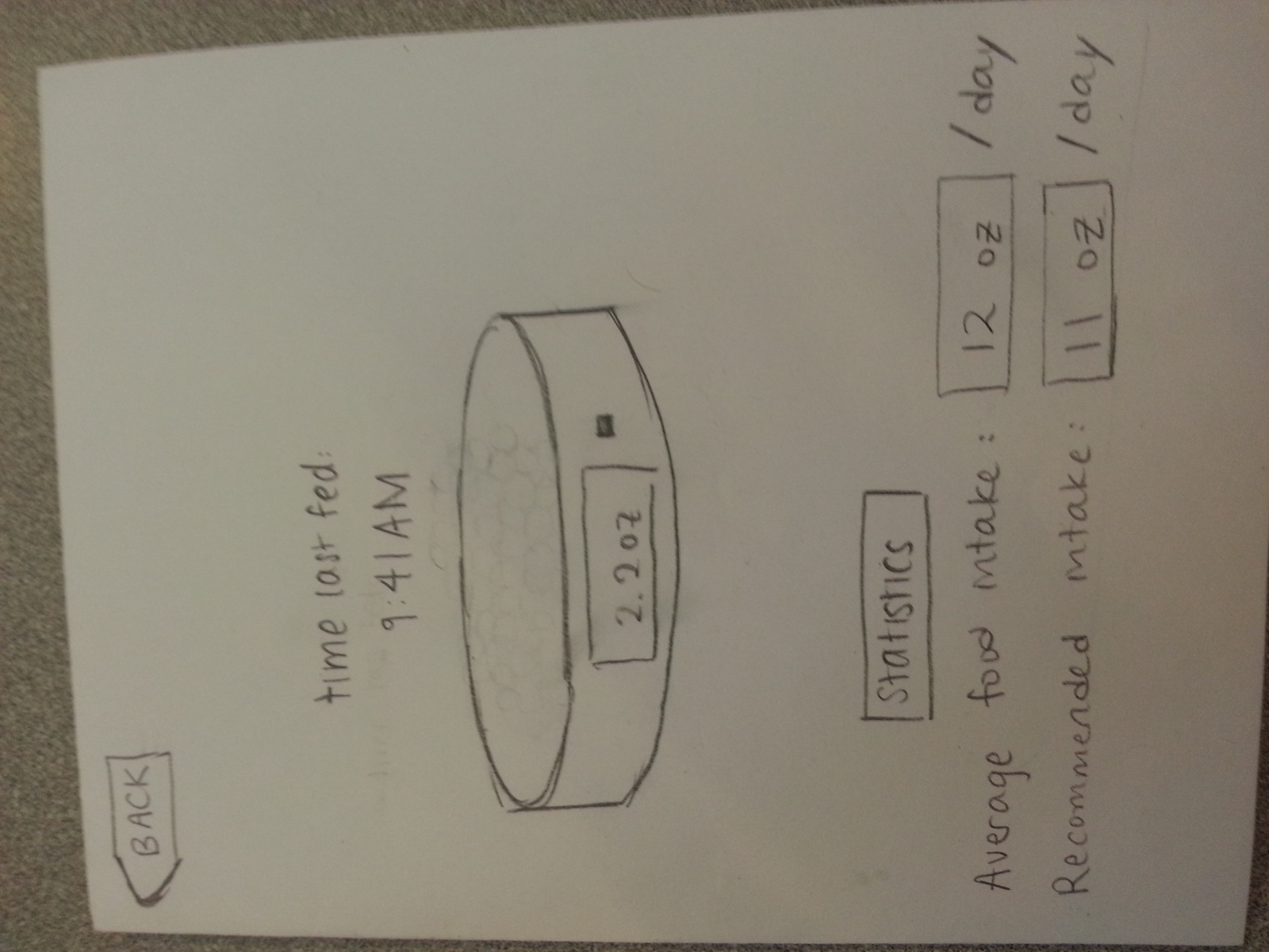
Diet information for the dog, where it shows the bowl’s current filled amount, and the average information for the dog’s intake. (Task 1)

  20130329_163011

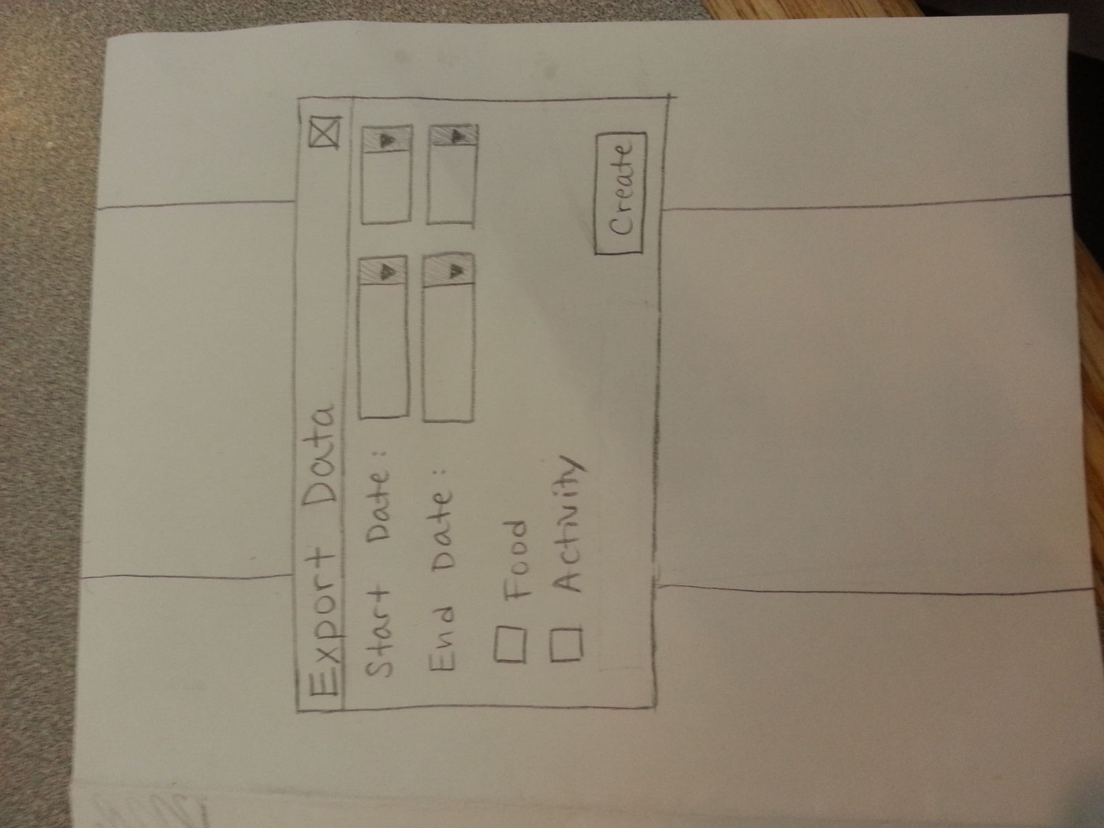
The function for exporting data to the veterinarian or other caretakers for the dog. (Task 3)

e) Task Testing Descriptions

Task 1: Checking when the dog was last fed, and deciding when/whether to feed their dog.

The user will have two ways to perform this task. One, they may look at the color of an LED on the dog bowl (which indicates how long it has been since the bowl was filled), or look at the exact time of the last feeding, which is also displayed on the bowl. Alternatively, they can look at the app, which will display the time the bowl was last filled.

If no feeding has been detected for a long time, the user will receive a direct alert warning them that they have not fed their dog. We intend for our prototype to be tested using both the bowl alone and using both the mobile application and the bowl.  The “backstory” for the bowl alone is that the owner is at home and wishes to see if they should feed their dog, and/or whether someone else in their family has already fed their dog recently. The “backstory” for the mobile application + bowl prototype test is that the owner has gotten a notification that they have forgotten to feed their dog, and they check the mobile application for more information and subsequently go to fill their dog’s bowl.

Task 2: Checking and regulating the activity/healthiness of your dog

The user can check the activity level of his or her dog by looking at its collar – a single LED will only light if the dog has lower levels of activity than usual (for the past 24 hours). The user can also find more detailed information about their dog’s activity level by looking at the app, which shows the dog’s level of activity throughout the day, week, or month, and assigns a general “wellness” level according to the dog’s activity level that is displayed on the home screen as a meter. This prototype should be tested in two ways — using the collar alone or just the mobile application.  The backstory for testing only the collar prototype is that the owner has just arrived home from work and wants to know whether the dog needs to be taken on a walk (or whether it has received enough physical activity from being outside during the day when the owner was not home) — using the LED on the collar, the owner can make a decision.  The backstory for testing only the mobile prototype is that the owner has recently changed their work schedule and wishes to see whether this has adversely affected their ability to give their dog enough physical activity — they can check this by looking at the week/month views of the mobile app.

Task 3: Generate, view, and share a summary of your dog’s health over a long period of time.

The user can generate, view, and share a summary of their dog’s health over a long period of time by using the “Export data” button on the application, which also has the option of sending the information to someone else (probably a veterinarian).  This mobile application prototype will be tested by having users interact with the relevant prototype screens.  The backstory for testing is that the user has a veterinarian appointment the next day, but does not remember exactly how much they have been feeding their dog/how much activity it has gotten, and would not be able to tell the vet much from memory.  Using the prototype, they can automatically send detailed information straight to the vet.

Video of the tasks here: https://www.youtube.com/watch?v=KIixVJ21zQ0

f) Discussion of Prototype

We started the process of making our prototype by first brainstorming the most convenient ways that a user could perform these tasks. Continuous revisions were made until we believed we had streamlined these tasks as much as possible within our technological limitations. Afterwards, we created an initial design for the application, and quickly created prototypes for the mobile application, collar, and bowl.  While not particularly revolutionary, we used a physical bowl (made out of paper) to simulate the usage of the bowl. While we were considering including some surrogate imitation of a dog, we decided against it, as all of our ideas (hand puppets, images, video, etc) were considered too distracting for the tester. Because the collar is an interface ideally out of the hands of the user, we decided to simply show them a prototype of what they would see on the collar, as well as their data updating on the application.

Perhaps the most difficult aspect of making the prototype was figuring out how we could make the user “interact” with their dog, without actually bringing in their dog.  It was also difficult to design prototypes that had minimal design (i.e. tested all of the relevant tasks, while not distracting the user with “flashy” icons or features).  We found that the paper prototypes worked well to help us envision how the app would look, and how it would be improved. The prototypes for the bowl and collar were also helpful in helping us identify exactly what information the user would need to know and what was superfluous.  Using very simple prototype materials/designs for the bowl and collar were helpful to our thinking/design process. While the paper prototypes submitted in this assignment were created through multiple revisions, the prototype will probably continue to be revised for P4.

Lab 2 – Team Chewie (Chewbacca)

Team Members
Stephen Cognetta (cognetta@)
Eugene Lee (eugenel@)
Jean Choi (jeanchoi@)
Karena Cai (kcai@)

Group Number: 14

Description
Our musical instrument was a head-banging music maker. The accelerometer, which is attached to a hat, detects when the user has done a sudden motion (like head banging). When this motion is detected, the tempo of the song that is playing will match the rate at which you are banging your head. By varying the location of touch along a linear sensor, the pitch of the song can also be changed. We thought that our project was a success because we were able to become familiar with the accelerometer while also making a cool project that created music with the motion of the user’s body. As an extension of this project, we could somehow attach the accelerometer to someone’s feet so that when they exercised, the beat of the music would match the rate at which they were running. We also thought that our design could be improved so it was less visible and less bulky.

PROTOTYPE 1 : Ambient Music Generator

This instrument by default emits an ambient noise. When a sudden jerk in the accelerometer is detected, it will emit a dolphin noise. Such a device could be attached to children’s toys that make playing with toys even more fun!
Used CHuck and Processing.
PROTOTYPE 2 : Two-Dimensional Music Player

This instrument uses a two-dimensional sensing technique to change both the pitch and the tempo of a song. If force is applied to the FSR, the tempo decreases. Meanwhile, by sliding the FSR along the soft potentiometer (linear sensor), the pitch will vary.

Head-Banging Music Maker. Final project for this lab. We created a hat that would respond to the movements of the head, if the head jerks fast, the music would play faster, and vice versa. It won’t play at all if the head isn’t moved.

List of Parts
– Arduino Uno
– jumper wires
– accelerometer
– Buzzer
– Hat

Instructions on how to recreate the Head-Banging Music Maker
We attach the buzzer and accelerometer to the device as shown in the picture below. (basically, the accelerometer is wired in as was done in Step 5 of the lab, using the AREF pin, and the buzzer is hooked up to the arduino board). Then attach to the hat as shown. Most of the work is performed in the code, which is shown below.

ttt

hat

Head Bangin’ Source Code

/*
  Graph

 A simple example of communication from the Arduino board to the computer:
 the value of analog input 0 is sent out the serial port.  We call this "serial"
 communication because the connection appears to both the Arduino and the
 computer as a serial port, even though it may actually use
 a USB cable. Bytes are sent one after another (serially) from the Arduino
 to the computer.

 You can use the Arduino serial monitor to view the sent data, or it can
 be read by Processing, PD, Max/MSP, or any other program capable of reading 
 data from a serial port.  The Processing code below graphs the data received 
 so you can see the value of the analog input changing over time.

 The circuit:
 Any analog input sensor is attached to analog in pin 0.

 created 2006
 by David A. Mellis
 modified 9 Apr 2012
 by Tom Igoe and Scott Fitzgerald

 This example code is in the public domain.

 http://www.arduino.cc/en/Tutorial/Graph
 */

// ******************************************************
// CHORD INITIALIZATION
// ******************************************************

const int C = 24,
          D = 27,
          E = 30,
          F = 32,
          G = 36,
          A = 40,
          B = 45,
          C2 = 48,
          H = 0;

int twinkleStar[] = { C, C, G, G, A, A, G, H,
                      F, F, E, E, D, D, C, H,
                      G, G, F, F, E, E, D, H,
                      G, G, F, F, E, E, D, H,
                      C, C, G, G, A, A, G, H,
                      F, F, E, E, D, D, C, H};
int songLength = 48;
int songStep = 0;

int singleNote[] = { 1, 1, 1, 1 };
int majorChord[] = { 4, 5, 6, 0 };
int minorChord[] = { 10, 12, 15, 0 };
int seventhChord[] = { 20, 25, 30, 36 };
int majorChordLength = 3;
int *chords[] = { singleNote, majorChord, minorChord, seventhChord };
const int chordsLength = 4;

int chordType = 0;                // changes between chords[]
int arpStep = 0;                  // changes between chord frequencies

// ******************************************************
// INPUT INITIALIZATION
 // ******************************************************
const int linPin = A1;
const int xPin = A5;
const int yPin = A4;
const int zPin = A3;
const int tonePin = 10;
const int groundpin = A2; // analog input pin 2
const int powerpin = A0; // analog input pin 0
const int proxPin = A6; // analog input pin 6

// ******************************************************
// MAIN LOOP
// ******************************************************

unsigned int tempo;
unsigned int frequency;
unsigned int chordFrequency;
int currentBang;
int bangInterval = 0;
int minimumBangInterval = 70;
int maximumBangInterval = 200;

void setup() {
  // initialize the serial communication:
  Serial.begin(9600);

  pinMode(groundpin, OUTPUT);
 pinMode(powerpin, OUTPUT);
 digitalWrite(groundpin, LOW); 
 digitalWrite(powerpin, HIGH);
}

int prevX = 400;
boolean rising = false;
boolean falling = false;
int mini, maxi, diff;

void loop() {
  int linReading = analogRead(linPin);
  int xReading = analogRead(xPin);
  int yReading = analogRead(yPin);
  int zReading = analogRead(zPin);

  // send the value of analog input 0:
  //int potReading = analogRead(potPin);
 // int btnReading = digitalRead(btnPin);
  // send the value of analog input 0:

  // wait a bit for the analog-to-digital converter 
  // to stabilize after the last reading:
  delay(2);

  int x, y, z;
  x = xReading;
  y = yReading;
  z = zReading;
  if (prevX < x) {
    rising = true;
    falling = false;
  } else {
    rising = false;
    falling = true;
  }
  prevX = x;
  if (falling == true)    mini = x;
  if (rising == true)     maxi = x;
  diff = maxi - mini;

  /*Serial.print(x);
  Serial.print("\t");
  Serial.print(prevX);
  Serial.print("\t");
  Serial.print(mini);
  Serial.print("\t");
  Serial.print(maxi);
  Serial.print("\t");
  Serial.println(diff);*/

  int * chord = twinkleStar;

  //measure the time
  if (bangInterval < maximumBangInterval)     bangInterval++;   //when head bang is detected      if (diff > 80 && bangInterval > minimumBangInterval) {
    currentBang = bangInterval;
    bangInterval = 0;

  //  Serial.print(tempo);
  //  Serial.print(",");
    Serial.println(chordFrequency);

    unsigned int tempo = currentBang*2;
    unsigned int duration = tempo - tempo / 20;

    float chordFactor = (float)chord[songStep] / (float)chord[0];
    if (linReading < 1020)
      frequency = 500;
    chordFrequency = frequency * chordFactor;
    tone(tonePin, chordFrequency, duration);

     Serial.print(songStep);
    Serial.print(" ");
    Serial.print(chordFrequency);
    Serial.print(" ");
    Serial.print(chordFactor);
    Serial.print(" ");
    Serial.println(currentBang);

    delay(tempo);
    songStep = songStep < songLength - 1 ? songStep + 1 : 0;

     chordFactor = (float)chord[songStep] / (float)chord[0];
    /*if (linReading < 1020)
      frequency = linReading;*/
      frequency = 500;
    chordFrequency = frequency * chordFactor;
    tone(tonePin, chordFrequency, duration);

    Serial.print(songStep);
    Serial.print(" ");
    Serial.print(chordFrequency);
    Serial.print(" ");
    Serial.print(chordFactor);
    Serial.print(" ");
    Serial.println(currentBang);

    songStep = songStep < songLength - 1 ? songStep + 1 : 0;
  }

}

A2 – eugene L

1. OBSERVATION

Person 1.
Student –  Female, outside COS 326 Lecture.
Status – Next class in the same building
Activity – Sitting. Doing work on paper, chat with friends about what they are doing.
Time taken – 14 minutes of waiting.

Person 2.
Student – Male, outside COS 326 Lecture.
Status – same as above
Activity – Sitting. Using their phone (texting), while eating lunch. Pulls out laptop for a bit to check something. Once in the lecture hall, before class starts, he checks several websites on his laptop, particularly his calendar and email.
Time taken – 10 minutes of waiting

Insights: When they are sitting, people are able to do things that involves both their hands and their full visual attention. They have to check every once in a while to see if they can enter their lecture hall. Once in the lecture hall, they are much more likely to take out their laptop.

Person 3.
Teacher – Male. Medium sized classroom.
Status – arrives 10 minutes early to class
Activity – spends about 5 minutes getting everything set up. Spends the next 5 minutes looking around.
When interviewed: said he was preparing what to say

Insights: teachers spend a substantial part of their 10 minutes physically setting their classes up.

Person 4.
Student. Male. On bicycle
Status – comes from somewhere south campus somewhat hurriedly. Arriving just on time.
Activity – just biking

Person 5
Student. Male. Walking
Status – comes from somewhere west campus. Well before class begins. Walks pretty slowly, taking their time.
Activity – using their cellphone sometimes. Otherwise just walking.

Insights. When alone, people spend a lot of time simply focused on transportation. Little usage of devices, especially on vehicles

Person 6+7. Male and Female. Walking together to a class
Status – somewhere north campus going to south campus
Activity – Talking about their project they are working on. Complaints about their workload, other typical Princeton-esque blather.

Insights. When with others, people spend the majority of their time talking. Very little usage of devices.

Overall insights: There are many kinds of usages of these 10 minutes, depending on the following factors:

  • Distance needed to travel – the longer it is, the more time is spent in transit. While in transit, people are less likely to perform useful activities (besides transportation)
  • Transportation method – vehicle users are much less likely to use their devices in transit. However, the time spent in transit is significantly less, meaning they have more time to sit and use their less mobile devices.
  • Number of people in your group – More people means less device use. Most of their attention is focused on the conversation
  • Amount of time before their event – less time means more attention spent on travel. No time for distractions

2. “FULL” LIST OF IDEAS

  1. Bicycle HUD display allows for use of devices using ‘motorcycle’ Handlebar controls
  2. See the current inventory of your bag, and be warned when you don’t have something you may need
  3. Interact with people leaving from/going to the same class through a network you automatically join once class ends, and leave once class begins
  4. Compares friends’ walking paths to see if you can meet up with them after a given class
  5. Review for class by quizzing you questions based on your notes; or through the network in 3, optional ungraded questions from the teacher that allow you to see how well you fare relative to others in the class and relative to expectations. You choose if you want to study for your previous or some future class.
  6. A device that allows you to close your eyes as you walk, guiding you with vibrations, leaving you with more energy when you arrive
  7. Quick on-the-go food carts along busy paths selling quick food/drink/supplies
  8. Public bike system
  9. Wireless energy allowing you to charge your devices as you walk
  10. Virtual classes – completely remove the 10 minutes between classes, because you don’t need to move.
  11. Better planned classes – use closer classrooms so the general populace of Princeton has less movement.
  12. A nap alarm that you don’t need to set that will wake you up in time for your next class in time, including travel time. If you’re still in bed, then including preparation time
  13. Partially access your computer as you walk by accessing the few files and websites you were most recently accessing on your computer – can read your text files to you: good for proofreading
  14. A feed of single things (emails, texts) that you handle one at a time to reduce your attentive strain
  15. Persistent UI (glasses/holographic screen) that you don’t have to hold, which switches mode contextually based on if your in a class, in transit, working, talking, etc
  16. Smart paper/files that knows which class its for and automatically uploads its contents onto your computer. (Paper = a physical data storage device that always displays its contents.) (related to 13)

3. THE TWO IDEAS CHOSEN

  1. Combination of 2.13 and 2.16: Access your most recently used files and papers related to your class as you travel.
    Rationale: Your binder and your computer are two things you cannot access at all when you travel; this opens up that capability. 
  2. 2.2: See the inventory of your bag, and be warned
    Rationale: Particularly when you are rushed, you often will forget to include certain objects in your bag that you can’t afford to go back to get, like papers you have to submit.

4.1 PROTOYPE OF 3.1

This allows you to be able to access relevant files allows you to select the files you need, without being swamped. This is also related to ubiquitous computing, as it allows you to access information you created on a non-mobile device (including paper). You don’t even need to have your actual computer or papers with you – you can just bring the device, and it’ll have the things you need.

IMG_20130301_233652

Here is the wearable device, which takes data from your computer and papers and gives them to whatever output device it is linked to – be it a HUD, a cellphone, or another computer.  In this case we chose a cellphone.

IMG_20130301_233917

On the display, we can see documents organized by source. In each sublist, the documents are ordered by time accessed (the computer sublist) or by importance (the binder sublist). Importance is based primarily on which class is coming up.

Clicking on one will open an app capable of opening this file


Another important part of the technology is being able to easily sort which files are connected to which class. Therefore, there is an app that allows you to switch modes. When you are in a particular mode, all files you access and papers you print are tagged to that mode unless specified otherwise. However, papers and files can be pre-tagged to other modes; such as pre-tagged handouts you receive, and emails sent for a particular class.

This could be on the device itself, but in this case I chose to use a cellphone (as a physical device could not be as easily prototyped). This app allows you to create and set which mode you are in.

IMG_20130301_233722

The technology to tag pieces of paper is obviously far in the future, but could involve some kind of printed tag through a printer.

4.2 PROTOTYPE OF 3.2 

Desired functionality:
Your object checking bag can tell you easy omissions like forgetting your wallet or cellphone or to bring an umbrella, but your bag would also checks your schedule. It could tell you things like – bring a lunch, because you don’t have time to eat today.

IMG_20130301_233621

This shows the device with current vs future technology. Currently, object recognition is only guaranteed with RFID chips or some other tag indicator. In the future, objects will be recognized through some 3D sensor, or perhaps all objects will come with some form of tag defining the object.

The app has two lists, an ‘in’ and an ‘out’ list that tells you if something is in or out of his list (pictures in the feedback section to avoid redundancy).

The bag will also rate things of higher or lower importance, based on the context. For example, a laptop is of critical importance immediately before a COS class (usually). An umbrella is not of importance if it is not raining. it will list things in the ‘out’ list according to its importance.

5. WHAT PEOPLE THOUGHT

The Bag

He was intrigued by the idea, noting the fact that he often forgot things as he left.
IMG_20130301_233206
As he added a mouse into the bag, the mouse appeared in his ‘in’ list
IMG_20130301_233344
(the list is long because he is ‘scrolling’ down.)
IMG_20130301_233233
The user liked how the bag would audibly alert him to missing items of high priority when he left the room, such as umbrellas if it is currently raining. He did raise the concern of the subjectivity of ‘high priority”
IMG_20130301_233506
The user adds a water bottle to his bag due to the reminder from the list. The item automatically disappeared from the ‘out’ bag and appeared in his ‘in’ bag list. (not pictured)
IMG_20130301_233155
The user did not know how to remove an item from the list if he did not want to be reminded of it’s presence/absence. I told him to long press it and delete it. He also did not know how to switch between stuff in and stuff out of his bag, and I told him to swipe the screen to switch between the two modes.
He also seemed concerned that he could feel too safe, and thus be more likely to forget things the app cannot detect, such as printing out papers.

6. INSIGHTS

From the test, I realized that there should probably be a permanent ‘X’ button if you want to see the notification of a particular item or not. I also realize

Analysis of Device 1 raised the question of which files you need now, and which ones you don’t. Even if a computer asked you directly, you wouldn’t be able to answer that immediately. If a user uses the device and isn’t able to find the file they need, they will get frustrated and be discouraged to use the device.

In addition, people don’t always need things for ‘now’, but also can check things that are most urgent. This is partially covered by giving you access to files you most recently accessed on your other devices, but does not include everything

There is also the increased hassle of having to tag each file with a particular class name. This was partially addressed with the different ‘modes’ you are in, but even this is somewhat annoying.

In order for Device 2 to work fully as intended, would constantly pester you with irrelevant questions, like “did you forget your charger?” It could also make people put less useful items into their bag when they don’t really need to, thus weighing them down. On a more specific note, it could also prove counteractive to dieting if it reminds you to bring food, assuming you will skip a meal.

More importantly, this is not feasible in current day. Manually applying an RFID tag onto every object is counter to the device’s goal of ease of use.

The combination of these two technologies could prove useful, as ‘smart paper’ would allow your bag to determine if you put in necessary files into your bag. In conjunction with knowing which documents you were most recently working on would tell your bag if you printed something out or not.

Lab 1 – MusicVisualizer

Team Chewbacca: (Group 14)
Karena Cai
Stephen Cognetta
Jean Choi
Eugene Lee

We built a music-visualizer device, where you can play music and visualize the music being played. Using the soft pot sensor to determine pitch, the button to change arpeggio modes, and the potentiometer changes tempo. We used the buzzer to output the sound and Processing to visualize the outputs. We built it because it’s cool, we wanted to integrate Processing with our device, we wanted to do a music project, and we thought it might be useful for helping people who can’t read music to visualize basic music notes and chords in an intuitive way. Overall, this was a successful project in that we were able to visualize the music we played accurately. We didn’t quite get perfect measurements, the soft pot sensor did not seem to exhibit linear behavior. Another issue we had was that we originally attempted to make a different idea, which just played music and changed between tracks: after completing this we ultimately decided to switch to our current idea.

Three Sketches:

20130301_18285320130301_184427


20130301_185602

Storyboard:

photo

Video

Materials:
Potentiometer
Buzzer
Soft Pot Sensor
Button

Instructions:
Hook up the inputs: potentiometer, the soft pot, button
– Hook up the outputs: buzzer
– After hooking up those inputs/outputs through the appropriate means, develop the Arduino and Processing code to take the three inputs and output them to the buzzer and to Processing. The detailed circuit diagram is shown above, following that diagram should be sufficient to recreate our design.


Borrowed code/instructions from:
http://www.arduino.cc/en/Tutorial/Graph (Arduino -> Processing code)
by David A. Mellis modified by Tom Igoe and Scott Fitzgerald

Source code

  • Processing Visualizer:
    // Graphing sketch

   // This program takes ASCII-encoded strings
   // from the serial port at 9600 baud and graphs them. It expects values in the
   // range 0 to 1023, followed by a newline, or newline and carriage return

   // Created 20 Apr 2005
   // Updated 18 Jan 2008
   // by Tom Igoe
   // This example code is in the public domain.

   import processing.serial.*;

   Serial myPort;        // The serial port
   int xPos = 1;         // horizontal position of the graph

   void setup () {
     // set the window size:
     size(1000, 300);        

     // List all the available serial ports
     println(Serial.list());
     // I know that the first port in the serial list on my mac
     // is always my  Arduino, so I open Serial.list()[0].
     // Open whatever port is the one you're using.
     myPort = new Serial(this, Serial.list()[0], 9600);
     // don't generate a serialEvent() unless you get a newline character:
     myPort.bufferUntil('\n');
     // set inital background:
     background(0);
   }
   void draw () {
   // everything happens in the serialEvent()
   }

   void serialEvent (Serial myPort) {
     // get the ASCII string:
     String inString = myPort.readStringUntil('\n');
     // 0 = lin/frequency, 1 = pot/tempo   

     String[] inStrings = split(inString, ',');
     float[] inBytes = new float[inStrings.length];
     println(inString);
     for (int i = 0 ; i < inStrings.length; i++) {          inStrings[i] = trim(inStrings[i]);          inBytes[i] = float(inStrings[i]);      }      //println(inBytes);            inBytes[0] = map(inBytes[0], 0, 1023, 0, width/3);      float tempo = inBytes[0];      inBytes[1] = map(inBytes[1], 0, 1023, 0, height/2);      float frequency = inBytes[1];            float rectWidth = tempo;            // at the edge of the screen, go back to the beginning:      if (xPos + rectWidth >= width) {
       xPos = 0;
       background(0); 
     } 

     //println(rectangleWidth);
     // draw the line:
     int color1 = color(127, 34, 255 - frequency);
     fill(color1);
     rect(xPos, 0, rectWidth, (int)frequency);

     // increment the horizontal position:
     xPos += rectWidth;
   } // END serialEvent
  •  Arduino
/*
  Graph

 A simple example of communication from the Arduino board to the computer:
 the value of analog input 0 is sent out the serial port.  We call this "serial"
 communication because the connection appears to both the Arduino and the
 computer as a serial port, even though it may actually use
 a USB cable. Bytes are sent one after another (serially) from the Arduino
 to the computer.

 You can use the Arduino serial monitor to view the sent data, or it can
 be read by Processing, PD, Max/MSP, or any other program capable of reading 
 data from a serial port.  The Processing code below graphs the data received 
 so you can see the value of the analog input changing over time.

 The circuit:
 Any analog input sensor is attached to analog in pin 0.

 created 2006
 by David A. Mellis
 modified 9 Apr 2012
 by Tom Igoe and Scott Fitzgerald

 This example code is in the public domain.

 http://www.arduino.cc/en/Tutorial/Graph
 */

// ******************************************************
// CHORD INITIALIZATION
// ******************************************************
int singleNote[] = { 1, 1, 1, 1 };
int majorChord[] = { 4, 5, 6, 0 };
int minorChord[] = { 10, 12, 15, 0 };
int seventhChord[] = { 20, 25, 30, 36 };
int majorChordLength = 3;
int *chords[] = { singleNote, majorChord, minorChord, seventhChord };
const int chordsLength = 4;

int chordType = 0;                // changes between chords[]
int arpStep = 0;                  // changes between chord frequencies

// ******************************************************
// INPUT INITIALIZATION
// ******************************************************
const int linPin = A0; 
const int potPin = A2;
const int btnPin = 12;
const int tonePin = 10;
boolean firstButtonCycle = false; // button 'debouncer'

// pressing the button changes the chord number
void buttonControl(int btnReading) {
  if(btnReading == HIGH){
    // firstButtonCycle prevents the device from changing songs rapidly when 
    // the button is held down
    if (firstButtonCycle == false) {
      firstButtonCycle = true;
        // change the chord type
        chordType = chordType < chordsLength - 1 ? chordType + 1 : 0;
      }
  }
  if(btnReading == LOW){
     firstButtonCycle = false;
  }
}

// ******************************************************
// MAIN LOOP
// ******************************************************

unsigned int tempo;
unsigned int frequency;
unsigned int chordFrequency;

void setup() {
  // initialize the serial communication:
  Serial.begin(9600);
}

void loop() {
  int linReading = analogRead(linPin);
  // send the value of analog input 0:
  int potReading = analogRead(potPin);
  int btnReading = digitalRead(btnPin);
  // send the value of analog input 0:

  // wait a bit for the analog-to-digital converter 
  // to stabilize after the last reading:
  delay(2);

  tempo = potReading/3 + 10;

  buttonControl(btnReading);
  int* chord = chords[chordType];
  float chordFactor = (float)chord[arpStep] / (float)chord[0];

  if (linReading < 1020) {
    frequency = linReading;
  }
  chordFrequency = frequency * chordFactor;

  Serial.print(tempo);
  Serial.print(",");
  Serial.println(chordFrequency);
//Serial.print(",");
//  Serial.println(chordType);

  unsigned int duration = tempo - tempo / 20;
  delay(tempo);
  tone(tonePin, chordFrequency, duration);
  arpStep = arpStep < majorChordLength ? arpStep + 1 : 0;
}


Mini Lightsaber

PART I Names

Karena Cai (kcai@)
Jean Choi (jeanchoi@)
Stephen Cognetta (cognetta@)
Eugene Lee (eugenel@)

PART II

We built a mini Lightsaber, which makes ‘authentic’ lightsaber noises when held , turns on and off with a button, changes brightness based on a knob, and also changes brightness and noise frequency when you flex your wrist. We built it because it is awesome. More seriously, we built this because the focus is on the light diffuser, as per the project description, but because it also allowed us to make a lot of interesting modifications to it. The project was an immense success. Although the lightsaber wasn’t as long or bright as we would have liked, that was a limitation of resources, not of effort. We liked that it changes brightness with both the potentiometer and flex sensor, and incorporated many types of sensors. It also interfaces with the body in an interesting way, as wrist motion affects the brightness of the LEDs. We found that the LEDs on pins 3 and 11 turn off when the buzzer (on pin 8) sounded. We were not entirely sure why. We also decided not to change the color of  the tri-color LED because it would take up 3 of the 6 analog output pins. For simplicity, we decided to connect LEDs in series, so we didn’t need to use these two analog output pins. If we were to do this again, we would begin by planning our circuit design better – we had to split components between two breadboards for greater ergo-dynamics  If we were to do this again, we would try to use more powerful LEDs of the same color to closer resemble a lightsaber. Most importantly, we would like to have some kind of impact sensor so the lightsaber can react when it is used to hit things.

PART III Sketches

20130208_152222

Light Glove

Glove turns on by clicking the switch, by using the flex sensor, one can bend ones hand to alter the light in a pattern determined by their hand motions. The flex sensor would change brightness of the LEDs.

20130208_151839

Hit the right light

Replica of an arcade game, where you must hit the proper LED when its on. The six LEDs are arranged in a circle and turn on in succession. When you hit the button when the LED is on, the digital display is incremented by one. If you miss, the buzzer will go off, but the game will continue. After 10 misses, the lights will dim and the game will end.

20130208_155053

Lightsaber

The arduino will be mounted on a handle (not included) with a protruding rod, along which the LEDS will be mounted. Button will turn the LEDs on/off, the potentiometer will change the brightness of the lights, the linear sensor (not included) will change the color of the top tri-color LED. The flex sensor will detect impacts which change the brightness of the lights and emit a sound from the buzzer.

Note: we did not include the linear sensor into our final product.

PART IV : Photo and video showing final system in action

photo

The circuit

photo (3)

In action

photo (2)

Palm of glove

photo (1)

Back of glove

PART V : List of parts used in final system: 

  • 4 LEDs
  • 1 multi-colored LED
  • 2 breadboards
  • 1 push button
  • 1potentiometer
  • 1 flex sensor
  • Arduino Uno
  • plastic straw
  • buzzer
  • 5 330 Ohm resistors
  • 1 10kOhm resistor
  • wires

PART VI :  INSTRUCTIONS

  1. Set up the potentiometer so its analog output goes to pin A0, it is powered by 5V, and connected to ground.
  2. Set up the flex sensor so that it is pulled up by a 10 kOhm resistor, and its analog output goes to pin A1. Place the flex sensor on the edge of the board with the stripes facing in the direction off of the breadboard.
  3. Set up the push button so that the digital output goes to digital pin 2 of the Arduino and it is pulled down by a 330 ohm resistor.
  4. On a separate breadboard, set up the buzzer so that it is pulled up by a 330 ohm resistor and is connected to pin 8.
  5. Connect the multi-colored LED to a 330 ohm resistor connected to digital pin 9 of the Arduino. Use long electrical wires to place the LED at the top of the straw.
  6. Place two LEDs in series, pulled up by a 330 ohm resistor and digital pin 10, and thread the LEDs into the straw using electrical wire.
  7. Use electrical tape along the electrical connections to prevent short-circuiting along the straw.
  8. Attach the flex sensor onto a glove and the lightsaber should be ready to use!

PART VII :

/*
  Karena Cai
  Stephen Cognetta
  Jean Choi
  Eugene Lee
  Sets up commands for a lightsaber/wand. Buzzes
  when flex sensor detects wrist movement, and changes brightness
  from both the potentiometer and the flex sensor. The pushbutton
  turns on and off the entire laser. 
 */
// ******************************************************
// PINS
// ******************************************************

int led1 = 6;
int led2 = 9;
int led3 = 10;

int button = 2;
int buzzer = 8;

// ******************************************************
// INPUT VARIABLES
// ******************************************************
int buttonState = 0;         // variable for reading pushbutton state
boolean lightIsOn = false;   //variable for whether saber is on
boolean firstButtonCycle = false;
int ledBrightness;

// ******************************************************
// INITIALIZE
// ******************************************************
// the setup routine runs once when you press reset:
void setup() {
  // initialize serial communication at 9600 bits per second:
  Serial.begin(9600);
  pinMode(led1, OUTPUT);
  pinMode(led2, OUTPUT);
  pinMode(led3, OUTPUT);
  pinMode(button, INPUT);
}

// ******************************************************
// INPUT CONTROLS
// ******************************************************
// On button down, turn the system off and on
void togglePowerState() {
  lightIsOn = lightIsOn ? false : true;
}

// pressing the button toggles the device on/off
void buttonControl(int buttonState) {
  if(buttonState == HIGH){
    // if statment prevents the device from turning on/off rapidly when 
    // the button is held down
    if (firstButtonCycle == false) {
      firstButtonCycle = true;
      togglePowerState();
    }
  }
  if(buttonState == LOW){
     firstButtonCycle = false;
  }
}

// ******************************************************
// POWER CONTROLLER
// ******************************************************
  // controls what to do when device is on and off
  // allows device to play sounds and show appropriate brightness when on
  // if off, turn off lights and sounds.
void powerControl(int ledBrightness, int flexSensorValue) {
  if(lightIsOn)
  {
    showLight(ledBrightness);
    playTone(flexSensorValue);
  }
  else 
  {
    showLight(0);
    turnOffTone();   
  }
}

// ******************************************************
// OUTPUT CONTROLS
// ******************************************************
//displays light on LEDs with brightness int bright
void showLight(int bright) {
    analogWrite(led1, bright);
    analogWrite(led2, bright);
    analogWrite(led3, bright);
}

//plays tone if flex sensor is bent beyond some fixed amount
void playTone(int flexVal) {
    if (flexVal < 300) {
      // a higher pitched noise when the flex sensor is flexed
      tone (buzzer, (800-flexVal));
    }
    else {
      // an ambient lightsaber "hum" when the flex sensor is not flexed
      tone (buzzer, 20);
    }
}

void turnOffTone () {
   noTone (buzzer); 
}

// ******************************************************
// MAIN LOOP
// ******************************************************
// the loop routine runs over and over again forever:
void loop() {
  // read the potentiometer input on analog pin 0: (0-1023)
  int potSensorValue = analogRead(A0);
  // read the flex sensor input on analog pin 1: (~314-210)
  int flexSensorValue = analogRead(A1);
  // kind of a hack, but bendValue starts at approximately 0 
  // and increases in value with larger bends
  int bendValue = (320 - flexSensorValue);

  // tells you if the button is up or down
  buttonState = digitalRead(button);
  // led brightness is a function of the potentiometer and the degree
  // to which the flex sensor is bent
  ledBrightness = constrain(potSensorValue / 10 + bendValue, 0, 255);

  // controls what happens when the button is pushed
  buttonControl(buttonState);

  // controls what to do when the device is on or off
  powerControl(ledBrightness, flexSensorValue);

  delay(10);        // delay in between reads for stability
}