Group Members
Andrew Boik (aboik@)
Brian Huang (bwhuang@)
Kevin Lee (kevinlee@)
Saswathi Natta (snatta@)
Group 16
Description
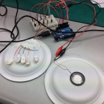
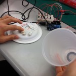
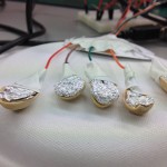
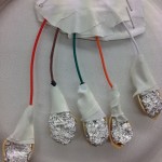
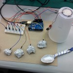
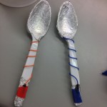
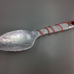
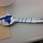
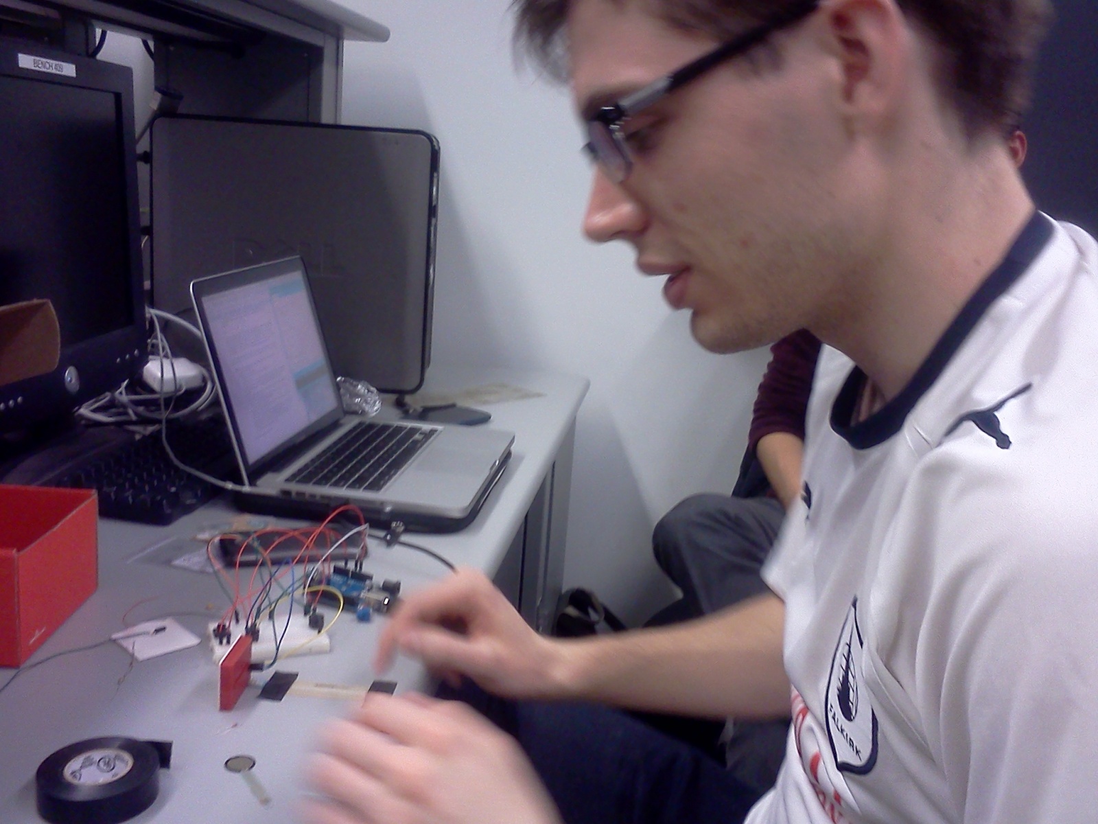
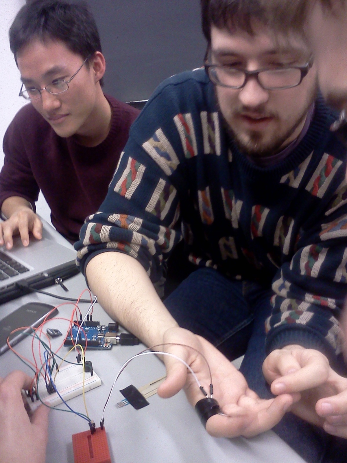
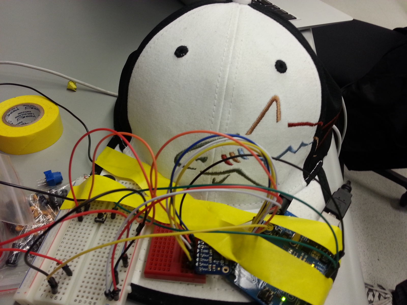
We built three instruments: Instrument of Light, a light detecting theremin from a photo resistor); Lollipop (it kind of looks like one), a proximity theremin using a capacitive proximity sensor; and La Tromba, a trumpet from three FSRs (for valves) and a flex sensor with wind sail attachment (for simulating airflow). All three worked fairly well, except the trumpet was a little difficult to control and the proximity sensor didn’t have a very wide range. In all three, we used a buzzer for sound, except for the trumpet which used a piezo element initially and then a buzzer in the final version. We ultimately decided to develop the trumpet into our final instrument. We were motivated to build this instrument because one of our group members plays trumpet, and we thought it would be interesting to create an electronic version of the instrument. Our final version featured a buzzer instead of piezo element, and we tuned our flex sensor thresholds so less blowing/bending would be required. The combination of FSRs held down is mapped to actual trumpet notes, and the signal from the flex sensor simulates the partial, so bending it further will result in a higher pitch. Overall we think the final result was a success. We liked that we could actually kind of play a scale and go through the trumpet’s full range with it. Our attachment to the FSR was a little bit of a disappointment because it was nearly impossible to control the sound by blowing on it like you would on a real trumpet, so we ended up manually bending the flex sensor instead.
Video
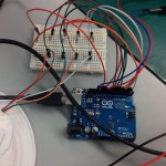
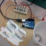
La Tromba (initial)
Use FSR sensors as 3 buttons for the trumpet and the flex sensors to sense when user blows into the trumpet. Sound is only generated when the flex sensor is bent and certain FSR sensors are pressed
Instrument of Light
Depending on the value that the photo resistor outputs, the tone that the buzzer plays will change.
Lollipop
Music by proximity: Using a capacitive proximity sensor to moderate which pitch that the buzzer plays. The pitch is higher if a person is closer to the sensor.
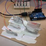
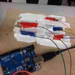
La Tromba (final)
Instructions
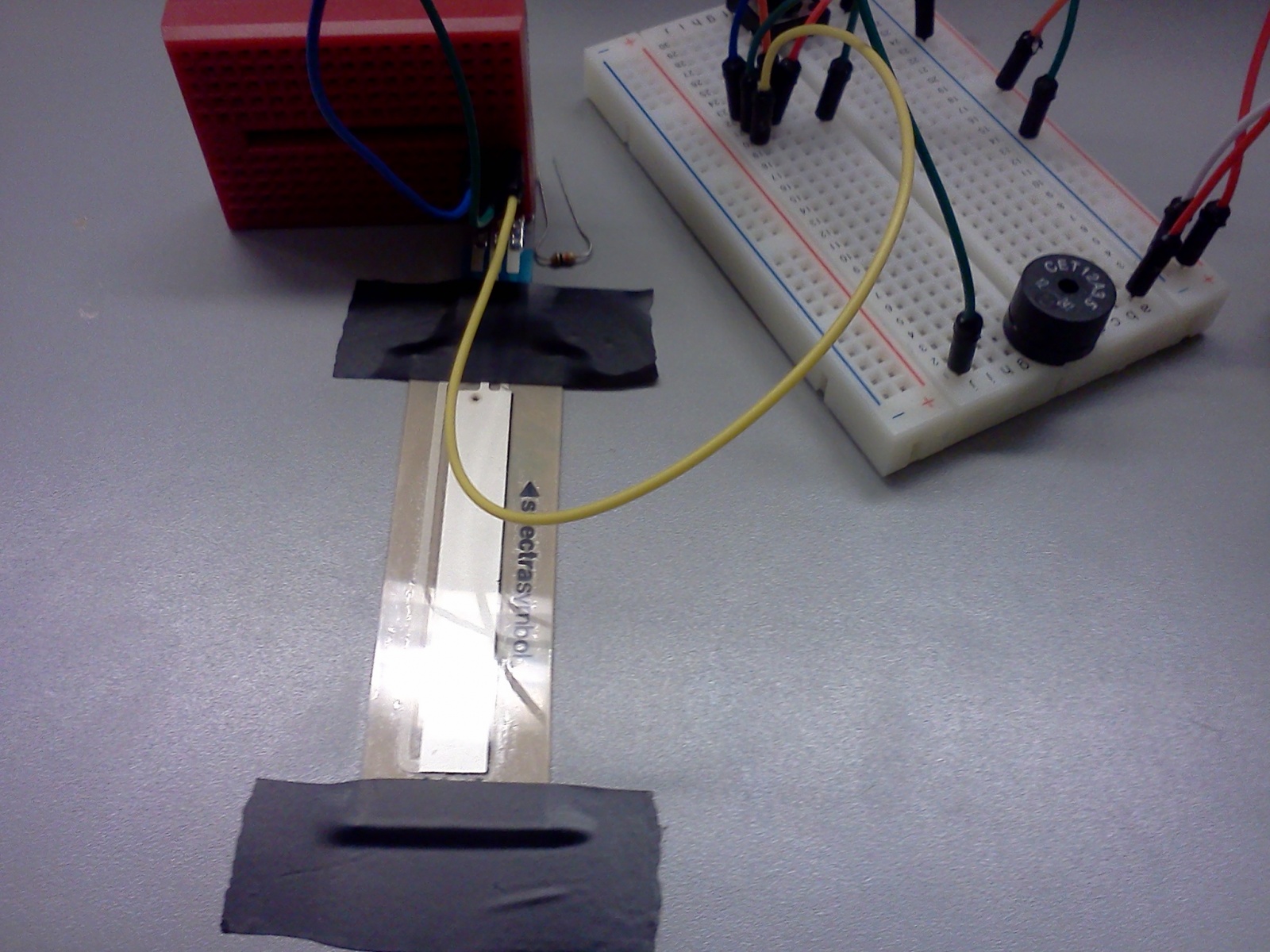
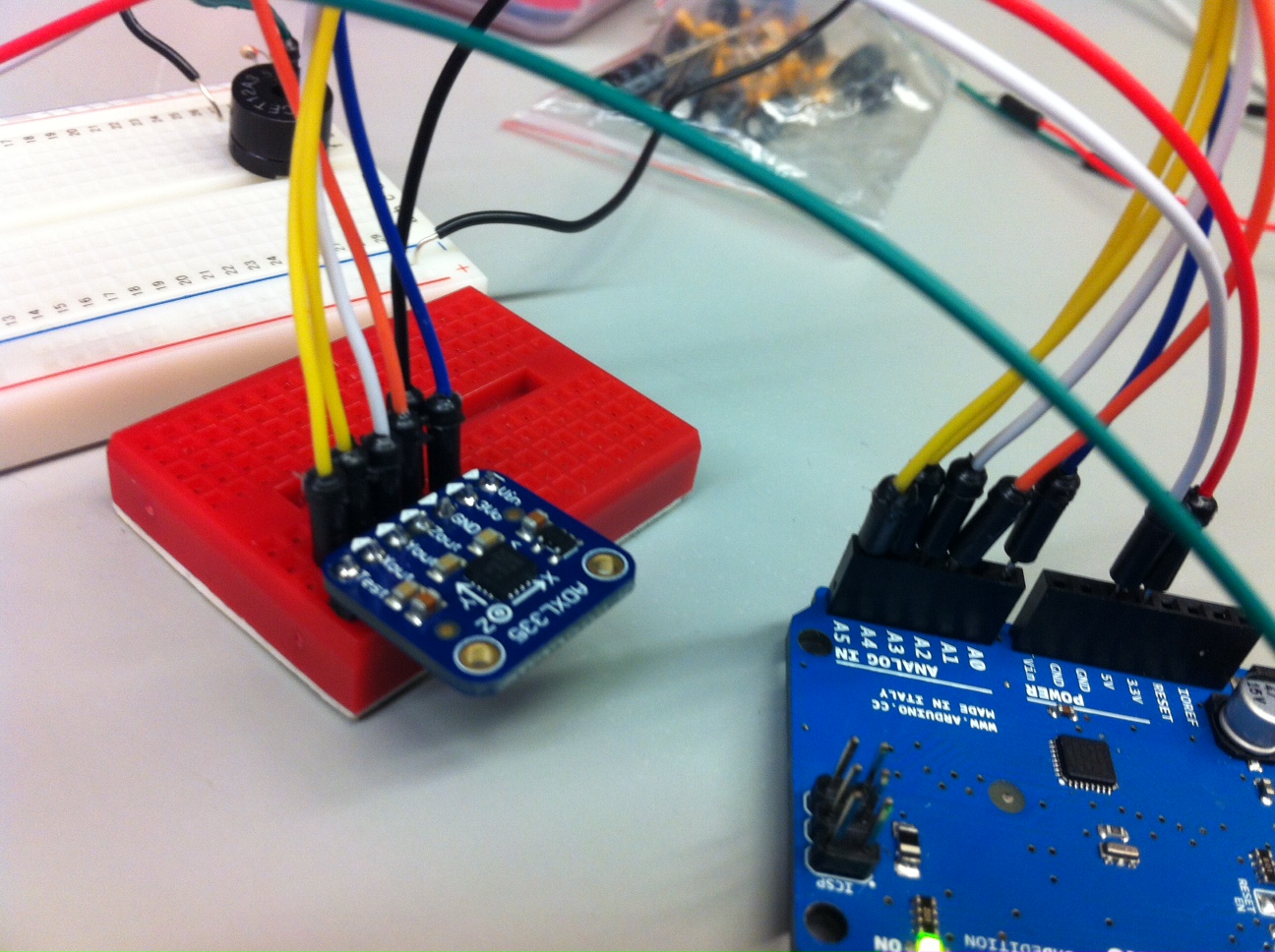
Instrument of Light (Photo resistor theremin) – Wire a photocell with a voltage divider, using a 10k resistor to ground, between one pin connected to 5V power and the other pin connected to a Arduino analog input pin to detect the resistance. Wire a buzzer to a chosen Arduino digital output pin and the shorter end to ground.
La Tromba (FSR and flex sensor trumpet) – Wire 3 FSR sensors using 10k pull down resistors for each. Each combination of buttons will produce a different tone. Wire a flex sensor with a 10K pull down resistor inside a hollow tube and when it is bent by wind being blown, it will allow the buzzer to sound a tone.Lollipop (Capacitive proximity sensor theremin) – Wire a capacitive proximity sensor, which is essentially a bit of aluminum just as in http://playground.arduino.cc//Main/CapacitiveSensor?from=Main.CapSense and connect a buzzer to the arduino to output sound depending on the proximity of the person
Materials Used in Final Instrument
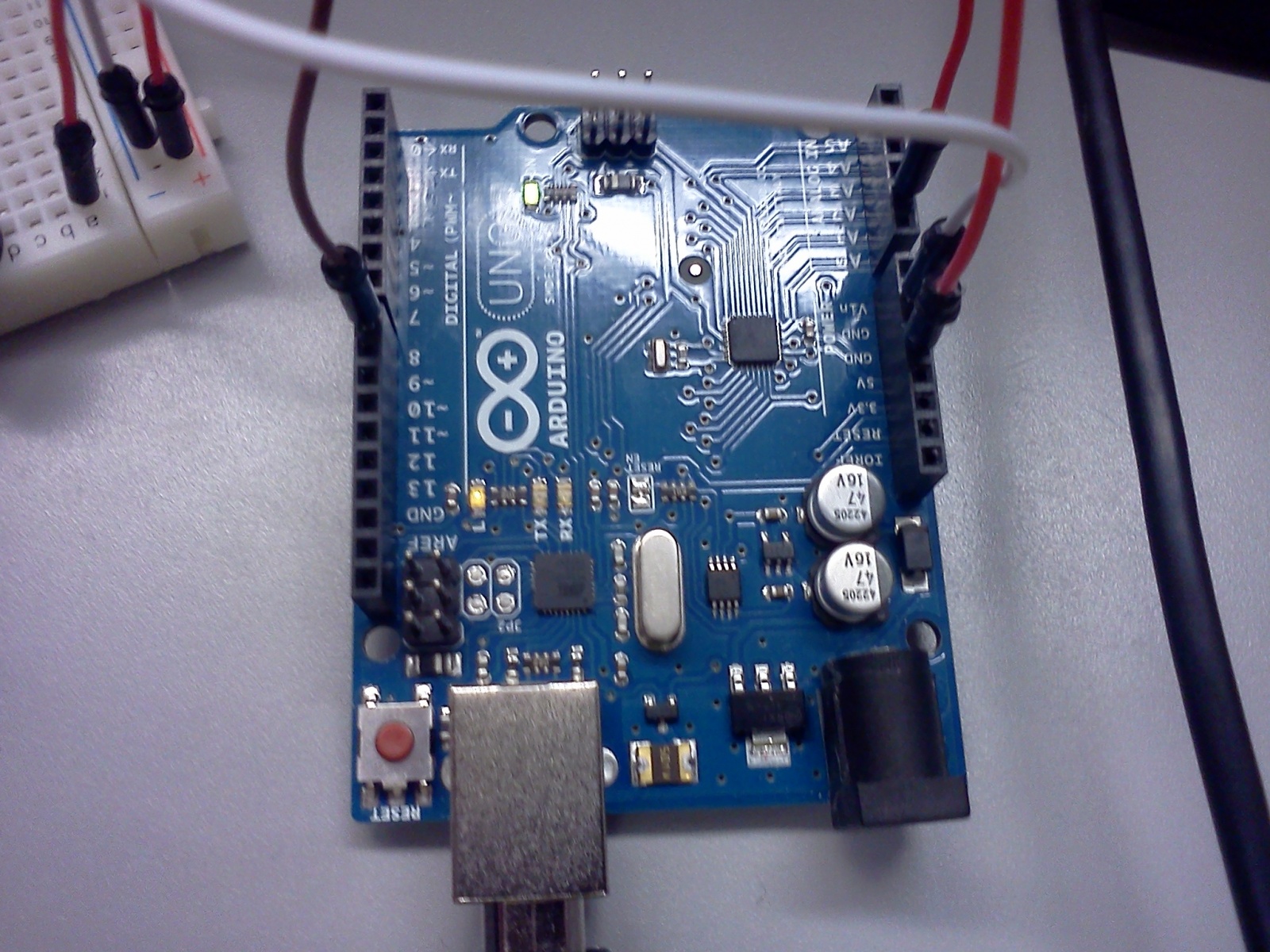
1 Arduino
1 Small breadboard
3 FSRs
1 Buzzer
1 Flex sensor
1 Paper wind sensor attachment to flex sensor
4 10K resistors
Code
La Tromba
Instrument of Light
int light_pin = A0;

int speaker_pin = 8;
void setup() {
 Serial.begin(9600);
 pinMode(8, OUTPUT);
}
void loop() {
 while(1) {
 int reading = analogRead(light_pin);
 Serial.println(reading);
 tone(speaker_pin, reading);
 }
}
Lollipop
#include <CapacitiveSensor.h>
/*
 * CapacitiveSense Library Demo Sketch
 * Paul Badger 2008 edited 2013 by Princeton HCI lab group 16
 * Uses a high value resistor e.g. 10 megohm between send pin and receive pin
 * Resistor effects sensitivity, experiment with values, 50 kilohm - 50 megohm. Larger resistor values yield larger sensor values.
 * Receive pin is the sensor pin - try different amounts of foil/metal on this pin
 * Best results are obtained if sensor foil and wire is covered with an insulator such as paper or plastic sheet
 */
/* Modified by Lab Group 16 COS 436 HCI Spring 2013 */
CapacitiveSensor cs_4_2 = CapacitiveSensor(4,2); // 1 megohm resistor between pins 4 & 2, pin 2 is sensor pin, add wire, foil
long sensorValue;
long sensorHigh = 0;
long sensorLow = 2000;
void setup()
{
 cs_4_2.set_CS_AutocaL_Millis(0xFFFFFFFF); // turn off autocalibra- //te on channel 1 - just as an example
 Serial.begin(9600);

 // upon starting, we have five seconds to give the proximity
 // detector an upper and lower bound
 while (millis() < 5000) {
 sensorValue = cs_4_2.capacitiveSensor(30);
 if (sensorValue > sensorHigh) {
 sensorHigh = sensorValue;
 }
 if (sensorValue < sensorLow) {
 sensorLow = sensorValue;
 }
 }
 Serial.print("sensorHigh = ");
 Serial.println(sensorHigh);
 Serial.print("sensorLow = ");
 Serial.println(sensorLow);
}
void loop()
{
 sensorValue = cs_4_2.capacitiveSensor(30);

 // map the sensor values to a wide range of pitches
 int pitch = map(sensorValue, sensorLow, sensorHigh, 1047, 131);

 // play the tone for [duration] ms on pin 8
 tone(8, pitch);
}