Final Submission – Team TFCS

Group Num­ber: 4
Group Name: Team TFCS
Group Mem­bers: Collin, Dale, Farhan, Ray­mond

Sum­mary: We are mak­ing a hard­ware plat­form which receives and tracks data from sen­sors that users attach to objects around them, and sends them noti­fi­ca­tions e.g. to build and rein­force habits and track activity.

Previous Posts:

P6: https://blogs.princeton.edu/humancomputerinterface/2013/05/06/p6-team-tfcs/
P5: https://blogs.princeton.edu/humancomputerinterface/2013/04/22/5642/
P4: https://blogs.princeton.edu/humancomputerinterface/2013/04/08/p4-team-tfcs/
P3: https://blogs.princeton.edu/humancomputerinterface/2013/03/29/p3-2/
P2: https://blogs.princeton.edu/humancomputerinterface/2013/03/11/p2-tfcs/
P1: http://blogs.princeton.edu/humancomputerinterface/2013/02/22/964/

Final Video

Changes from P6

Added a “delete” function and prompt to remove tracked tasks
This was a usability issue that we discovered while testing the app.

Improved the algorithm that decided when a user performed a task
The previous version had a very sensitive threshold for detecting tasks. We improved the threshold and also used a vector of multiple sensor values to decide what to use asa cutoff instead of only one sensor.

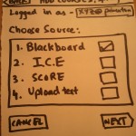
– Simplified choice of sensors to include only accelerometer and magnetometer
This was a result of the user testing which indicated that the multiple sensor choices vastly confused people. We simplified it to two straightforward choices.

– Updated text, descriptions and tutorial within the app to be more clear, based on user input from P6
– Updated each individual sensortag page to display an icon representative of the senor type, simplified the information received from the sensortag in realtime, and added a view of user’s progress in completing tasks

Goal/Design Evolution

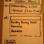
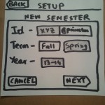
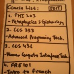
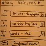
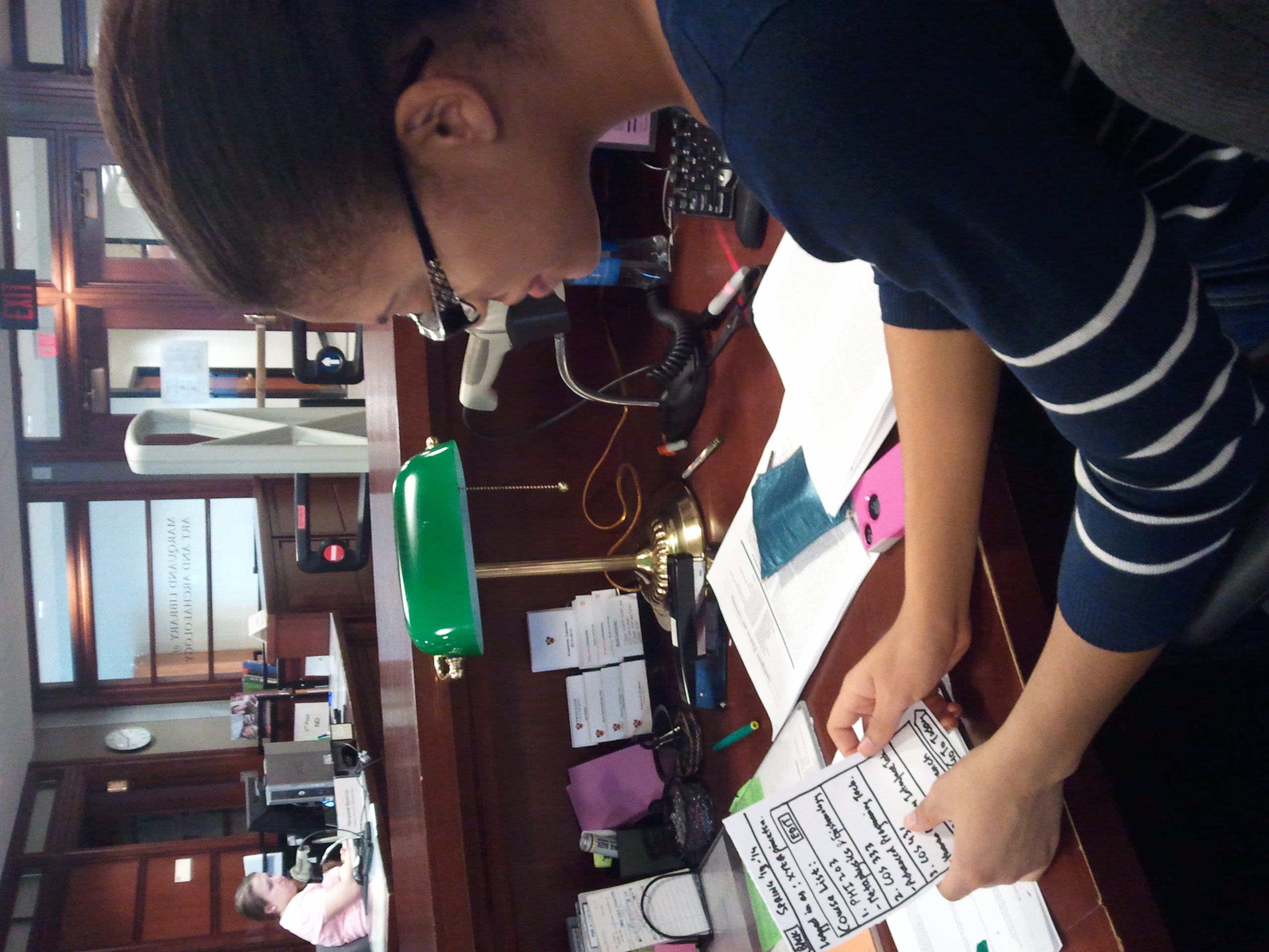
At the beginning of the semester, our goal was to make an iPhone application that allowed users to track tasks with TI sensortags, but in a much more general way than we actually implemented. For example, we wanted users to decide which sensors on our sensortag–gyroscope, magnetometer, barometer, thermometer, etc–they would use and how, and we would simply assume that users would be able to figure out how best to use these readings to fit their needs.  This proved to be a poor assumption, because it was not obvious to nontechnical users how these sensors would be used to track tasks they cared about.

We quickly reoriented ourselves to provide not a sensortag tracking app but a *task* tracking app, where the focus of the app was in registering when users took certain actions–opening a book, taking a pill from a pillbox, going to the gym with a gym bag–rather than activated the sensors on certain sensortags. Within this framework, however, we made the model for our application more general, exposing more of how the system functions by allowing them to set up sensors for each task, rather than choose from a menu of tasks within each application. This made our system’s function easier to understand for the end user, which was reflected in our second set of interviews.

Critical Evaluation
Our work over the semester provided strong evidence that this type of HCI device is quite feasible and useful. Most of our tested users expressed an interest in an automated task-tracking application and said that they would use Taskly personally. Still, one of the biggest problems of our implementation of a sensor-based habit tracking system was the size and shape of the sensors themselves. We used a sensortag designed by TI which was large and clunky, and although we built custom enclosures to make the devices less intrusive and easier to use, they were still not “ready for production.” However, as mentioned above, this is something that could easily be fixed in more mature iterations of Taskly. One reason to believe that our system might function well in the real world is that the biggest problems we encountered–the sensortag enclosures and the lack of a fully-featured iPhone app–are things we would naturally fix if we were to continue to develop Taskly. We learned a significant amount about the Bluetooth APIs through implementing this project, as well as about the specific microcontroller we used; we expect BLE devices, now supported only by the iPhone 4S and later phones, will gain significant adoption.

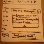
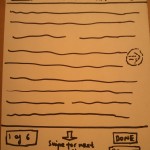
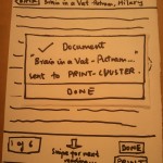
The project ended up being short on time; our lack of iOS experience (initially) made it difficult to build a substantively complex system. The iPhone application, for example, does not have all of the features we showed in our early paper-prototypes. This was partly because those interfaces revealed themselves to be excessively complicated for a system that was simple on the hardware side; however, we lost configurability and certain features in the process. On the other hand, we found learning new hardware platforms (for both iOS and the SensorTag) to be something that could definitely be accomplished over the course of weeks, especially making use of previous computer science knowledge.

One final observation that was reinforced as a result of our user testing was that the market for habit-forming apps is very narrow. People were very satified with the use cases that we presented to them and their recommendations for future applications for the system very closely aligned to the tasks we believed to be applicable for Taskly. Working on this project helped us recognize the diversity of people and needs that exist for assistive HCI-type technologies like this one, and helped us gain a better idea of what kind of people would be most receptive towards systems where they interact with embedded computers.

Moving Forward

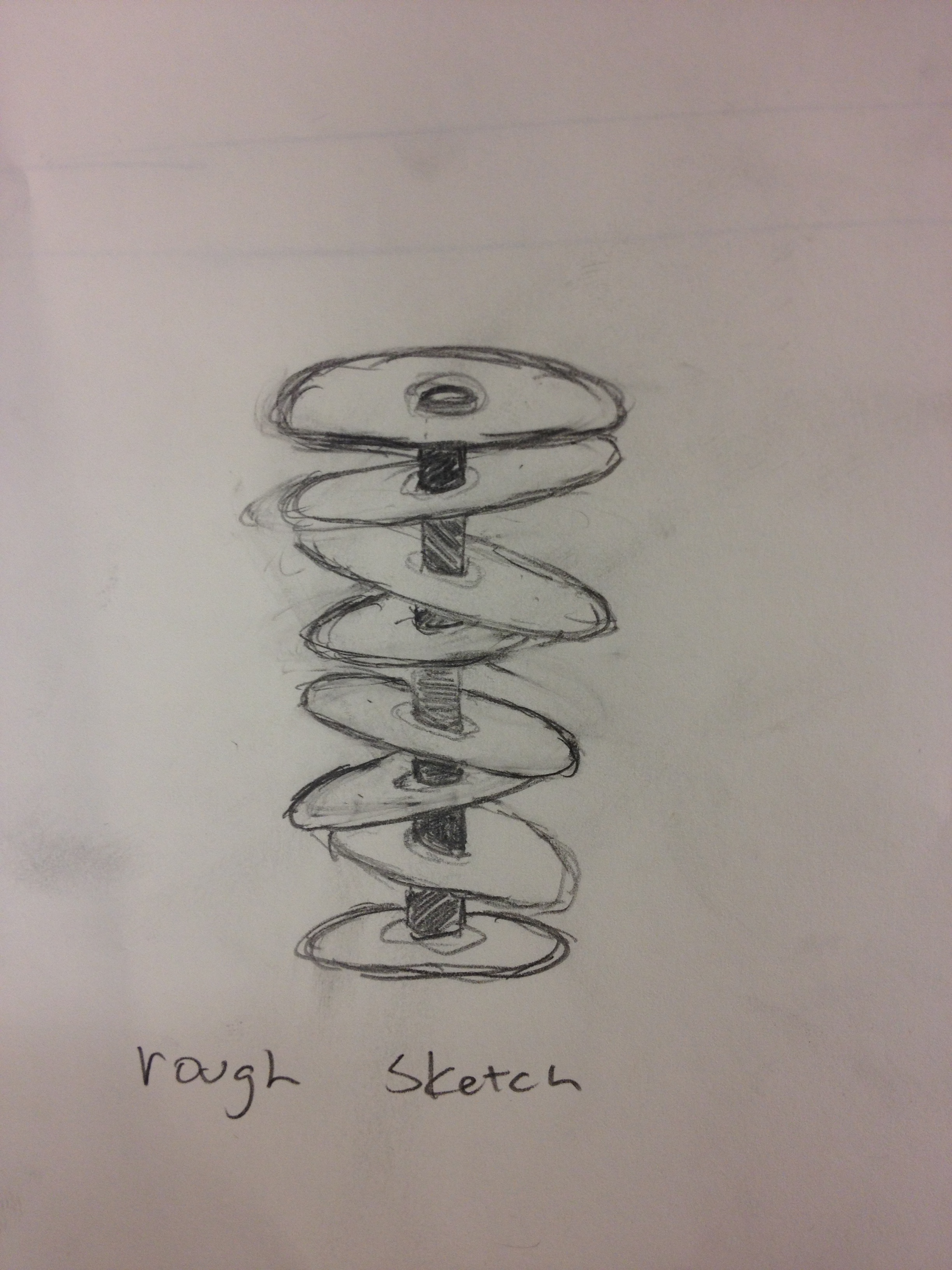
One of the things we’d most like to improve upon in later iterations of Taskly are custom sensortags. The current sensortags we use are made by Texas Instruments as a prototyping platform, but they’re rather clunky. Even though we’ve made custom enclosures for attaching these sensors to textbooks, bags, and pillboxes, they are likely still too intrusive to be useful. In a late iteration, we could create a custom sensor that uses just the bluetooth microcontroller core of the current sensortag we’re using (called the CC2541) and the relevant onboard sensors like the gyroscope, accelerometer, and magnetometer. We could fabricate our own PCB and make the entire tag slightly larger than the coin-cell battery that powers the tag. We could then 3D print a custom case that’s tiny and streamlined, so that it would be truly nonintrusive.

Beyond the sensortags, we can move forward by continue to build the Taskly iPhone application using the best APIs that Apple provides. For example, we currently notify users of overdue tasks by texting them with Twilio. We would like to eventually send them push notifications using Apple Push Notifications Services, since text messages are typically used for communication. We could also expand what information the app makes available, increasing the depth and sophistication of historical data we expose. Finally, we could make the sensortag more sophisticated in its recognition of movements like the opening of a book or pillbox by implementing Machine Learning data to interpret these motions (perhaps, for example, using Weka). This would involve a learning section where the user performs the task with the sensortag attached to the object and the system would learn what sensor information corresponds to the task being performed.

Another thing we need to implement before the system can go public is offline storage. Currently the sensor only logs data when the phone is in range of the sensortag. By accessing the firmware on the sensortag, it is possible to make it store data even when the phone is not in range and then transmit it when a device becomes available. We focused on the iOS application and interfacing to Bluetooth, because the demonstration firmware already supported sending all the data we needed and none of us knew iOS programming at the start of the project. Now that we have developed a basic application, we can start looking into optimizing microcontroller firmware specifically for our system, and implementing as much as we can on the SensorTag rather than sending all data upstream (which is more power-hungry). A final change to make would be to reverse the way Bluetooth connects the phone and sensor: currently, the phone initiates connections to the Bluetooth tag; reversing this relationship (which is possible using the Bluetooth Low Energy host API) would make the platform far more interesting, since tags would now be able to push information to the phone all the time, and not just when a phone initiates a connection.

iOS and Server Code

https://www.dropbox.com/s/3xu3q92bekn3hf5/taskly.tar.gz

Third Party Code

1. TI offers a basic iOS application for connecting to SensorTags. We used it as a launching point for our app. http://www.ti.com/tool/sensortag-ios

2. We used a jquery graphing library for visualization. http://www.highcharts.com

Demo Poster

https://www.dropbox.com/s/qspkoob9tggp6yd/Taskly_final.pdf

L2- TFCS

Dale, Colin, Farhan, Raymond – 4

We decided to build a Glove that controls the pitch of a song as it is being played. It was a real time interactive control on the music which allowed the user to create dubstep like effects on the music stream. The final system implemented the desired control well and mapped the up and down gestures to the pitch of the music. One improvement could be a more continuous mapping to the pitch, instead of the up and down motion corresponding to step shifts in the pitch, we could have a more fine control using the movements of the hand. We would also like to add gestures for controlling the wobble effect on the music (a left right twist of the wrist or such).


Instrument 1 – Scream Box (aka The Egg from Harry Potter):

The first instrument we designed was a box that starts making high pitched noise when you open it. As you try to cover the top with your hands, the pitch of the sounds goes down and to shut it off you close the lid of the box. The aim was to make a system that is a standalone musical object that has a very real-world mapping to it – you try to cover  as much of the box to make it quieter. The device uses a photo-sensor to measure how covered the top of the box is.

Instrument 2 – Touch Sensing Piano:

The aim was to recreate a piano like instrument with capacitive sensing aluminium foils as the keys. The mapping to create sound is natural, and the use of capacitive sensing makes the interaction feel natural and unobstructed.

Instrument 3 – Pitch Controlling Glove:

This instrument tries to map physical gestures to pitch control on music. The device uses an accelerometer to recognize motions of the hand and maps them to controlling the up of down pitch of a song. This can be used to recreate the “dubstep” effect on songs.


Final Instrument: Pitch Glove

We decided to refine the pitch glove because it afforded a very novel kind of interaction with the music and allowed control over a parameter of the music with gestures. The refining process was mainly dealing with mapping the accelerometer data to correct gestures and making the piping to the pitch control software work.

Parts List:

  1. Arduino Uno
  2. Processing Software

Instructions:

  1. Download the code for the processing of the music.
  2. Attach the Arduino either to your wrist using a strap, or hold it in your hand.
  3. Enjoy the music move with your gestures.

Code:
Arduino Controller

const int groundpin = A2; // analog input pin 2
const int powerpin = A0; // analog input pin 0
const int xpin = A5; // x-axis of the accelerometer
const int ypin = A4; // y-axis
const int zpin= A3; // z-axis
void setup()
{
//initialize the serial communications:
Serial.begin(9600);
// Provide ground and power by using the analog inputs as normal
//digital pins. This makes it possible to directly connect the
//breakout board to the Arduino. If you use the normal 5V and
//GND pins on the Arduino, you can remove these lines.
pinMode(groundpin, OUTPUT);
pinMode(powerpin, OUTPUT);
digitalWrite(groundpin, LOW);
digitalWrite(powerpin, HIGH);
}
void loop()
{

if(analogRead(zpin) > 440)
{
  Serial.print("h");
}
else if(analogRead(zpin) < 280)
{
  Serial.print("l");
}
else
{
  Serial.print("n");
}

}

Music Controller

// Parts of this code were based on Sampling_03.pde from Sonifying Processing tutorial

import beads.*;
import processing.serial.*;
AudioContext ac;
SamplePlayer sp1;
Gain g;
Glide gainValue;
Glide rateValue;
Glide pitchValue;
Serial myPort;
float rate;
float pitch;
char serialVal;
int bufferSize = 0;

void setup()
{
  String portName = Serial.list()[0];
  myPort = new Serial(this, portName, 9600);

  size(512, 512);
  background(0); // set the background to black
  stroke(100);
  line(width/2, 0, width/2, height);
  line(3*width/4, 0, 3*width/4, height);
  line(0, height/2, width, height/2);
  text("", 100, 120);

  ac = new AudioContext();
  try {  
    sp1 = new SamplePlayer(ac, new Sample(sketchPath("") + "music.mp3"));
   }
  catch(Exception e)
  {
    println("Exception while attempting to load sample!");
    e.printStackTrace();
    exit();
  }

  sp1.setKillOnEnd(false); // we want to play the sample multiple times

  pitchValue = new Glide(ac, 1, 30);
  sp1.setPitch(pitchValue);

  rateValue = new Glide(ac, 1, 30);
  sp1.setRate(rateValue);

  gainValue = new Glide(ac, 1, 30);
  g = new Gain(ac, 1, gainValue);
  g.addInput(sp1);
  ac.out.addInput(g);

  ac.start();  
}

void draw() {

  //read value from serial port.
  if ( myPort.available() > 0) {  // If data is available,
    serialVal = myPort.readChar();         // read it and store it in val
    bufferSize++;
  }

 if(bufferSize > 10)
 {
   myPort.clear();
   bufferSize = 0;
 }
 float dRateValue;
 if(serialVal == 'h')
 {
   dRateValue = 0.01;
 }
 else if(serialVal == 'l')
 {
   dRateValue = -0.01;
 }
 else
 {
   dRateValue = 0;
 }

  println(serialVal);
  // calculate the mouse position on screen as displacement from center, with a threshold
  // TODO: feed in the accelerometer values here
  //float dRateValue = ((float)mouseX - width/2.0);
  //float dPitchValue = ((float)mouseY - height/2.0);

  //if (abs(dRateValue) < 10) dRateValue = 0;
  //if (abs(dPitchValue) < 10) dPitchValue = 0;
  /*
  if(serialVal == 10)
  {
    dPitchValue = 0;
  }*/

  // adjust the rate and pitch depending on the X and Y position of the mouse, drawing a trace
  stroke(100);
  point(rate*width/10.0 + width/2.0, pitch*height/10.0 + height/2.0);
  rate += dRateValue;
 // rate = 2*dRateValue/width;
 // pitch = dPitchValue/height/10;
  stroke(255);
  point(rate*width/10.0 + width/2.0, pitch*height/10.0 + height/2.0);

  // print and set output
  println("Rate: " + rate + "; Pitch: " + pitch);
  rateValue.setValue(4.0*rate);
  pitchValue.setValue(-2.0*pitch + 1.0);
  sp1.setPitch(pitchValue);
  sp1.setRate(rateValue);

  delay(10);
}

void mousePressed() {
  rate = 0;
  pitch = 0;
}


Princeton Waiting Time – Farhan Abrol(fabrol@)

Observations:

The first thing I realized when I was trying to think of whom to interview was that Computer  Science undergrads are not the typical end-users and most of the Princeton undergraduate population that has Princeton Time to spare isn’t from this specific demographic. So I decided to interview people in other disciplines and majors – Economics, EEB, Politics to get a better understanding of how they utilize this time.

  • Christine – At the end of previous class, find people who are in last class/who are going to similar place to walk over with. Like to get to class early , mostly play games on my phone and respond to urgent emails if I have any. More mindless the games the better.
  • Estelle – Browse facebook on the walk between classes, like getting to class on time. In class, Use the time to check email for managing schedule for rest of day – tutoring students, meeting for club, dinner with friends. No facebook in class.
  • Russell – On the phone while walking to class, reads news, emails (only reads, does not respond to any on my phone) Tries to find coffee/tea to pick up Get announcements/slides and reading for next lecture.When in class, respond to urgent emails, no facebook
  • Adoley – Chat/text friends to relax and disengage with class for a bit. Go to the bathroom and freshen up. Try and get reading/slides in order for the next lecture, take out notebook, pdf’s, pencils, silence my phone. Get prepped and in the zone for class

These interviews gave me an idea of the kind of users and the problems that they face. I also made independent observations of people in classes –

  • Reading today’s lecture, reviewing past notes
  • Bringing up slides of the lecture on their computer and their note taking program, lot of people would go to the course web page/blackboard, and the syllabus, and then find what they needed for this lecture.
  • Listen to music
  • Browsing Facebook, Reddit, news (no active creating of content)
  • Check calendars and schedule appointments
  • Browse email. Not many people were actually writing emails
  • Eating/drinking (mostly coffee)
  • Chatting with friends in class
  • Looking at flyers
  • Relaxing with their eyes closed
  • Playing games on cell phone or computer
  • Doing homework for other classes
  • Go to the restroom

Based on these interviews and observations I think i want to design an interface for the organized student who tries to prepare for lecture. I want to help this user be better prepared and organized for lecture. This is deliberately broad since this can be approached in many different ways, which will be explored in the next section –

Brainstorm Ideas: (with Kuni Nagakura)

  1. Meditation Helper: An application that plays soothing and calming songs to help students meditate and prepare for the class
  2. Brown noise emission that blocks out sounds so you can take a nap, and wakes up before lecture.
  3. Food/Coffee based path generator – Finds routes to next class which have coffee/free food places on the way so you can pick up on the way to class.
  4. Best Path Finder: Maps out the best route to the next class, looking for diversions etc. on the way
  5. Flashcard generating app for reviewing the material covered in last lecture and preview of concepts coming up.
  6. Class organizer: A simple lists of tasks you need to do before each class – call someone, open certain pdf’s, silence your phone, check laptop battery.
  7. Syllabus condenser – App that generates a list of all the readings for a day from the syllabi of different classes and let’s you access them quickly in one location without having to go through other places. Also print them.
  8. PrePrinter – Be able to send the readings for the next class to a printer cluster right at the end of the current class, and then show the nearest cluster where you can pick them up. Use 10 minutes to get your readings on the way to class.
  9. Outline reader – Professors create quick outlines that early students can access from mobile app.
  10. Survey for research, paid -Fill out quick 5-7 minute surveys and even split longer surveys across different Princeton Times and get paid for taking them.
  11. QuickMeetup – Find friends in other classes around you, and in your class, to walk together to your next class.
  12. 10 minutes around the world. an app that shows you a different country every time you’re early to class
  13. MealPlanner – Easily coordinate lunch/dinner plans for the week from one location with easy input for people you meet on the way and say that you should catch-up and get a meal sometime.
  14. Language Learner – 10 minute lessons. Listen to conversations/ lessons on handheld while waiting. Served in small bits so doesn’t get boring and still has good retention.
  15. Estimated Travel Time Calculator – Pools in information from number of people in class around you, construction/diversions and calculates the estimated time it will take to get to the next class. Includes maps for display
  16. Turntable.fm for class – Have classroom playlists that people can access and play the music on the class speakers before lecture as a community builder to meet people, and encourage not sitting with personal headphones.
  17. InTouch – Reminds people how much time they have gone without calling specific members of their family and helps them use the 10 minutes between class to stay in better touch with people back home.

Ideas chosen to Prototype:

  1. MealPlanner – This solves a very frustrating problem faced by many students, including myself and this scenario is one of the most commonly faced during the 10 minutes between class.
  2. Syllabus Condenser – Widespread use-case across all majors and disciplines which drastically improves and speeds up access to information used on a daily basis.

Prototypes:

Meal Planner

Syllabus Condenser

User Testing:

User 1: Eleanor

User 2 - Danielle -> Could not understand the reason for other sources besides Blackboard. -> Got confused about what to do after setup. Pressed the new of the class and not the Go To Today button. -> Tried to swipe down for next page.

User 2 – Danielle
-> Could not understand the reason for other sources besides Blackboard.
-> Got confused about what to do after setup. Pressed the new of the class and not the Go To Today button.
-> Tried to swipe down for next page.

User 3 - Megan  -> Could not understand the options for adding courses, and faltered in choosing. -> The Upload text option was unclear -> Asked if " Choose Source " meant "import from" -> Flicked page down to go to next page. -> Tried to find the other readings from the current reading by looking for a small list in the botton left.

User 3 – Megan
-> Could not understand the options for adding courses, and faltered in choosing.
-> The Upload text option was unclear
-> Asked if ” Choose Source ” meant “import from”
-> Flicked page down to go to next page.
-> Tried to find the other readings from the current reading by looking for a small list in the botton left.


Insights:

  • On the overall all users felt like the app solved a problem that they faced on a daily basis.
  • There was a concern raised by some people about the source of information for the app. Some classes don’t have strict syllabi on blackboard, but a website where the professor posts readings. Revision could use webpage-scraping as well as a source for the readings instead of just Blackboard.
  • The “Choose Source” page was a problem for many users. They found it hard to understand what the various choices represented since the idea of the syllabus is inherently only linked to Blackboard. The original design idea was to source the syllabus and readings from Blackboard, the schedule from ICE or SCORE, and allow for an option for the user to upload the PDF or text file for courses that didn’t have it up on the web. User feedback suggests that I should redesign this page to have a “import syllabus from” label which has Blackboard/Course Website/upload file, and a separate “import schedule from” label which has ICE/SCORE/Google Calendar option.
  • On the View Courses page that comes next, one user got stuck and did not understand that the next step was to click “Go To Today”, and clicked on the class. In the revision, clicking on the class should go to the next occurrence of the class in the calendar.
  • Most users (All of whom were Iphone owners and very used to the Iphone style of navigation) intuitively swiped down to go the next page of the reading. The current mapping has that swipe for going between readings and should be modified to match user intuition which has left-right swipe for navigation between documents and up-down swipes for going between pages.
  • Some users also were seeking a way to jump to a certain reading when viewing another reading. The revision could have a simple pop-up list that shows the list of readings with the current reading highlighted and easy one-click navigation to any reading.

Bedside Floral Lamp

by Farhan Abrol (fabrol),  Kuni Nagakura (nagakura@), Yaared-Al-Mehairi (kyal@) and Joe Turchiano (jturchia)

Concept:

For our diffuser, we designed an authentic tri-color Bedside Floral Lamp. The lamp was constructed from tree branch (spine of lamp), CD casing (base of lamp), six single-colored LED lights (red, green, and yellow), several wires, 6 short-size rolling papers, strips of aluminum foil, and a hot glue gun. Three potentiometers control the LED lights on the lamp (one for red, one for green, and one for yellow). When users wish to turn the lamp on, they simply twist the potentiometers to increase the brightness of the potentiometer’s corresponding color. With the LED lights on, the rolling papers, i.e.  ‘light shades’, act as effective diffusers, which combined with the reflective strips of aluminum foil create visually attractive light patterns. Users can modify the lamps color and brightness with the potentiometers to set the appropriate mood. When users wish to turn the lamp off, they simply must reset the potentiometers, which turns all the lights off.

We decided to build a tri-color Bedside Floral Lamp because we wanted to create an aesthetically pleasing light source that users could tune to their mood. Conceptually, the LED lights represent the seeds of the flower and the aluminum strips the petals. Collectively, we are pleased with the result of our design. We especially like the addition of aluminum strips, which enhances the light diffusion process and therefore creates even more optically enjoyable effects.

One problem with our design though is that the aluminum strips are not rigid enough, and so tend to keep falling down, thereby failing to reflect the LED lights. An improvement that could be made would be to add some kind of support to the aluminum strips to keep them in place, and therefore acting as effective reflectors.
At first, we tried to build a Bedside CD Lamp because we thought CDs would be effective diffractors of light. It turned out that due to the limited power of our LED lights, CDs would only create a rather underwhelming light diffusion effect.

Design:

Through our design process, we considered 3 prototypes. Of these sketches, we actually conceived 2 of our prototypes and ultimately decided on our final design.

We began with the idea of the lamp and considered various ways to diffuse the light. Our first two prototypes used CDs to diffuse the light and our final prototype makes use of rolling papers and aluminum foil.

2013-02-06 21.43.39

Initial rough sketch for our first prototype

This initial model was discarded because of structural issues. The 8 CDs would not stay together without adding additional structural supports. Our second prototype, which incorporates 3 CDs instead of 8 simplifies the structure of our lamp.

We finished building our second prototype; however upon testing in various lighting conditions, we decided that the CDs were not adequate diffusers for our LED lights. Thus, for our final prototype, we chose to use different materials for our diffuser, and our final design incorporates rolling papers that wrap around the LED light and aluminum strips that surround the lights. A potentiometer that corresponds to the 3 sets of LED lights (red, green, yellow) give the user control over the mood and color of the lamp.

photo (1)

Sketch of prototype 3

Final design sketch

photo (2)

3 Potentiometer for each color (red, green, yellow)


The Finished Prototype

2013-02-18 18.27.14

Close-up of the diffuser

Yellow LED's

Yellow LED’s

Red LED's

Red LED’s


Green LED's

Green LED’s


Demo:

Parts List:

  1. 6 LED’s (20mA, 2V) – 2 red, 2 yellow, 2 green
  2. Green and Brown insulated copper wire
  3. 3 Compact discs
  4. 1 Flex sensor
  5. Pack of short-size rolling papers
  6. 1 roll Aluminium foil
  7. 3 rotary potentiometers
  8. 1 Tree branch for support
  9. CD-holder base (or similar rigid base)
  10. 1 Soldering iron
  11. 3 Alligator clips
  12. 1 Glue gun
  13. 1 Arduino board

Instructions:

  1. Start by gluing the wires that will connect the led’s from the top of the branch to the Arduino. Glue the brown wires first. Run the wire along the side of the support leaving about 3″ at the top and about 6″ at the bottom extra for making electrical connections. Then wrap the green wire around these wires and glue it, again leaving extra wire at the ends for connections.
  2. Cut a hole in the center of the CD-holder base and run all the wires through it. Make the support stand upright on the base and glue the bottom to fix it in position.
  3. For each pair of LED’s of the same color, solder the negative of one to the positive of the other. These pair’s will act as the building blocks for the LED pattern at the top of the support. Strip the ends of all the wires at the top of the support. For each pair of LED’s, connect the positive end to one of the brown wires and the negative end to the green wire (which acts as ground). Make a note of which brown wire connects to which color.
  4. Connect the other end of the wires to the Arduino pins through a 330 ohm resistor in series with each, in the following manner –
    Red LED’s – Pin 9
    Green LED’s – Pin 10
    Yellow LED’s – Pin 11.
  5. Make conical light shades using the rolling papers and cover each LED with one conical shade.
  6. Cut out 6 – 5″ X 1″ strips of aluminium foil and layer them to make each strip stiffer. Then, attach each of the strips around the support in a floral pattern, with the bottom end taped below the LED’s and the upper ends hanging loose.
  7. Attach the leftmost pin of each potentiometer to ground, and the rightmost pin of each to 5V. Attach the middle pins to A0, A1 and A2 for yellow, green and red led’s respectively.

Source Code:

/* Radiate
* Group: Yaared Al-Mehairi, Kuni Nagakura, Farhan Abrol, Joe Turchiano
* ------------------
* The circuit:
* LED's (red, green, and yellow) are attached from digital pins 8, 9,
* and 10 to ground. We connect potentiometers to analog in pins 9,10,11.
*/

// These constants won't change. They're used to give names
// to the pins used:
const int analogInPinY = A0; // Analog input pin that the potentiometer is attached to
const int analogInPinG = A1; // Analog input pin that the potentiometer is attached to
const int analogInPinR = A2; // Analog input pin that the potentiometer is attached to

const int analogOutPinY = 9; // Analog output pin that the LED is attached to
const int analogOutPinG = 10; // Analog output pin that the LED is attached to
const int analogOutPinR = 11; // Analog output pin that the LED is attached to

int sensorValueY = 0; // value read from the pot
int sensorValueG = 0; // value read from the pot
int sensorValueR = 0; // value read from the pot

int outputValueY = 0; // value output to the PWM (analog out)
int outputValueG = 0; // value output to the PWM (analog out)
int outputValueR = 0; // value output to the PWM (analog out)

void setup() {
// initialize serial communications at 9600 bps:
Serial.begin(9600);
}

void loop() {
// read the analog in value:
sensorValueY = analogRead(analogInPinY);
sensorValueG = analogRead(analogInPinG);
sensorValueR = analogRead(analogInPinR);

// map it to the range of the analog out:
outputValueY = map(sensorValueY, 0, 1023, 0, 255);
outputValueG = map(sensorValueG, 0, 1023, 0, 255);
outputValueR = map(sensorValueR, 0, 1023, 0, 255);

// change the analog out value:
analogWrite(analogOutPinY, outputValueY);
analogWrite(analogOutPinG, outputValueG);
analogWrite(analogOutPinR, outputValueR);

// wait 2 milliseconds before the next loop
// for the analog-to-digital converter to settle
// after the last reading:
delay(2);
}