Group Members
Jeff Snyder (jasnyder@)
Clay Whetung (cwhetung@)
Michael Newman (menewman@)
Neil Chatterjee (neilc@)
Description
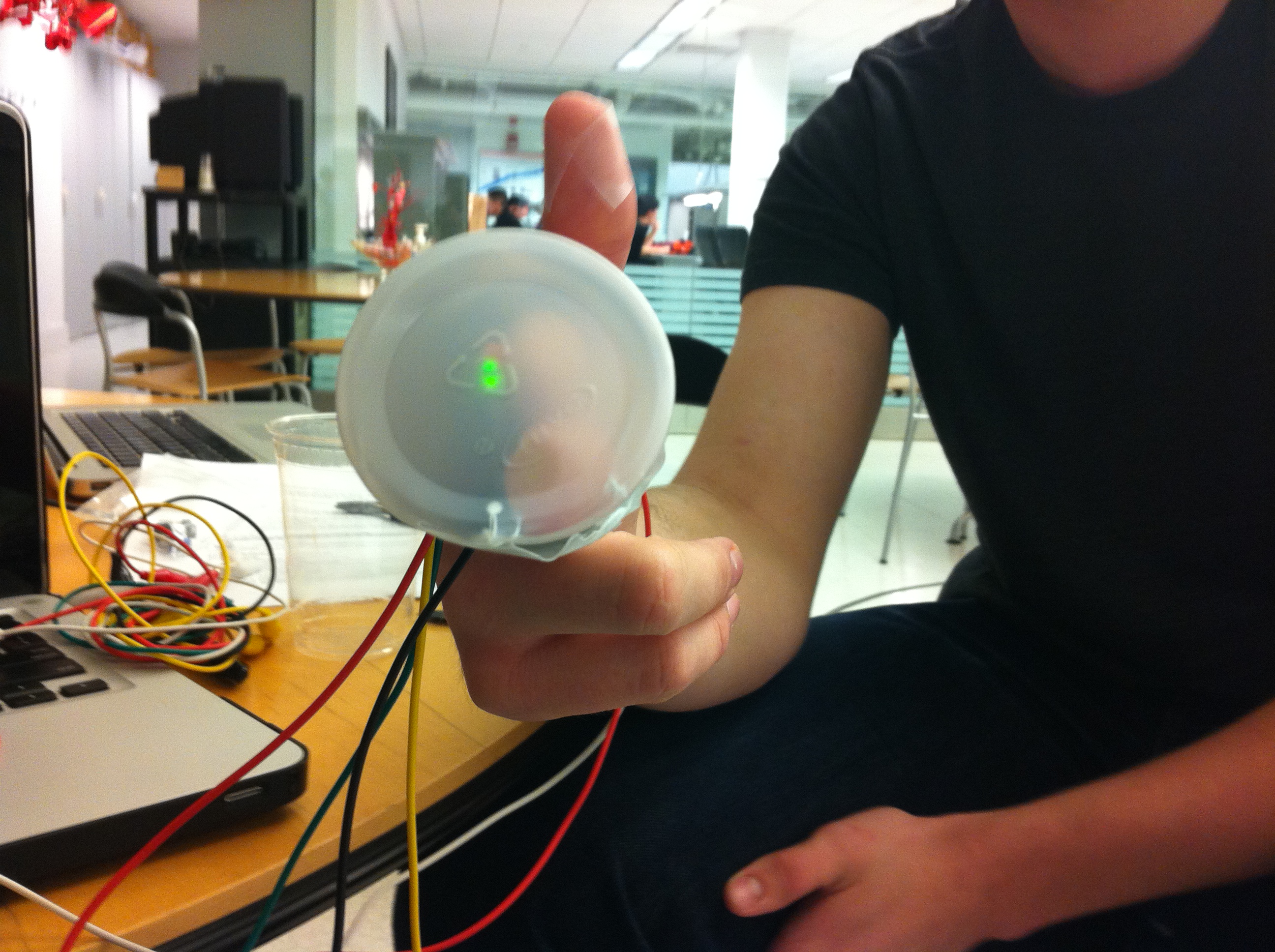
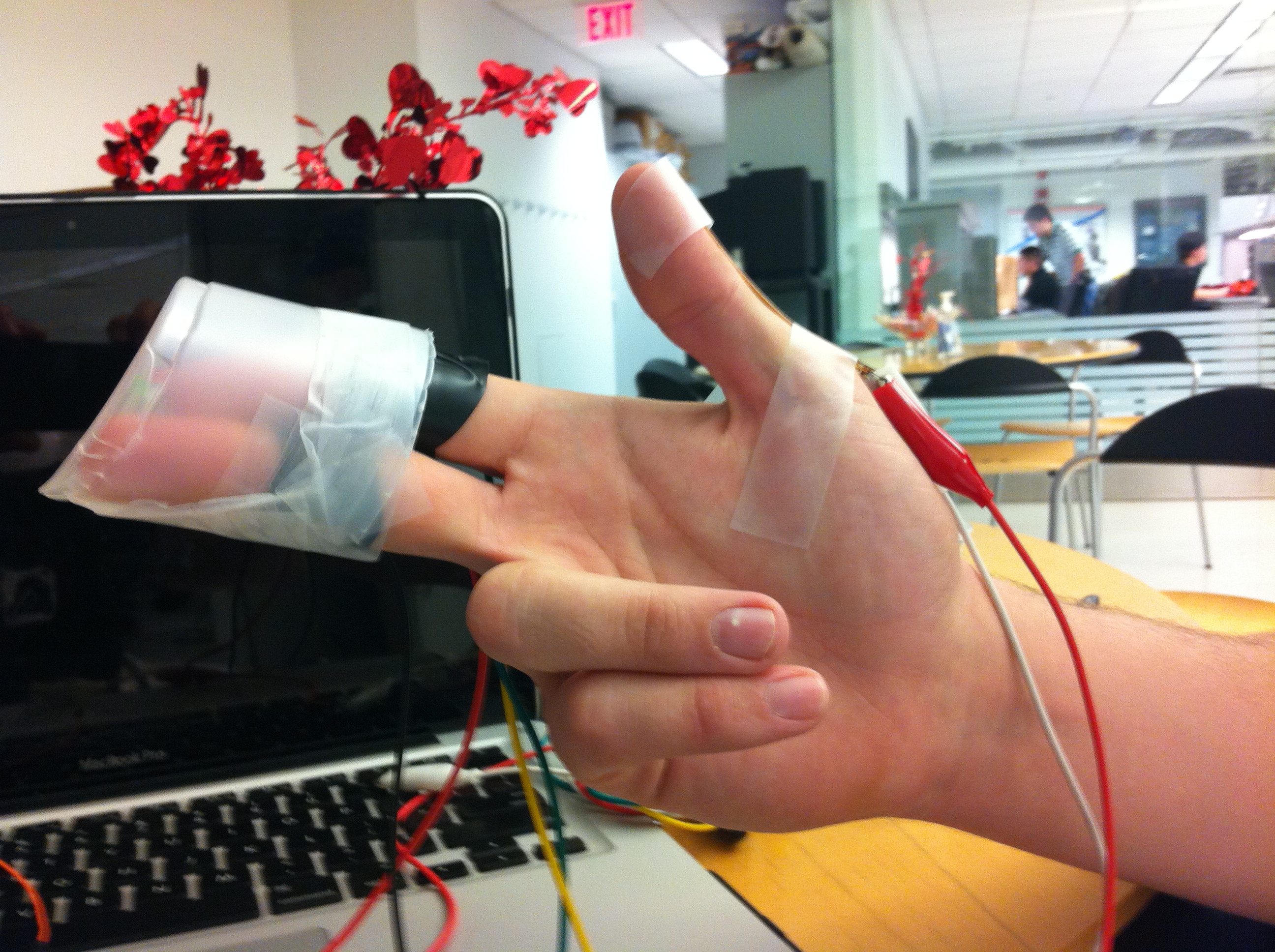
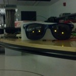
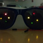
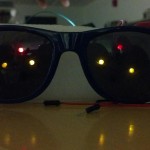
We built a “strongman game” that uses a flex sensor to measure a player’s “digital” strength. As the player flexes the sensor, the amount of flex is categorized into one of five strength levels, and we use three LEDs and a speaker to demonstrate which level has been reached. Within each level, the brightness of the brawniest LED reached is varied with pulse-width modulation to match the player’s exertions. At the lowest level, none of the LEDs are lit and the speaker produces no noise. At the next-lowest level, the green LED lights up. At the middle level, the green and yellow LEDs light up. At the second-highest strength level, the green, yellow, and red LEDs light up. At max strength, all three LEDs light up and celebratory music plays from the speaker. We chose to build this because we wanted a way to demonstrate our finger-flexing prowess, and the game’s cheerful blinking lights and victory song brightened our day while affirming our digital swole. In general, the project was a success, and we were especially pleased with the jingle. For future improvement we might want to change the kind of sensor being used (for example, a pressure sensor that measures the force from the strike of a comically large hammer) and/or the number of lights and tunes available (and consequently, the number of strength categories available).
Video
Each Strength Level
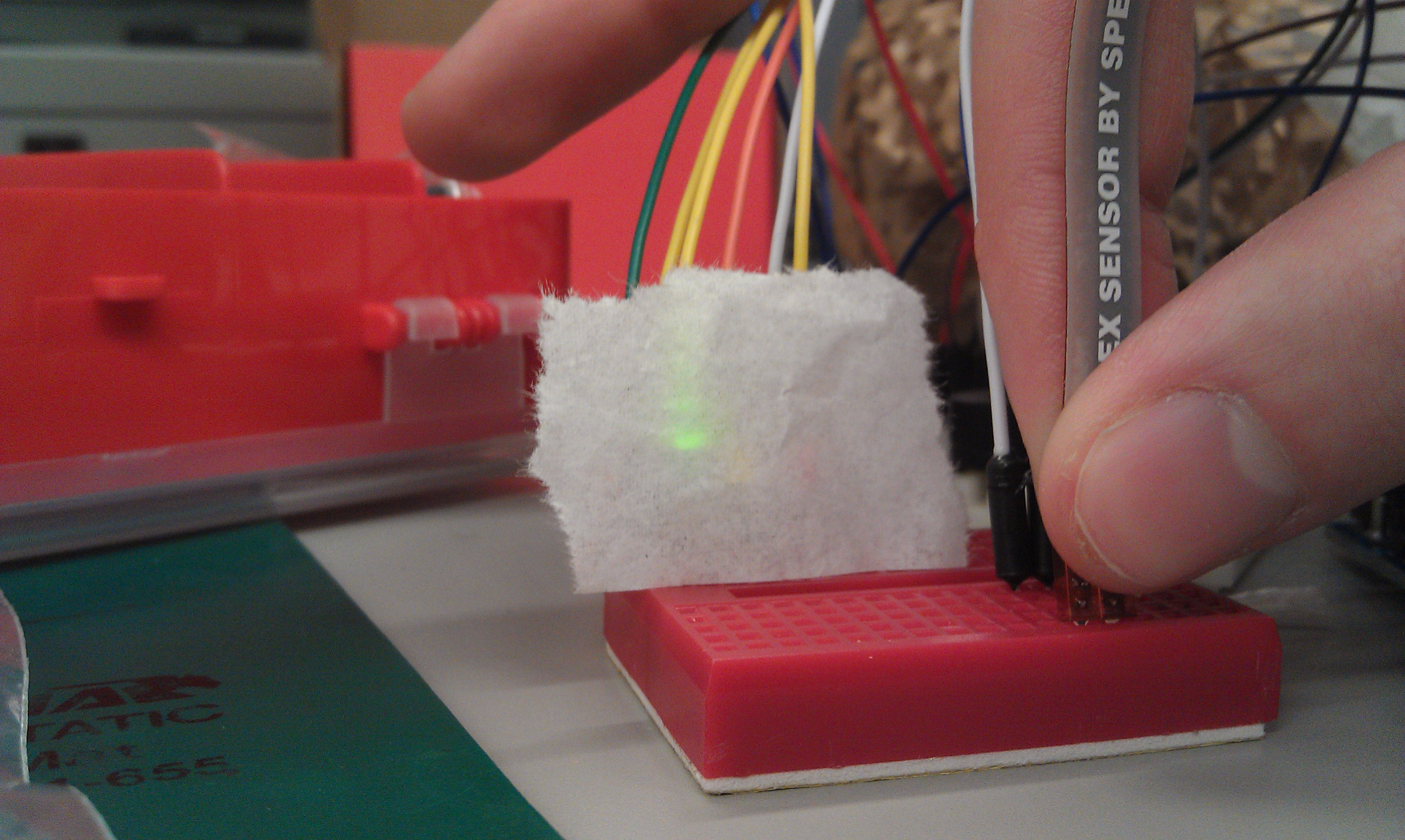
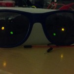
Strength Level One
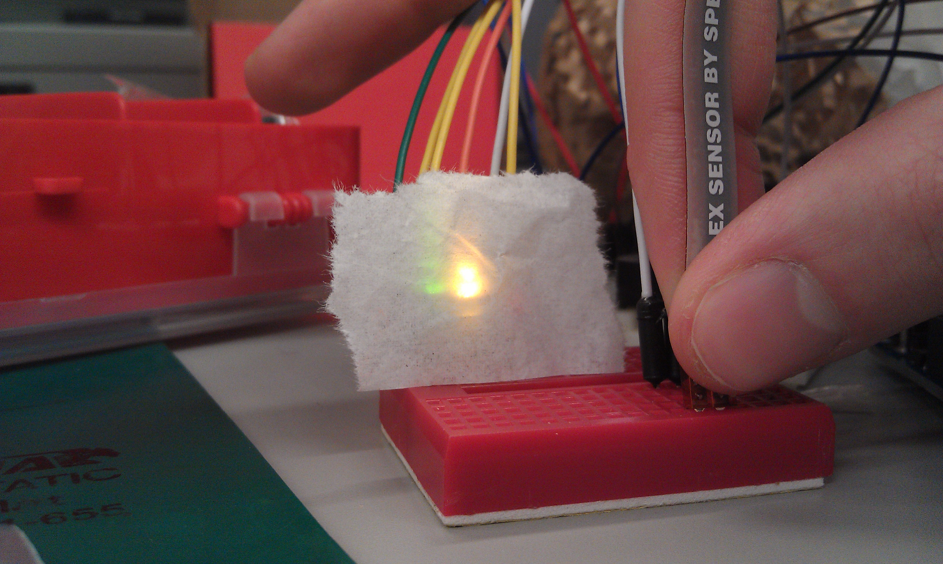
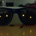
Strength Level Two
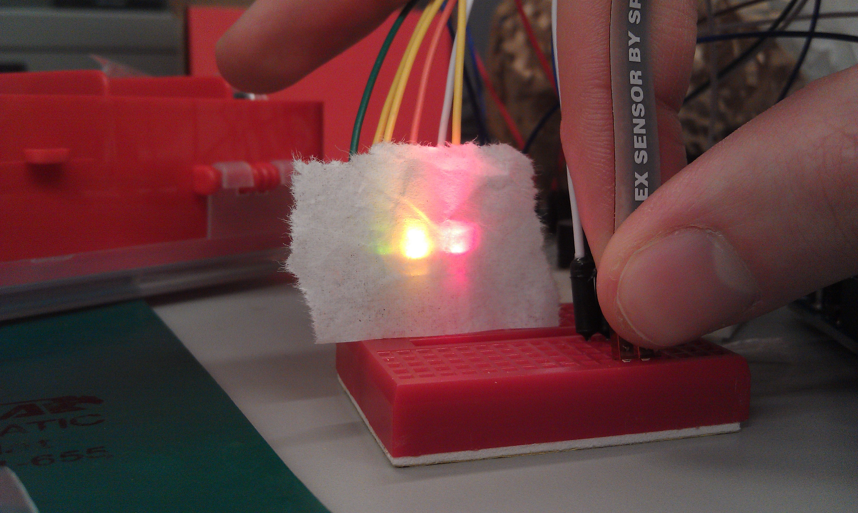
Strength Level Three
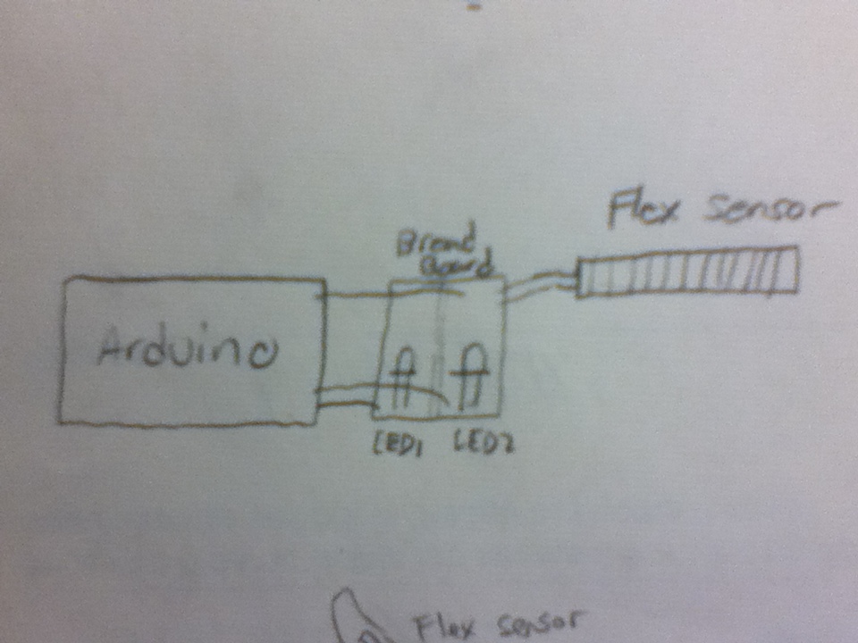
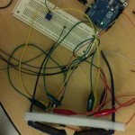
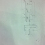
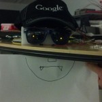
Design Sketches and Final Build
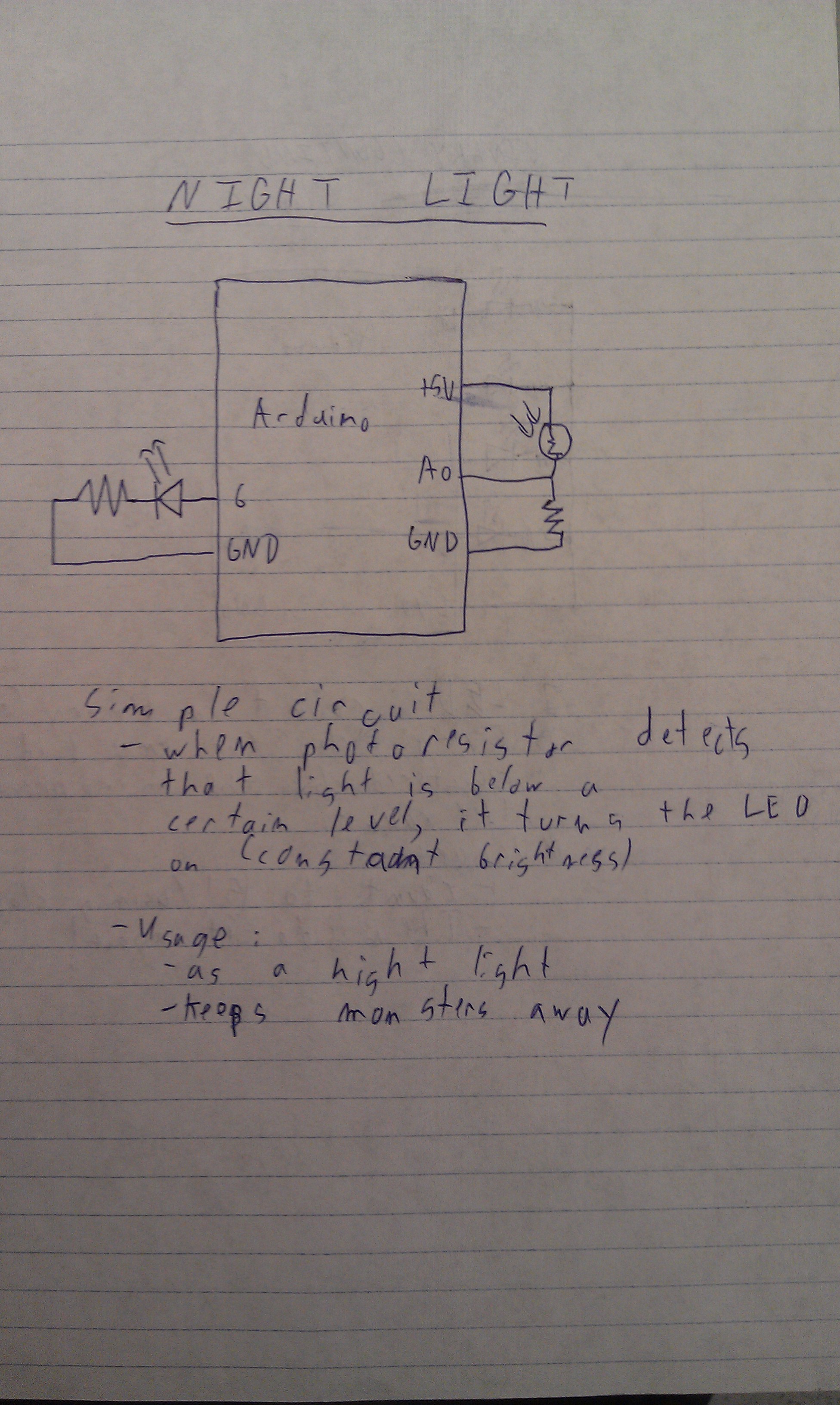
First Design – Night Light
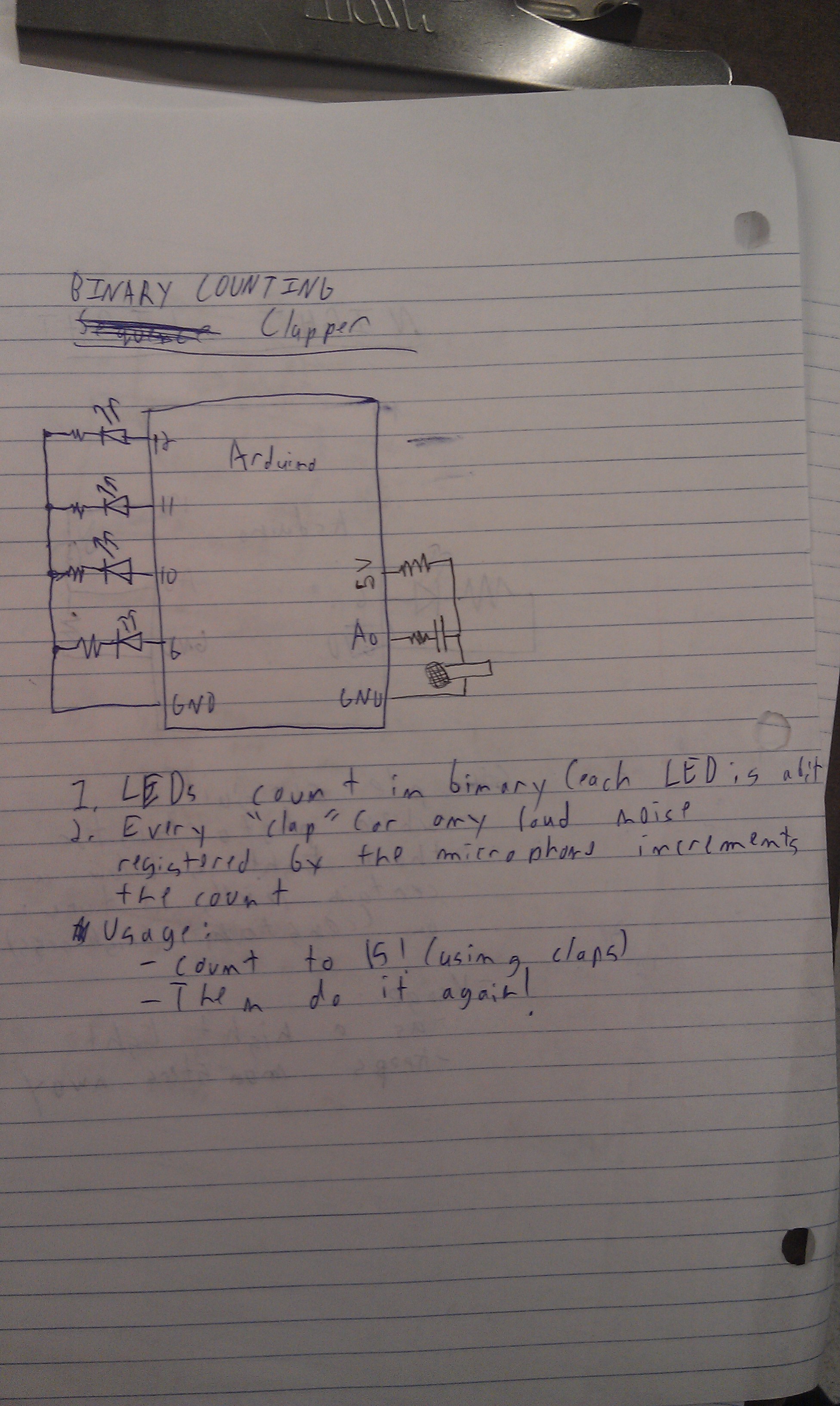
Second Design – Clapping Binary Counter
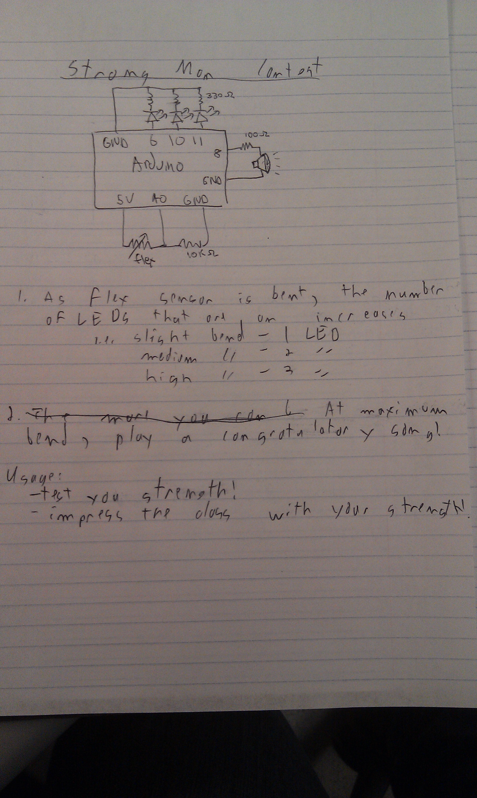
Third Design – Strength Tester

Final Strength Tester Design
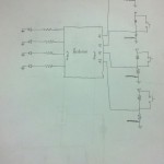
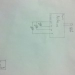
Parts Used
– 3 LEDS (green, yellow, red)
– 1 speaker
– 1 flex resistor
– 1 Arduino
– jumper wires
– 2 breadboards
– 3 330-ohm resistors
– 1 100-ohm resistor
– 1 10k-ohm resistor
– 1 laptop with usb cable
– 1 wax paper diffuser
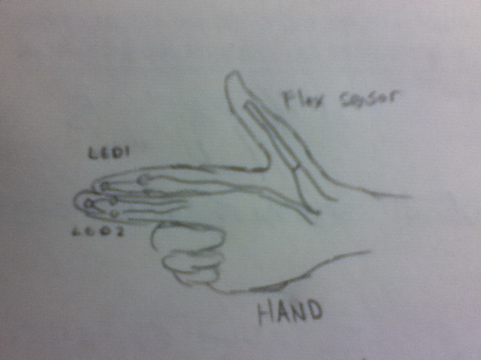
Instructions
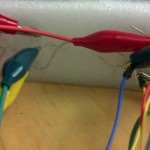
1. Set up the LEDs in a line on a breadboard next to the flex sensor. Place the speaker across the center divider of the other breadboard. You may find it helpful to connect ground and +5V to the power rails of the breadboard for the following steps.
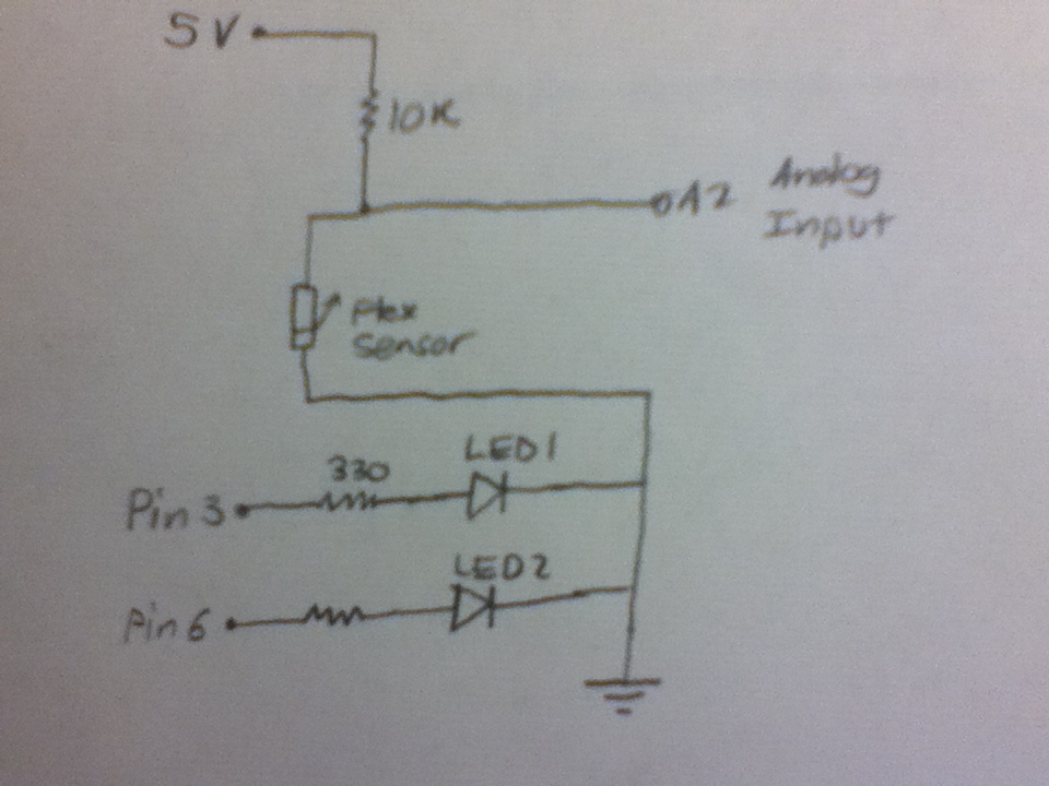
2. Make the following connections:
– Connect the anode of the red LED to pin 6 of the Arduino, the anode of the yellow LED to pin 11, and the anode of the green LED to pin 11.
– Connect the cathode of each LED to ground via a 330 ohm resistor.
– Connect one pin of the speaker to pin 8 and the other to ground via a 100 ohm resistor.
– Connect one side of the flex sensor to a +5V pin.
– Connect the other side both to A0 and to ground via a 10 kilo-ohm resistor.
3. Check the values output by the flex sensor using the serial monitor and the Serial.println() function. In the code, change the FLEX_MAX and FLEX_MIN values as appropriate.
4. Mount the wax paper diffuser in front of the three LEDs.
5. Test your brawn!
Source Code
/*
  Authors: jasnyder, cwhetung, menewman, neilc
  Date: 2/11/2013
  COS 436 Lab L0: The Strength Test

  Test the user's strength with a flex sensor. Display the
  results to LEDs and play them a tune if they are truly
  powerful.
*/
#include "pitches.h"

const int FALSE = 0;
const int TRUE = 1;

//  Input / Output Constants
const int FLEX_MIN = 150;  //  set me as appropriate!
const int FLEX_MAX = 348;  //  set me as appropriate!
const int NUM_STAGES = 6;
const int STAGE_SIZE = ((FLEX_MAX - FLEX_MIN) / NUM_STAGES);
const int ANALOG_MAX = 255;

//  Possible States
const int SONG = 0;
const int ALL_ON = 1;
const int TWO_ON = 2;
const int ONE_ON = 3;
const int ALL_OFF = 4;

//  Musical Constants
const int NOTE_DELAY = 300; // (ms)
const int NOTE_DUR = 250;

//  Pin Connection Constants
const int green = 11;
const int red = 6;
const int yellow = 10;
const int flex = A0;
const int speaker = 8;

//  Variables
int flexvalue = 0;  //  value returned by flex sensor
int stage = 0;  //  current state of LEDs / sensor
int play = 0;  //  have we already played the tune?
int pwmout = 0;  //  dimming value

//  Set internal pull-ups for output on LED pins
void setup()
{
  pinMode(green, OUTPUT);
  pinMode(red, OUTPUT);
  pinMode(yellow, OUTPUT);
}

void loop() {

  //  Grab the bend value and map it to one of the stages
  flexvalue = analogRead(flex);
  stage = map(flexvalue, FLEX_MIN, FLEX_MAX, 0, NUM_STAGES - 1);

  //  Within each stage, dim the "last" LED to the approximate
  //  progression through the stage
  pwmout = (flexvalue - FLEX_MIN) % STAGE_SIZE;
  pwmout = map(pwmout, 0, STAGE_SIZE, 0, ANALOG_MAX);

  //  Turn all LEDS on and play the song once
  if (stage == SONG) {
    digitalWrite(green, HIGH);
    digitalWrite(yellow, HIGH);
    digitalWrite(red, HIGH);

    //  If we have already played the song, do nothing
    if (play == FALSE)
    {
      playACongratulatoryTune();
      play = TRUE;
    }
  }

  //  All on, red variable
  if (stage == ALL_ON) {
    play = FALSE;  //  reset the song
    digitalWrite(green, HIGH);
    digitalWrite(yellow, HIGH);
    analogWrite(red, pwmout);
  }

  //  Green and yellow on, yellow variable
  if (stage == TWO_ON) {
    play = FALSE;
    digitalWrite(green, HIGH);
    analogWrite(yellow, pwmout);
    digitalWrite(red, LOW);
  }

  //  Green on and variable
  if (stage == ONE_ON) {
    play = FALSE;
    analogWrite(green, pwmout);
    digitalWrite(yellow, LOW);
    digitalWrite(red, LOW);
  }

  //  All leds off
  if (stage == ALL_OFF) {
    play = FALSE;
    digitalWrite(green, LOW);
    digitalWrite(yellow, LOW);
    digitalWrite(red, LOW);
  }
}

//  Play a classic little ditty!
void playACongratulatoryTune() {
  tone(speaker, NOTE_G4, NOTE_DUR);
  delay(NOTE_DELAY);
  tone(speaker, NOTE_C5, NOTE_DUR);
  delay(NOTE_DELAY);
  tone(speaker, NOTE_E5, NOTE_DUR);
  delay(NOTE_DELAY);
  tone(speaker, NOTE_G5, NOTE_DUR);
  delay(NOTE_DELAY*2);
  tone(speaker, NOTE_E5, NOTE_DUR);
  delay(NOTE_DELAY);
  tone(speaker, NOTE_G5, NOTE_DUR*4);
  delay(NOTE_DELAY*5);
}