Group 15 : P5 Working Prototype

Group 15 – Lifehackers

Prakhar Agarwal, Colleen Carroll, Gabriel Chen

Project Summary:

Our project is a glove that allows us to control (simulated) phone actions by sensing various hand gestures.

Tasks Supported:

The first and easiest task we implemented is picking up a phone call. A user simply puts his hand into the shape of a phone to pick up a call and then can do the ‘okay’ hand motion in order to end the call. Our second task is more difficult as there are more commands and gestures to be recognized. This task allows users to control a music player with the glove. By using a preset set of hand motions, a user can play and pause music, navigate between a number of tracks and adjust the volume of the music that is playing. Finally, our last task involved allowing users to set a custom password represented by a series of three custom hand gestures, which the user can then use to unlock his phone. This is the most difficult task as it involves setting gestures oneself.

Task Changes:

For the most part, our tasks have stayed the same as they were in the lo-fi prototyping stage. From talking to users during testing, we found that these seemed to be among the simple functions that users would like to be able to control while walking outside in the cold with gloves. Also, these three tasks gave us a nice range of implementation and usability difficulty to play with. One change we did make was setting the number of gestures required for a password to three. We found that allowing the user to add more gestures made both implementation and usability for the end user more confusing.

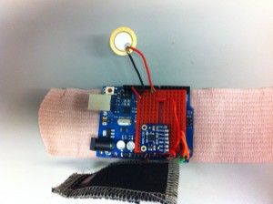
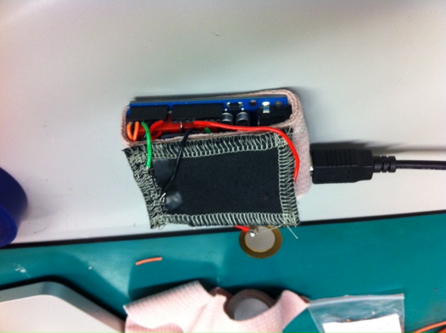
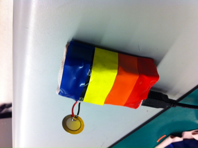
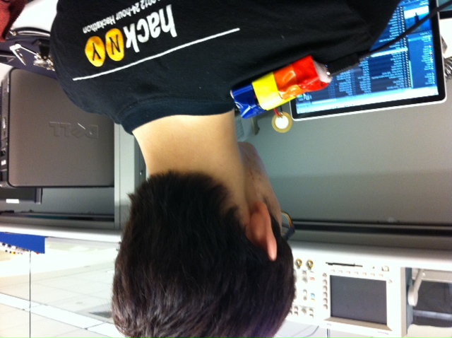
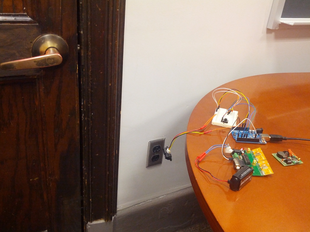
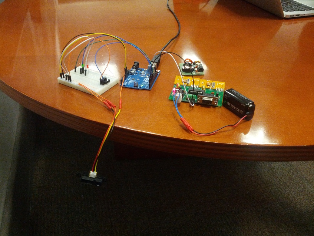
photos of the working prototype:

This slideshow requires JavaScript.

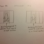
Revised Interface Design:

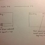
We decided to make a number of changes to our system based on feedback from P4. We decided to put the flex sensors on the back of the glove rather than in the palm. During P4, we found that finger flexibility was a problem for some users because the cardboard “sensors” limited range of motion; this proved to be even more of a problem when we  used the real sensor which came with an additional mess of wires, and so we decided to change our design slightly. Of course, these physical changes also mean that a number of the gestures we had previously proposed changed. The updated gestures for in built functions are shown below:

This slideshow requires JavaScript.

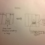
We also imagine that the glove would in the future be wireless and the hardware would be small and secure enough to fit on the glove. In this iteration, we decided not to have an accelerometer on the glove. We found that there was enough flexibility in the number and types of gestures that we could make without one, and adding the accelerometer made the glove very clunky and difficult to use. For future iterations, we have considered using the built in accelerometer in smartphones to add to the variety of gestures that can be issued with the glove. Even our built in gestures could have motion (as pictured below).  We also have one task that we left off of this project, but was in our original plan, the voice command. This gesture, which we imagine to be a “V” with the index finger and middle finger (as pictured below) would initiate the voice command on the smartphone so that a user has access to tasks such as sending texts,making a call, or setting reminders, without having to take off the gloves.

sketches of unimplemented features:

This slideshow requires JavaScript.


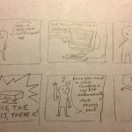
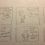
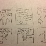
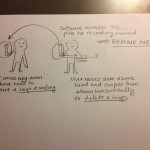
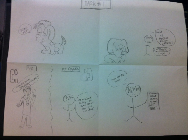
Below are the new storyboards that we picture for the three tasks implemented:

story board for picking up phone:

This slideshow requires JavaScript.

story board for playing music:

This slideshow requires JavaScript.

story board for unlocking phone:


This slideshow requires JavaScript.


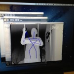
New Prototype Description:

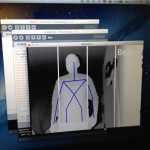
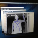
We decided to implement all three tasks on mockup apps made through Processing. The recognition of gestures results in transitions between screenshots, which represent what would happen on an actual phone. Controlling calls and the unlocking process on one’s phone requires jailbreaking of a phone and hacking into its native functionality. This is possible (as seen by the existence of iPhone applications such as CallController which uses the accelerometer to control calls) but potentially dangerous to the phone if incorrectly implemented. So for the sake of the being able to instead concentrate on the user-interface, as opposed to details of the demo app, we implemented the program for desktop.

Using separate sketches in Processing, we implemented each of the three tasks described above. The phone call sketch has implemented functionality for answering and hanging up a call.

video of picking up a phone call:


The music playing sketch has implemented functionality for transitioning between songs, changing volume, pausing, and playing.

video of playing music:


The password setting and unlocking sketches have implemented functionality for setting a 3-gesture password, as well as method for recognition of the password.

 video of setting a password:


video of unlocking phone:


The functionality that we did not implement in this prototype include the accelerometer and the voice command. The accelerometer was left out because it made the glove too clunky and was unnecessary, as explained above. The voice command was left out because, though it was useful, we found that it was one of the least complicated, and we would like to make sure that the more difficult tasks were possible as proof that our entire concept would work. In addition, with the voice command, the issue of user interface primarily falls on the voice recognition software in the phone, as opposed to our glove.

Each task in our prototype works without the aid of a wizard of oz. For now, to go to a different task, a wizard must run the right sketch in Processing. Though we have minimal human interference, our prototype is not a fully functional smartphone app. As stated above, neither Android nor iOS allow a 3rd party app to access functions like answering a call, probably because the app could break that feature if it is built incorrectly. However, we could still imagine the program being issued by the makers of the various smartphone OS’s as a built in tool, much like voice is currently.

Here is a link to all our code: https://www.dropbox.com/sh/b6mnt5mg4vafvag/yIBTTAcZ6t. We referenced Processing tutorials for making buttons: http://forum.processing.org/topic/simple-button-tutorial, as well as Processing tutorials for connecting to Arduino.

P5 – PostureParrot

Group 7, Team Colonial

David, John, Horia

Project Summary

The PostureParrot helps users maintain good back posture while sitting.

Working Prototype Tasks

Task 1 (Easy): Putting the posture parrot on

At this point, the PostureParrot is connected to a USB port for power.  The user puts the connected device onto the top of their shoulder of choice.  The device will stick due to its adhesive underside.

Task 2 (Medium): Setting the default posture

The user should position himself so that he has good back posture.  Then he should press the top of the device.  This will set the default back posture.

Task 3 (Hard): Adjusting back posture based on device feedback

After the user has set a default back posture, the device will make a noise when the user deviates too far from it.  The user must correct their back posture back to the default to make the noise stop.

Choice of Tasks 

The goals of these three tasks are the same as in P4.  However, there are a few differences in how a user must accomplish these goals.  For example, in task 1 the user must put the device on differently due to its new design.  In task 2, the user now sets the default back posture through the button that covers the entire top of the device, a simpler design that prevents the user from having to open an application.  In task 3, the user still reacts to the feedback given by the device, but this time it is done through the sound given off by the PostureParrot, not a vibration.  In general, our adjustment of tasks was driven by the simplification of our product, which eliminated the need for a desktop application.

Revised Interface Design

As a result of P4, we made several changes to how the device is worn. We originally constructed a device that traveled the length of the spine and registered whether or not the user changed his or her posture through a change in flexible, resistive fabrics. One problem with this original design is that it could not accommodate users with extremely small or large back sizes, which we discovered during our paper prototype phase. Additionally, we found that our resistive fabrics were insufficient for creating our device, so we were left in a position that required us to entirely rethink our approach to the problem. Our revised, alternative solution uses an accelerometer to detect changes in posture, and rather than notifying users with a vibrating motor, we decided to notify them auditorily through a piezo buzzer, which requires significantly less weight. This device is placed on the user’s shoulder, rather than the user’s back, and thus accommodates for a wider range of user body types.

Another alteration we made for our revised interface was to remove the data visualization GUI that displayed back posture deviance over time. Through our user tests, we found that plotting the deviance in posture over time and differentiating areas of the back were not contributing a great deal of useful information, and that the benefits of having the device beep was sufficient for notifying the user of poor posture. Through this simplification process, we lost a way for the user to set their default back posture; to account for this, we embedded a reset button in the device itself that provided the same functionality. Overall, these various changes allowed for a more simplified device that could accommodate a wider breadth of users.

IMG_20130422_222927.149 IMG_20130422_222950.566 IMG_20130422_223009.010 IMG_20130422_223026.616

Overview and Discussion

The implemented functionality is displayed in Video #1 below.  The user can attach the device to a shoulder of their choice, press the top of the device to set a default posture and then reap the benefits of automatic feedback during back posture deviations.  The user can always set a new default back posture by pressing the top of the device.  In Image #1 you can see the accelerometer and piezo sensor, providing posture input and sound output respectively.  In Image #4 you can see the final prototype, complete with colorful tape.  A “user” wears the PostureParrot of their choice in Image #5.

In order to make our prototype work, we needed to attach tape to the bottom of the device so that it would stick to the user’s shoulder.  Hopefully, this can be replaced with a more permanent solution in the future.  Additionally, we would like to make the PostureParrot a wireless product.  Currently, our battery options would more than double the weight of the device.  We’re going to have to do more research to find a good solution for power if we want to get rid of the need for a USB cable.

To connect the analog textile press button, we modeled some of our code off of a tutorial from plugandwear.com, where we purchased the button.  The code is posted below.

int softPot = 0; // this line selects the input pin a0 for the sensor
int ledPin = 13; // this line selects the pin 13 for the LED output
int tempPot = 0; // variable to store the value coming from the sensor

void setup() {
  // this line declares the ledPin as an OUTPUT:
  pinMode(ledPin, OUTPUT); 
}

void loop() {
  // read the value from the soft potentiometer
  tempPot = analogRead(softPot);   
  // it turns the LED on
  digitalWrite(ledPin, HIGH); 
  // stop the program for  milliseconds:
  delay(tempPot);         
  // turn the LED off:       
  digitalWrite(ledPin, LOW);  
  // stop the program for for  milliseconds:
  delay(tempPot);                 
}


Video and Images

Video #1 (A video of a user completing all three tasks.  Listen carefully for PostureParrot feedback.)

PostureParrotM4V

Image #1

photo 1

Underlying circuitry, including an arduino, accelerometer, piezo sensor, textile analog pressure sensor and wiring.

Image #2

photo 2

Circuitry enclosed by elastic wrap and textile sensor.

Image #3

photo 3

Device wrapped in colorful electric tape.

Image #4

photo 4

PostureParrot on the left shoulder of a “user”.

P5 – Cereal Killers (Team 24)

Cereal Killers, Group 24

Bereket, Andrew, Ryan, Lauren

We are making a gesture bracelet to do computer shortcuts.


Tasks:

We continued with our three tasks from last time, with modifications based on our testing in P4:

1. Controlling computer hooked up to TV without having to get up

This task is our easiest, and has a person using the gesture bracelet to control a video stream on their laptop hooked up to a TV.  They can do things such as pause, play, and adjust volume.

2.  Using online recipe while cooking

This our our medium task.  It requires the user to use an online recipe and do things such as zoom and scroll up and down while they are cooking and their hands are occupied and /or dirty.  The gesture bracelet prevent the laptop from getting dirty and makes the experience easier for the experimenting cook, who may be cooking for a family or a group of roommates.

3.  Assisting an injured person to aide their computing experience

This is our hard task, primarily because of the challenge for the user to pick useful shortcuts.  The injured user (who can otherwise only use one hand) uses the bracelet to do things such as hold the shift key when typing, scroll through pages, and go back and forward on their web browser.

Our tasks did not change.  Instead, aspects of them were adjusted to incorporate revisions to the feature bracelet.  We felt that our tasks did a good job or targeting users, and based on our user tests, users agreed.

Revised Interface:

We decided to change our interface for two main features.  First, we realized from user testing that users often had trouble coming up with gestures, so we made predefined gestures that they can choose from.  We also added shaking the bracelet quickly, side to side before use to start and stop a gesture.  This was done so that we would have an easier time recognizing gestures instead of having to look for them at all times.

Each tasks is storyboarded below and updated to include our revisions:

Task 1 part 1

Task 1 part 1

Task 1 part 2/2

Task 1 part 2/2

Task 2 part 1 of 2

Task 2 part 1 of 2


Task 2 part 2

Task 2 part 2

Task 3 part 1

Task 3 part 1

Task 3 part 2

Task 3 part 2

As can be seen, we added a list of prerecorded gestures that the user can choose from.  This will be added for our final version.

New Prototype:

We implemented keyboard and mouse recording and playback.  We can have a user input a keyboard sequence and map it to a gesture, or input a mouse click sequence and map it to a gesture.  Videos are added below.  Right now, the sequences work for windows only, but we hope to have it implemented on all operating systems eventually.

We also made a gui for the program.  It is a template for our program, and we will run our code through it for the final project.  The gui is pictured below.

We left out gesture recognition for our prototype.  We did this since we could easily do a wizard-of-oz recognition and still get good feedback from users without having it.  Meaning, we will have a group member type in a number to the terminal when the user does a gesture to trigger the matching computer shortcut. Our gui is also not perfected, so we will use a command line interface for user testing.  We could then incorporate (simulate) all of the functionality of the system, and have it be believable and close to how it would actually perform for user testing.  Obviously, we were time constrained, so we focused our efforts on recording keyboard and mouse input, and outputting them, and making a believable system for user testing.  We were able to get data from the bracelet to python where we will do the gesture recognition, and we will work on having this and our full gui ready for our final demonstration.

The external libraries we used were pyHook, pywin32, and autopy.

 Video/Images:

Logging computer input:

Emulating user output:


Gui

Gui Main Menu

screen2

P5: AcaKinect

I. Your group number and name

Group 25 – Deep Thought

 II. First names of everyone in your group

Neil Chatterjee Harvest Zhang Vivian Qu Alan Thorne

III. 1-sentence project summary 

AcaKinect is a voice recording software using the Kinect for gesture-based control, which allows the music users to record multiple loops and beat sequences and organize them into four sections on the screen, giving the users an more efficient and intuitive music recording interface.

IV. 1 paragraph describing 3 tasks you have chosen to support in this working prototype 

The first task (easy) is to create a simple one-track loops using gestures, by raising one hand above the head. This creates a loop in one of the four sections of the recorded voice. The second task (medium) is to create multiple loops in different sections of the screen, and even multiple loops in one section of the screen using the same gesture from the first task. The user does this by repeating the first task in the same and in different sections. The tracks will all loop over each other. The third task (hard) is to complete the second task with the addition of deleting tracks, by raising one arm and pointing the other arm to the elbow and swiping outward. This is the first part towards the creation of a fully editable sequencing and recording system.

 V. 1 short paragraph discussing how your choice of tasks has changed from P3 and P4, if at all, as well as the rationale for changing or not changing the set of tasks from your earlier work.

We have scaled back the set of tasks from P3 and P4. For our paper prototype we wanted to make sure that users could do everything the software had to offer. For this prototype we wanted to ensure that our core functionality worked properly. We put off implementing a master recording functionality in order to enable track deletion. The music recording process is more expressive and customizable if the users are able to delete tracks: we wanted our prototype to reflect that. We also have had some difficulty implementing a master track and so we could not include it in our tasks for now. In our paper prototype, we also had a “settings menu” where you could adjust the overall recording volume and EQ. Since this wasn’t essential to creating a minimum working prototype, we didn’t include it since it added additional complexities we would have to manage. We hope to be able to fully implement all the functionalities in our paper prototype by our final demo.

VI. 2–3 paragraphs discussing your revised interface design

We changed the display of the beat count (for a total of 8 beat loops) from a timing bar at the bottom of the screen, to simply print out a beat count. This was easier to implement and may actually be simpler for the user to understand. We will find out during the prototype testing how helpful this format of displaying the beat count is. We were also unable to get the section panels to successfully display transparency, so we changed the display to instead show a bar at the bottom of the section which the user are standing in.

From our own preliminary testing, we found that the Kinect is extremely sensitive in terms of gesture detection. So our “delete track” (raise one arm and swipe other arm) gesture often gets mistaken for a “start loop recording” (raise one arm) gesture since both involve raising a single arm. The beginning of the delete motion could start recording unintentionally. We plan on eliminating the gesture overlap, and make them clearly different. We have not yet implemented this change, but expect to before user testing on the hi-fi prototype.

Additionally, the GUI is incomplete. Currently, we are relying on the depth image from the Kinect to show the figures on the screen. In our paper prototype, we had a simple body outline which showed the person on the screen. Ideally, we would do something similar for our hi-fi prototype and outline the bodies of the users using OpenGL/Box2d to create a clean, simple interface. Adding color would be awesome too. See Section VIII for an attempt at creating a better UI — we were unable to get the timing for the beats exactly right, so we delayed implementing the better UI for the final demos. One important part of the UI which we have not yet implemented is displaying a rectangle in each panel corresponding to the loops which the user has recorded. This was due to some difficulties managing the visualization in Processing. We hope to add this in the upcoming weeks.

Storyboards:

Sketches for the still-unimplemented parts of the system:

VII. 3–4 paragraphs providing an overview and discussion of your new prototype

We have implemented the following functionality:

  • Visually track user using Kinect skeleton data
  • Built gesture-based functionalities for recording multiple loop, deleting a loop
  • Bring down the sound recording latency to a manageable level
  • Heads up beat/recording status display

The main thing we learned from the paper prototype testing was that the sound playback of the recorded loops was essential for the user to understand and fully utilize the system, which is why we focused on loop recording instead of the master recording for the hi-fi prototype. To have accurate and good sound playback, we needed to display to the user the number of beats per loop. We did this by printing out a beat count using text in the upper right hand corner (See Section VIII). In addition, we wanted to add visual indicators when the loop recording was about to start, during the recording, and when it finished. To do so, we displayed messages in the upper left hand corner — “get ready…” when the loop recording was about to start, “recording” when the loop is recording, and no message when the recording is finished.

We left out the following features: master track recording, and a settings menu. As a reminder, the master recording would be able to combine all the repeating loops that are playing back on screen plus any additional sound that the user adds during the recording time, and save to a single track. We weren’t able to implement this because it requires further investigation. It is not essential for a minimum working prototype. From paper prototype testing, we found that users got confused between “master track recordings” and “loop recordings,” so we decided to prioritize loop recordings in our working prototype and eliminate the confusion for the users. We aim to successfully add this master track functionality later (without confusing the user). For the settings menu, again the EQ and sound level adjustment is not part of the core functionality, so we are saving it until the more important parts work.

Wizard-of-oz techniques: We’re pretending that the master recording is working properly when in fact it is not yet. Our current plan of action is for users to use their imaginations to pretend it is recording. We may also use paper indicators (with text like “Master Track is recording…”) to help users understand, and test out the best ways to signal the users between loop and master track recordings. We implemented functionalities in order of importance to the main use of the software. We ranked the priorities: 1) get loop recording working and synchronized, with sound playback; 2) loop deletion; 3) show user position on screen; 4) show beat count and recording status. Todo: UI improvements (body outline and loop track blocks) and non-implemented functionalities (master recording and settings menu).

External Code and Libraries Used:

  • Minim Library (sound recording and processing)
  • SimpleOpenNI framework for reading in Kinect data (and Skeleton library)
  • For body outline and improved UI (not fully functional): followed the Kinect Physics Tutorial for the body outline, which utilizes the blobDetection, toxiclibs, PBox2D, and org.jbox2d libraries which are all freely available on the Internet.

VIII. Video & Images of Working Prototype

Videos:

A demo of our working prototype.

The non-functioning improved UI. Including in the openGL and polygon drawing libraries for drawing the figure caused additional latency (the beat count was not consistent, sped up during beats 2 and 3 and 5 and 6; this is really bad, since musicians need very constant tempo). We will try and work out the bug for this in the future so we can use this cool UI!

Photos:

P5: Dohan Yucht Cheong Saha

Group # 21 : Dohan Yucht Cheong Saha


  • David Dohan

  • Miles Yucht

  • Andrew Cheong

  • Shubhro Saha


Oz authenticates individuals into computer systems using sequences of basic hand gestures.


Tasks Supported


Our easiest task is the profile selection for the users. To confirm a user’s “username” he or she will select an image from a gallery of profiles that corresponds to him/herself. The medium-difficulty task is handshake parsing, during which our system detects whether the pass-gesture is correct. The final, and most intricate, task is password reset– which involves sending an email to the user for a handshake reset link. In addition, training the system is an additional task we’re adding to this prototype. The user must perform a series of gestures to have our system recognize their hand with accuracy.


How Tasks Changed


One of our prior tasks was to detect the face of a user; however, this task’s purpose was to identify the “username” of the individual which was covered by the profile selection task. Since these two tasks have identical functionality, there was not immediate need for both. Having facial recognition would be an interesting task that could be implement in the future. Instead, we realized that procuring training data on the hand gestures is a more significant task that dictates the effectiveness of detecting hand gestures. We also did not incorporate password recovery (yet) because its purpose is not crucial to the functionality of Oz, but is in the pipeline.


Revised Interface Design


We decided to move away from the Leap Motion technology and are using a web camera to detect hand gestures. Some motivations for this change includes stepping away from a black-box technology and the ease of using openCV and scikit-learn with webcam data.  We found overall that our webcam based approach gave a higher accuracy than the Leap Motion.


As a result of our change in hardware type (Leap to webcam), we found that we must approach the box design very differently.  The Leap does not need light in order to function, as it has IR LEDs built in.  For our webcam, however, we both need a larger box and must install lights in our box.  For the first functional prototype, we elected to simply use a large, open box with the webcam mounted at the top.  Because the box is not sealed and is a similar color to skin, our first prototype also requires that the user wears a black glove so their hand can be differentiated from the background.  In the future, the inside of the box will be black, so no glove will be necessary.


Updated Task Storyboard


Sketches for Unimplemented Features


Overview & Discussion of New Prototype


In this prototype, we have advanced our previous prototype by turning the paper model into one that the user interacts with on the screen. In addition, in the background, we’ve made advanced in our underlying technology by developing the proof-of-concept for hand recognition with a regular webcam. Because we haven’t integrated this proof-of-concept into a browser-based plugin, however, we still require a wizard-of-oz routine to ensure test users have entered their handshake sequence correctly


There are mainly two things we left out of this prototype. The first is the browser plugin that will allow the user to use handshake authentication on a web site like Facebook. We left this out because we need more time to learn about browser plugins and require the back-end system with hand recognition to be complete. The second functionality left out is the integration of the hand-recognition technology that we have completed at an experimental stage (see above). Though the experimental results give us confidence in the proof-of-concept, we have yet to polish the software into something that can be integrated with the browser plugin.


There are two wizard-of-oz techniques required to make the prototype work today. The first is on the user-interface side, where someone needs to press an arrow to proceed the slides. The user can still tap the screen in a touch-screen style interface to proceed. The second wizard-of-oz technique is on the hand recognition side. Though we have a proof-of-concept complete for hand recognition, it has not yet been integrated into the prototype, but may be complete by P6.


We fully implemented the detection of basic hand gestures to demonstrate a proof of concept. We also implemented the training of the hand gestures using the webcam and the APIs explained. Because this training data is necessary for the detection of hand gestures, we implemented this task as well. We believe that these two parts are the most important part of our prototype to implement immediately because they will require the most work to refine.  We must both devise a novel algorithm for classifying hand shapes and provide an intuitive way of training it for use by multiple users.


The two outside code sources that we used were the opencv, numpy (to handle the opencv data structures), and scikit-learn APIs. The opencv API allows us to obtain still images from a webcam, threshold the hand, find the contour of the hand, resize the image to fit the hand, and to save the images to disk. Scikit-learn was used to create a support vector machine object, to train it using data taken from a webcam, and based on the data from the webcam predict the label for the current hand.


Video capturing proof of concept hand recognition:

https://www.dropbox.com/sh/nb91flk0v2fmml4/F7RhHS2sjN/p5?lst#f:classifier.mp4


PDF capturing user-interface screens to use during prototype testing:

https://docs.google.com/file/d/0B9RlBTXdYjXMQlBDXzJwa1ZsbzA/edit?usp=sharing


Proof of Concept Git Repository:

https://github.com/dmrd/oz/tree/master/camera


P5: Group 14 (Team Chewbacca)

Group number and name
Group 14: Team Chewbacca

First names of everyone in your group
Karena, Jean, Stephen, Eugene

Project summary
Our project is a sys­tem con­sist­ing of a bowl, dog col­lar, and mobile app that helps busy own­ers take care of their dog by col­lect­ing and ana­lyz­ing data about the dog’s diet and fit-ness, and option­ally send­ing the owner noti­fi­ca­tions when they should feed or exer­cise their dog.

Tasks supported by prototype

1. Sending diet and activity data to vet
The user will be able to generate a detailed profile using the data collected over extended periods of time using our device, and send this report to their veterinarian. This report, although difficult on the backend to collect the data and send it, should be very easy to the user, and require clicking only a few buttons. This report will be useful for the veterinarian and other caretakers of the dog, to manage the dog’s overall fitness levels.

2. Monitoring diet
The user will be able to check whether or not they need to feed their dog based on when and how much their dog has been fed. Based on this information the user can see if they forgot to feed their dog, and ensure that their dog is not over or undereating. This is a medium-difficulty task for the user, as they might check both the homepage and the “diet” page of the app.

3. Monitoring activity
The user will be able to check whether or not they need to exercise their dog, based on their dog’s recent activity level. More detailed analytics on the dog’s activity level can be viewed real-time over bluetooth connection or with graphs that display long-term data. This is a difficult task for the user, as the user might check three different screens in order to see all of this information (the homepage, the general activity page, and the detailed activity graph page).


Changes in Tasks
We changed our tasks slightly from the previous step, based on our interviews and user feedback that we’ve received. From our understanding, the users wanted to the app to give them direct suggestions based on the collected data, such as whether or not they should feed their dog, or whether or not they should walk their dog at the current moment. Therefore, we made our tasks more directed towards finding information to guide the user’s actions: deciding whether or not to feed your dog, deciding whether to walk your dog, and generating and sharing your dog’s fitness report. In addition, we changed Task 1 from “Export data” (in P4) to “Send data”, as a user who tested our prototype said that they would not use an exported data document for themselves, and found it confusing that this task was for “exporting” when they would only use it for sending reports to the vet.

Discussion

Design Changes from P4
We made several changes to our design as a result of P4.  First, we got rid of the LED and time display on the dog bowl, as two out of the three users who tested our P4 prototype found the LED color display confusing, and these users also said that both the LED and the time display were superfluous (see the first paragraph of the “discussion of results” section of our P4 blog post).  We thought that this change also made our system much more unintrusive, and we want our system to be seamlessly integrated into a user’s normal routine.

In addition, we made several changes to the mobile app interface.  For example, we made the homepage of the mobile app display only suggestions to the user about their dog’s diet and activity (i.e. whether or not they should feed or walk their dog).  We changed this after two of our users in P4 said that they didn’t care about the detailed quantitative data and/or had trouble interpreting it (see the first paragraph of the “discussion of results” section of our P4 blog post).  As a result of this user feedback, we also created “secondary” pages in our app that displayed the most pertinent quantitative information about the dog’s diet and activity, and buttons on these secondary pages that take the user to the more detailed data.  This keeps the app from displaying an overwhelming amount of data to users who do not need it, and overall makes the app more user-friendly. Some other small changes we made to our app were to display the “health score” as a ratio out of 100 (which one of the users in our prototype test suggested), and to make the “export data” page specialized toward only sending the data to a veterinarian.

Storyboards

photo 2 (2) photo 3 (2) photo 4 (2)

Sketches

photo 4 photo 5 photo 3 photo 1 photo 1 (2) photo 2

Overview and discussion

Implemented functionality
We have currently implemented a dog bowl that detects the weight of food/water that is added to it and records the time at which the contents were added, a dog collar with an attached accelerometer that records the number of steps taken, and a mobile app that collects the data from these devices via bluetooth and displays the data in real time.  Currently, the app can display a real-time graph of number of steps taken over time and the total number of steps taken, and the time the bowl was last filled.

Unimplemented Functionality
We left some of the proposed functionality of the complete system out of this prototype.  For example, we left the “diet log” page of the app out of the prototype, as this is not a crucial part of the system and will not be accessed often by actual users.  In addition, the crucial data (time and amount of last feeding) are displayed already on the general activity page, and are sufficient for user testing.  We also did not implement the push notifications telling the user that they need to feed/exercise their dog, as these suggestions are already displayed on the homepage, and this is sufficient for testing.  Finally, we did not implement the settings page that would allow users to customize their experience on the app.  This settings page would also set their preferences for push notifications, i.e. what time they usually feed their dog/how long after this time they wish to be notified, and after what duration of low activity they wish to be notified.  Both the settings page and its interaction with the push notifications are complex for both the user and the back-end implementation, so we decided to leave this until the next stage of development.

Wizard-of-oz techniques
Though the hardware aspects of our project (dog bowl weight sensor and dog collar accelerometer) are currently implemented, we use several wizard-of-oz techniques in our mobile app.  For example, the suggestions displayed on the homepage of the app for whether or not the user should feed or walk their dog only change after the suggestion boxes have been pressed five times.  In the future, these suggestions will change based on the collected data and the deviation of this data from the suggested amounts of food/activity. However, we felt that this implementation still allowed the user to see how they could make decisions based on the suggestions given by the app.

In addition, we use a wizard-of-oz technique for the “send data” page of our app — currently, it allows the user to select options and type the email of their vet, and displays a success notification when the “send” button.  However, nothing is actually sent, and in the future we wish to actually create a document and send it via email.  We felt that the wizard-of-oz technique allowed the user to experience how they would interact with the app when they actually sent data. Finally, the activity graphs shown on the “activity” page of the app is wizard-of-oz, as we currently display graph images that are not updated or based on the actual collected data.  We used wizard-of-oz for this aspect of the app because we are not able to test our system over a long period of time and thus have no long-term data with which to create these graphs.

Code

For Arduino:
MeetAndroid.h library
Time.h library

For Android
From Amarino:
– Amarino libraries
– SensorGraph
– GraphView
– Amarino application to connect to bluetooth
DateFormat library
Date library

Tutorial for Sensor Graph
http://www.bygriz.com/portfolio/sensor-graph/#more-1344

Tutorial for Android Beginners
http://developer.android.com/guide/topics/ui/controls.html

Video and Image Documentation

Demo Video: http://www.youtube.com/edit?ns=1&feature=vm&video_id=jyTRtAOslgg

Screenshot_2013-04-22-21-09-33Screenshot_2013-04-22-21-09-43Screenshot_2013-04-22-22-58-04Screenshot_2013-04-22-21-10-57Screenshot_2013-04-22-21-11-06 Screenshot_2013-04-22-21-09-49 Screenshot_2013-04-22-21-10-30  Screenshot_2013-04-22-22-58-18 Screenshot_2013-04-22-22-58-25

P5 Runway – Team CAKE

Group number and name: #13, Team CAKE
Team members: Connie, Angie, Kiran, Edward

Project Summary

Run­way is a 3D mod­el­ling appli­ca­tion that makes 3D manip­u­la­tion more intu­itive by bring­ing vir­tual objects into the real world, allow­ing nat­ural 3D inter­ac­tion with mod­els using gestures.

Tasks Supported

The tasks cover the fundamentals of navigation in 3D space, as well as 3D painting. The easiest task is translation and rotation of the camera; this allows the user to examine a 3D scene. Once the user can navigate through a scene, they may want to be able to edit it. Thus the second task is object manipulation. This involves object selection, and then translation and rotation of the selected object, thus allowing a user to modify a 3D scene. The third task is 3D painting, allowing users to add colour to objects. In this task, the user enters into a ‘paint mode’ in which they can paint faces various colours using their fingers as a virtual brush.

Task Choice Discussion

From user testing of our low-fi prototype, we found that our tasks were natural and understandable for the goal of 3D modelling with a 3D gestural interface. 3D modelling requires being able to navigate through the 3D space, which is our first task of camera (or view) manipulation. Object selection and manipulation (the second task) are natural functions in editing a 3D scene. Our third task of 3D painting allows an artist to add vibrancy and style to their models. Thus our tasks have remained the same from P4. In fact, most of the insight we gained from P4 was in our gesture choices, and not in the requirements for performing our tasks.

Interface Design

Revised Interface Design

The primary adjustments we made to our design concerned the gestures themselves. From our user tests for P4, we found that vertex manipulation and rotation were rather unintuitive. This, in addition to our discovery that the original implementations would not be robust, prompted us to change the way these gestures worked. We added the space bar to vertex manipulation (hold space to drag the nearest vertex), both to distinguish vertex manipulation and object translation, and to make vertex manipulation more controlled. For rotation, we changed our implementation to something with a more intuitive axis (one stationary fist/pointer acts as the center of rotation), so that the gesture itself is better-defined for the sake of implementation.

Two main features that we added were calibration (elaborated on below) and statuses. The statuses are on-screen text prompts that show data fetched from the leap (e.g. what hand configuration(s) are currently being tracked), the mode, the current color (if relevant), and some debugging information about the mesh and the calibration. These statuses are displayed at screen depth in the four corners, in unassuming white text. They are primarily for information and debugging purposes, and hopefully do not detract from the main display.

Everything else in our design remained largely the same, including the open-handed neutral gesture, pointing gestures for object manipulation and painting, and fists for camera/scene manipulation. We also mapped mode and color changes to keyboard keys somewhat arbitrarily, as this is easy to adjust. Currently, modes are specified by (1) calibration, (2) object manipulation, and (3) painting. Colors are adjusted using triangle brackets to scroll through a predefined list of simple colors. We hope to adjust this further from user testing feedback.

Update Storyboards

Our storyboards have remained the same from P4, since our tasks from P4 are suitable for our system. These storyboards can be found here

Sketches of Unimplemented Features

The two major features that we have not implemented are head tracking and 3rd-person viewing (both of which are hard to sketch but easily described). Head tracking would allow us to adjust the object view such that a user can view the side of the object by simply moving his or her head to the side (within limits). Software for third-person viewing can render the display in its relative 3d space in a video, so that we can demo this project more easily (this is difficult to depict specifically in a sketch because any sketches are already in third-person). Both of these features are described in more detail below.

Prototype Description

Implemented Functionality

Our current prototype provides most of the functionality required for performing our three tasks. The most fundamental task that we did not incorporate into our low-fi prototype was calibration of the gesture space and view space. This was necessary so that the system knows where the user’s hands and fingers are relative to where the 3D scene objects appear to float in front of the user. The calibration process is a simple process that must be completed before any tasks can be performed, and requires the user to place their fingertip exactly in the center of where a target object appears (floating in 3D space) several times. This calibration process is demonstrated in Video A. Once this calibration is completed, a pointer object appears and follows the user’s fingertip. This pointer helps provide feedback for the user, showing that the system is following them correctly. It also helps them if they need to fine-tune the calibration, which we have implemented on a very low level where various keyboard keys change the values of the calibration matrix.

After calibration has been performed, the user can start performing the 3D tasks. As mentioned above, there are three modes in our prototype: View mode, Object Manipulation mode, and Painting mode. In all three of these modes, we allow camera manipulation, including translation and rotation, using fist gestures as described above. Basic camera manipulation is shown in Video B.

In Object Manipulation mode, we support translation and rotation of individual objects in the scene, as well as vertex translations. Translation requires the user to place a single fingertip onto the object to be moved, after which the object would follow the fingertip until the user returns to the neutral hand gesture. Rotation involves first placing one fingertip into the object, and then using the other fingertip to rotate the object around the first fingertip. These operations are shown in Video C. Finally, vertex translation is activated by holding down the spacebar; then, when the user approached suitably close to a vertex on an object, they could drag that vertex to a desired position and release it by releasing the spacebar. Vertex manipulation is shown in Video D.

Finally, the Painting mode allows the user to select a paint color using the keyboard and paint individual faces of a mesh using a pointing fingertip. When a fingertip approaches suitably close to a face on a mesh, that face is painted with the current color. This allows the user to easily paint large swathes of a mesh in arbitrary shapes. This process is shown in Video E.

We implemented these features because they are central to performing our tasks, and we had enough time to implement these features to a reasonable level of usability.

Future Functionality

All of our basic functionality is in place. However, there are several things that should be completed for our final system, mentioned in the previous section.

  • The most important such task from a user standpoint is to add in head tracking. This will allow the user to move their head and see the appropriately differing view of the scene while still maintaining the calibration between viewpoint and gesture. We will accomplish this by using an Augmented Reality toolkit that provides can provide the position and orientation of fiducial markers (which look like barcodes) in a camera frame; attaching a marker to the 3D glasses will allow us to track the user’s head position and therefore viewpoint relative to the monitor. We have not implemented this because the core scene manipulation functionality is more central to our system. Our system works fine without head tracking, as long as the user does not move their head too much.
  • For the purposes of demonstrating our project, we also want to use augmented reality toolkits to allow third-person viewers to see the 3D scene manipulation. Currently, as you can see in first videos, the system looks rather unimpressive from a third-person point of view; only the active user can see that their finger appears in the same 3D location as the pointer. Adding this third-person view would allow us to take videos that show the 3D virtual scene “floating” in space just as the main user would see it. This is also implemented using the Augmented Reality toolkit, which will allow such a third-person camera to know its position relative to the Leap sensor (which we will place at a specified position relative to a fiducial marker on the desk). Since this is clearly for demo purposes, it is not central to the application’s core functionality that is required for user testing.
  • Finally, if we have time we would like to add in an additional hardware component to provide tactile feedback to the user. We have several small vibrating actuators that we can use with an arduino; this will allow us to provide a glove to the user that will vibrate a fingertip when it intersects an object. This would add a whole new dimension to our system, but we want to make sure that our core functionality is already well in place before extending our system like this.
  • Some already implemented parts of our system can also use improvement – for example, several parts of the mesh processing code will likely require optimization for use on larger meshes. Similarly, we can experiment with our handling of Leap sensor data to increase robustness of tracking; for example, some sensing inaccuracies can be seen in the videos below, where an extended fingertip is not detected.

Wizard of Oz techniques

No wizard of oz techniques were used in this prototype. Our system already has all of its basic functionality, so this was not necessary.

External Code

We are building off of the Unity framework as a platform for development, which provides a lot of the basic functionality of an application, input, rendering, and scene management. Conveniently, the Leap Motion SDK provides a Unity extension that allows us to access Leap sensor data from within Unity. We also use the DotNumerics Linear Algebra C# library for some calibration code.

We borrow several classes from the sample Unity code provided with the Leap SDK. Otherwise, the C# Unity scripts are all written by our team. For our unimplemented portions, namely the third-person view and head tracking, we will be using the NYARToolkit C# library for tracking and pose extraction.

Videos

Video A – This video shows the basic setup with stereoscopic 3D monitor and Leap. It also demonstrates the calibration workflow.

Video B – This video shows demonstrates camera manipulations, including how to translate and rotate the scene.

Video C – This video shows object manipulation, including how to select, translate, and rotate objects.

Video D – This video shows vertex translation, where the user can deform the object by selecting and moving a vertex on the mesh.

Video E – This video shows 3D painting, where the user can easily paint faces on the mesh using gestures.

Biblio-File P5

a. Group num­ber and name

Group num­ber: 18
Group name: %eiip

b. Mem­ber names

Erica (eportnoy@), Mario (mmcgil@), Bon­nie (bmeisenm@), Valya (vbarboy@)

c. Project summary

Our project is a smart book­shelf sys­tem that keeps track of which books are in it. You can see the web application portion of our project here!

d. Tasks we have chosen to support in the working prototype

Our hard task is adding an existing book collection to the system; this should consist of at least three books for testing purposes. This is the first task a user would have to complete with our system, and it consists of adding RFID tags to the books, adding them to the system using our mobile interface, and then placing the books on the shelf.

Our medium task is adding a single new book to the system; this is very similar to the previous task. It consists of using the mobile interface and an RFID tag to add a book to the bookshelf.

The easy task is finding a book on the shelf, or searching for a book that is not present. Users can choose to use our mobile app to search for a book, or they may attempt to manually search the shelf. If our system provides added value, we hope that they will opt to consult our mobile app.

e. Differences from P3 and P4

Our tasks have not changed from P3 to P4, though the interfaces the user will interact with and the workflows have changed somewhat. This is because our tasks are goal-oriented, and we believe that the goals of the system remain unchanged. Additionally, the hard task is the first task that an actual user would have to perform, so we believe that testing the proposed tasks in the order given is valuable.

f. Revised interface design

i. Changes as a result of P4 and the rationale behind these changes

The main feedback we received from our user testing was that it takes too long to add a book. In order to fix this we removed the screens that asked our users to verify the information, and we no longer require our users to photograph the cover. Instead, we now have them sim­ply scan the bar­code and we use the Google­Books API on our end to get the rel­e­vant infor­ma­tion. We also noticed that many users struggle with adding a book to the system. We fixed this by adding a clear, obvious, and noticeable “Add Book” button to the main page. In user tests, users also did not use our search feature because they could see all the books on one screen. In our high-fidelity pro­to­type, we utilized mobile design heuristics in cre­at­ing a page with large text and images. A consequence of this is that fewer books are shown at a time, and the user is able to search via predictive queries, implemented using a typeahead.

From the hardware side of things, we initially wanted to use Seeed Studio RFID readers placed behind the bookshelves to statically sense the presence of multiple books, and thereby be able to inventory the contents of the shelf. Users prefered this method to a “tap-in, tap-out” approach to managing books. However, it looks like we may have to take the “tap-in, tap-out” approach since a fundamental limitation of the readers’ hardware seems to be that they can only read one tag at a time. This means that the user will have to tap each book to the scanner when replacing or removing a book.

ii. Updated storyboards 

This storyboard illustrates our most difficult task – adding an entire collection to the system.

Here we illustrate our moderate task – adding one new book to the system.

Finally, here is our easy task – retrieving a book from the bookshelf.

iii. Sketches

Our new bookshelf will have a “tap-in, tap-out” system for adding books, because the RFID scanners are not good enough to simply sense what books are on/off the shelf.

g. Overview and discussion of the new prototype

i. Implemented functionality

In this new prototype we greatly improved the book-adding paradigm. Now, instead of having to go through multiple screens and steps, a user simply takes a picture of the ISBN, puts a sticker or bookmark in the book, and places the book on the shelf. We also implemented a search function, where the users can search by author or title.  We have added “Light Up” buttons to light the shelf the book is on (although the physical light is still done via wizard-of-oz techniques, as explained in more detail below). We provide no button for deleting a book, because the difference between removing a book from the shelf and deleting it from the database is unclear and we do not want our users getting confused.

We are using a computer to communicate between the Arduino and the web server, to maintain a seamless interaction from the user’s perspective. In particular, we need this setup in order to query the bookshelf state remotely from a web application. We are also using an Arduino to power, run, and com­mu­ni­cate with the RFID read­ers. We are using an Arduino because we need a micro­con­troller of some kind to interact with the RFID scanners, and we already have an Arduino, which is rel­a­tively easy to use.

ii – iv. Left out functionality, wizard-of-oz techniques, and the rationale behind these decisions. 

We decided to leave out the physical bookshelf from our high-fidelity prototype. Instead, we will continue to use a normal bookshelf and wizard-of-oz techniques to implement the physical finding of the book and the light to indicate its location. We are doing this because our user testing showed us that the aspect that we really need to work on is our application and user interface. Thus, when building our high-fidelity prototype we focused most of our efforts on that. By emphasizing these functions we hope to get better feedback from users. Our earlier feedback indicated that the workflow was most important, so we hope to test the new and improved workflow on users next week. Moreover, we had to wait on building the physical system because we had some issues with our RFID reader, and getting the wires needed to make it work. Furthermore, upon experimenting with the RFID reader we discovered that its range is smaller than we expected, and that it can only sense one RFID at a time. Because of this, we decided to change our system to have a “tap-in, tap-out” function – instead of having the bookshelf keep track of all the books that are on it, users will a tap a book to the reader when placing it on the bookshelf, and then tap it again to tell the bookshelf that they have removed the book. Getting an RFID reader that could do everything we wanted would have been expensive and not feasible, so we came up with this solution to do the best with the materials we have access to. We have a wizard-of-oz web-form which allows the user test administrator to indicate which shelf-number a user placed the book on, simulating what will later be happening via Arduino and RFID.

v. Code not written by us

For our project we used some code that was not written by our team, as well as many publicly available libraries and applications. In particular, to implement the barcode-scanning functionality of our application we used an app called pic2shop, which scans the barcode, reads the ISBN, and then sends that data to our application. We also used the Google Books API in order to get data about a given book (the title, author, and cover image) from the ISBN number. The web app itself is hosted on Heroku and built using the Python framework flask, and is based on the example application called flaskr. Twitter Bootstrap and jQuery are used for the frontend. We also used the RFID SeeedStudio Library for Arduino in order to operate the RFID scanner and read RFID tags.

h. Here are some images documenting our prototype!

Mobile interface/screen. From here users can search for the book by title or author, add a new book, or browse their collection.

Users can search for books and the typeahead will provide suggestions to auto-complete their query.

When the user presses “Go” the app takes them to the book. From here they can press “Light Up” to light up the shelf that the book is on.

This is the same application via web interface. This is what it looks like in a browser.

When a user adds a new book they are taken to another application (pic2shop), which takes a photo of the barcode.

Once the barcode has been scanned it returns to our application and the user is shown these instructions.

Though there is no delete button, administrators do have the ability to delete books if necessary.

This is the wizard-of-oz interface to simulate the RFID sensing on our shelves, which has not yet been implemented.

This is the browser resized to simulate what our application looks like on an iPad.

This is our RFID scanner.


The Elite Four (#19) P5

The Elite Four (#19)
Jae (jyltwo)
Clay (cwhetung)
Jeff (jasnyder)
Michael (menewman)

Project Summary
We will develop a minimally intrusive system to ensure that users remember to bring important items with them when they leave their residences; the system will also help users locate lost tagged items, either in their room or in the world at large.

Supported Tasks
In this prototype there are three tasks that we have implemented. The first task (easy) is to identify when a door has been opened and alert the user if s/he tries to leave without tagged item(s). The second task (medium) is for the system to help the user locate lost tagged items in his/her own room. Our final task (hard) is to help the user locate lost tagged items outside of his/her room. This task is very similar to the second from the system’s point of view, but for the user it is far more difficult, since the potential location of the lost item(s) is much greater.

Changes to Tasks
We considered changing the tasks to focus on the first goal of our system: making sure the user doesn’t forget important items when leaving home. In the end, however, this change seemed fairly meaningless, since that’s all encompassed within our first task. Feedback from P4 did not reveal any reason to seriously change the tasks, so we ultimately decided to leave them as is.

Thus, the same storyboards we used in P2 are still applicable.

The design itself has changed a little from the sketches, mostly because we now have a more concrete idea of what the parts look like and how they work and interact. Functionally, however, the design is still mostly the same (minus syncing), and any minor changes in appearance can be seen in the photos/video below.

Revised Interface Design
Our prototype’s interface currently lacks syncing capability — we deemed it unnecessary and impractical for a system that currently only has a single tag. Otherwise, the user interacts with the prototype in much the same way as previously specified — the device sits near the door and flashes a warning LED if it detects a door being opened without important objects in close proximity. For item-finding, the user press a button that switches to item-finding mode, then moves the device around, gauging distance to the missing tag by the frequency of the LED’s blinking.

Overview and Discussion
For our working prototype, we were able to implement the core features of our system. For task one, this functionality consists of recognizing a door being opened and either alerting the user if they have forgotten their tagged items or giving them the go-ahead to leave their room. For now, these alerts take the form of differently colored LEDs. For tasks two and three, the functionality consists of being able to walk around with the system and see changes in frequency of LED flashing based on proximity to the tagged items.

For our prototype, we left out the syncing feature, which would allow the user to sync their tags to the device and have some way of knowing which device is missing. This is mostly a practical decision, as we currently only have a single active RFID tag (due to cost), but the functionality would be quite useful if our system used multiple tags simultaneously.

Currently, the prototype is fairly rough. The “door-mounted” mode is not actually door-mounted, and we haven’t yet moved to battery power only for the entire device (a necessity for practically implementing tasks two and three). For the search mode, since we haven’t yet neatly encapsulated the prototype into a single chassis, it’s fairly awkward to carry it around. We had some difficulty with attempts to produce sound, but we hope to resolve this for future prototypes. Despite all of this, however, we were able to successfully complete our outlined tasks.

No wizard-of-oz techniques were used in this prototype. In addition, no outside code was used in this prototype.

Video and Images

The "door-mounted" version of our prototype, which detects when the door is opened and alerts the user if tagged items are nearby or missing.

The “door-mounted” version of our prototype, which detects when the door is opened and alerts the user if tagged items are nearby or missing.

The door-mounted version of the prototype from another angle. You can see the infrared sensor (which detects the door opening) dangling off the table.

The door-mounted version of the prototype from another angle. You can see the infrared sensor (which detects the door opening) dangling off the table.

The device affixed to a board for mobility. This allows it to be carried around for tasks 2 and 3, which involve finding lost tagged items.

This video demonstrates our prototype’s ability to perform task 1, alerting the user when tagged items are left behind.

This video demonstrates our prototype’s ability to perform tasks 2 and 3, finding lost tagged items. Note that from the system’s perspective, these tasks are quite similar, so only a single video is provided.

P5- Group 4

Basic Information (a,b,c)

Group Number: 4
Group Name: TFCS
Group Members: Farhan, Raymond, Dale, Collin
Project Description: We are making a hardware platform which receives and tracks data from sensors that users attach to objects around them, and sends them notifications e.g. to build and reinforce habits.

Tasks (d,e)

For our easy task, we plan to track trips to the gym using the accelerometer built into our sensor tags. This task should be relatively easy, as the tracker only needs to detect accelerometer motion to trigger an event. For our medium task, we will track a user’s medication usage by tagging a pill box. This task is of medium difficulty because only certain changes in measured data actually correspond to task-related events; we have to filter our data to find out when events have really occurred. Finally, for our hard task, we hope to track the user’s reading habits by tagging textbooks. This will be the hardest task for us to implement because of the complexity of pairing a magnet and magnetometer on an arbitrary book in a way that is intuitive to the user. We also have to filter our data to trigger events only in the appropriate cases, just as in our medium task.

Our team has left these tags fundamentally unchanged since P3. We found in P4 that user complaints were almost exclusively focused on interface design and aesthetics; the overall use case has received promising feedback from users. Ultimately, since our initial idea of tracking user habits remained the same, we kept the well-specified user interactions we have been using before.

Revised Interface (f)

In our P4 user test, we found that users had difficulty grasping the complexity of our notifications system. We proposed that a simpler model would be a countdown timer, which is reset by the user interacting with an object. For P5, we prototyped such a system, because we anticipated that it would be interesting to test with users in P6, and also because it would get us to a state where we could start tracking tasks while being simpler technically. As a result, we removed most adjustable controls, and made it so a user only chooses a task name and task interval that they want each sensor to monitor. This has also allowed us to dedicate more screens towards walking the user through configuring the system.

Continue reading