Assignment 2

1. Observations.

I conducted observations on Tuesday in the CS building room 102 at 9:50 am, Friday in the Friend Center Lobby at 10:50 am, and Monday at 1:20pm in Frist.

At Tuesday in CS 102, I observed people in Programming Languages before class started. I spoke with others too to ask about what they were doing. My observations were:

  • Most people were quiet. On interview, the most likely reasons for this were because:
    • “It’s early.”
    • Students do not know each other, in part due to the gradt/undergrad split of the class.
  • Many students were on their laptops checking email, performing other small tasks, or looking at our electronic textbook.
  • Many students were either texting, sending email, or reading the news on their phones

At Friday in the Friend Center Lobby, I observed traffic as it passed through and interviewed people about what they were doing at that time. Popular activities included:

  • Standing and talking with friends
  • Printing documents in the Friend center library
  • Using the bathroom
  • Checking texts/emails on phone

I also spoke with students and found that most had checked their phone for email/text in the last 10 minutes.

At Monday in the Frist, I observed traffic and interviewed people about what they were doing. I also walked around the building to see observe different parts. Common activities included:

  • Getting late meal (long line)
  • Picking up a package from the package center (long line)
  • Checking mailbox or looking up mailbox combination on computer.
  • Staff was cleaning full garbage cans
  • Checking texts/emails on phone
  • Working at tables upstairs

The outside of Frist was also crowded with pedestrian traffic.

From interviewing people and observing these 3 situations, I think that my interface should probably focus on the student who is in a hurry to do something between class. It would likewise make sense for it to be a web, desktop, or mobile application, as most students use a computer or phone in the 10 minutes between class. Speaking to students, I found that many are “trying to get little things done,” or trying “not to be late for class.” Students felt like time between class was “short” so an application that helped people streamline their activities during this time would make sense.

2. Brainstormed Ideas:

  1. An attendance taking application using prox scanning to check students into a class before that class starts. Takes advantage of earliness so class time can be more productive.
  2. Flashcard application for teachers to learn students names.
  3. System of lights (turn signals, brakes, etc) for bikes to help bike users better communicate with pedestrians in crowded areas. Implement interface on handle bars of bike.
  4. Lights that notify people on bikes/skateboards when there are people around a blind corner (like near the pillars in front of Frist, or the corner of the Dinky waiting area building)
  5. Bike interface that lets you know how fast to go to get to class on time.
  6. Map services application mounted onto bike/skateboard to create a route to location that avoids stairs.
  7. Map services application to map routes like quickest, most scenic, least crowded, most squirrels, etc.. between buildings
  8. Touch screen interface in lobby of building for indoor map and room availability.
  9. Mobile application to quickly order “take out” from Frist or dining halls to save time if trying to grab food between class.
  10. Touch screen interface to quickly look up Frist mailbox lock combination.
  11. Mobile application to check printer status and release jobs from print queue remotely to save time printing before class.
  12. Resource finder application to find objects like printers, pencil sharpeners, staplers that actually work
  13. System for Frist late meal workers to montior traffic in order to have more checkout stations during peak hours (which often coincide with the 10 mins between classes)
  14. Trash can sensors for facilities workers to respond to full trash cans at peak times between classes.
  15. Course oriented chat interface to allow classmates ask other classmates course related questions (what’s today’s lecture about?, where did we leave off last time?…)
  16. Platform for “highlight video” of previous lecture.
  17. Web interface for instructors to post course-related articles or cool things to look at before class.
  18. Mobile based course related quiz game before class that gives you feedback on how well you know the material in that class relative to your classmates.
  19. Locations based interface to help introduce you to people in your lecture before with similar interests
  20. To-do list interface that automatically opens applications that are needed to complete tasks (ex. “email Joe” on todo list would automatically open a new gmail message w/ Joe as the recpient). Application would proceed down list sequentially.
  21. Applications that learns user’s computer behavior to suggest tasks.
  22. Mobile device plays music based on mood/weather
  23. Change music selections with interface on bike handle bars or by hitting a large button in your jacket.
  24. Application to allow for collaborative selecting of room temperature / lighting to be set before class starts.
  25. Application that generates ideas of things to do at night so students can make plans

Two Favorites:
Item 11, an application to check printer status and release items from print cluster remotely

Item 20, a to-do list that automatically opens applications that are needed to complete task.


3. Reasons for selecting each prototype:

-This is both a feasible and useful app that solves two persistent problems: Princeton students often are in a rush to print before class and printers are often unreliable.

– This app would be a straightforward way to help streamline the process of completing the “busy work” Princeton students often do between classes.

4. Photos and descriptions of prototypes:

Printer App

The Printer App allows students to remotely release print jobs when they are nearby a printer. This saves them time both finding a worker printer as well as printing their documents. This applications seems like it would be best implemented as a mobile app.

 The main page of the remote printing app has 4 buttons. A “My Queue” button to view all of the items currently in your print queue, a “Printer List” button to view all of the printers nearby, listed in order of closest to farthest, a “Check Map” button to view printers in a map view, and “Print!” button that will prompt you to select a document to print and a printer to print to.

The Main Page

Three landing pages that follow the main page

From the main page, the buttons for “My Queue”, “Printer List,” and “Check Map” correspond to one of the three drawings in the column on the right. From the “My Queue” page, users can select documents to print from their queue and delete documents from their queue. From either the list or map view of the printers, users can select which printers they want to print from. After the user selects a document in the “My Queue” page, the user is directed to the “Select Printer” page. After the user selects a printer from the “Printer List” or “Map” pages, the user is directed to the “Select Document” page.

A dialogue appears if the user clicks on a printer in the map

If a user clicks on a printer in the map, the user is prompted to print from that printer.


A user can select documents or printers from these menus.

Below are the two menus from which the users can select a printer or a document. The user reaches these pages after selecting “Print!” on the home page or by landing here after viewing the “My Queue,” “Printer List,” or “Map” page and selecting the options described above.
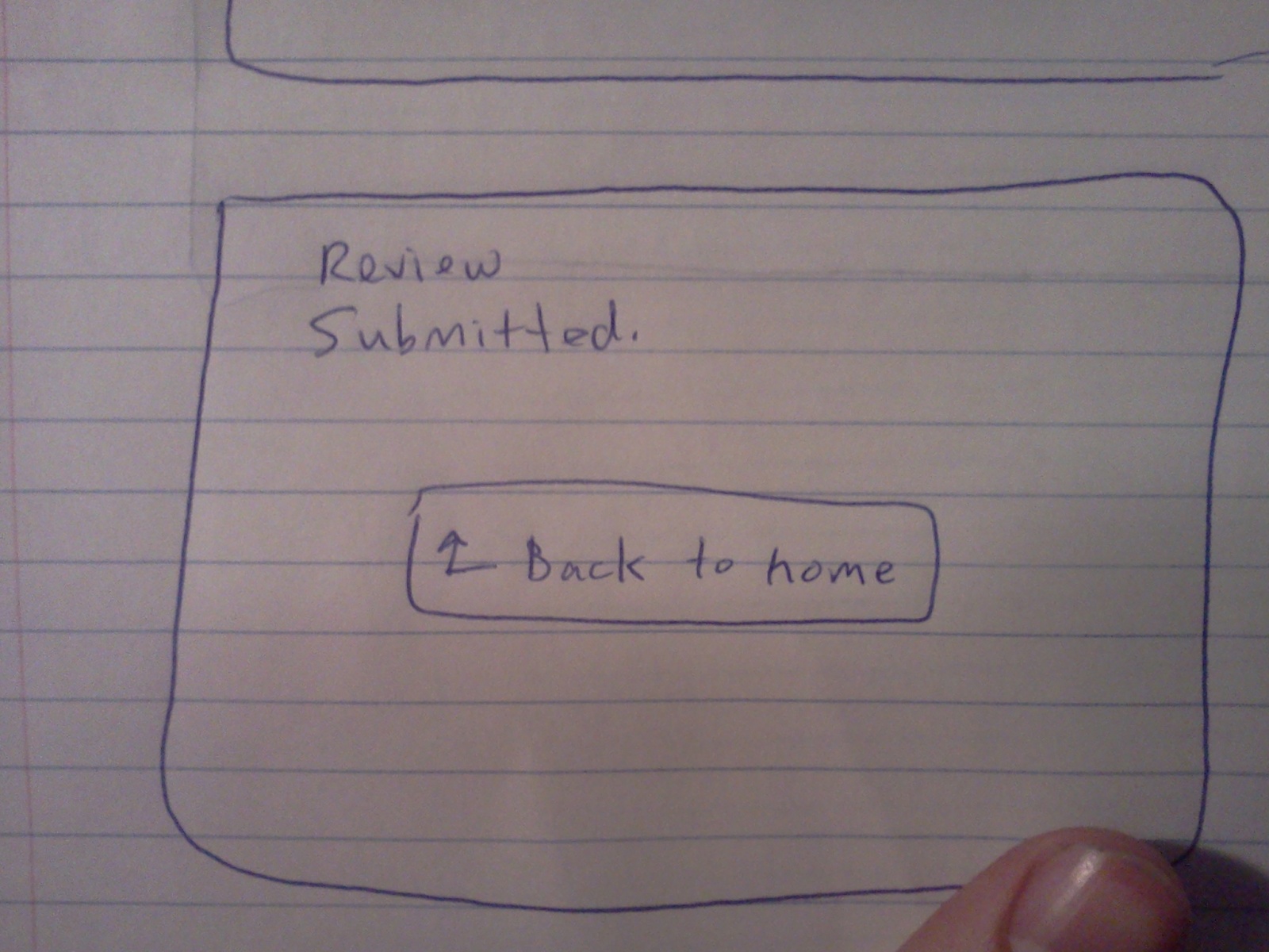
The success menu.

A display appears to notify the user that their document is successfully printing.


The user has various ways of getting from the main page to the “Printing” page depending on how they interact with the intermediate menus.

A overview of the application

To-Do List App

The main feature of the To-Do list app is that helps students quickly navigate through the tasks that they typically complete between classes. When students add a task to the to-do list, in addition to the title, they must also give the name of the application needed to complete that task. For example, sending an email might use Mail or Thunderbird, while editing a document might use Microsoft Word. After selecting an application, the user must select the file or url of the resource they wish to modify. For example, if the task involved editing a document in Microsoft Word, he would enter the file path of the document. After creating a to-do list, the user presses “Start!” When the user presses start, the program traverses their todo list, automatically opening the necesarry resources. The todo list application maintains a small dialogue box in the corner of the user’s screen so that the user can move between tasks and can navigate back to the main page.

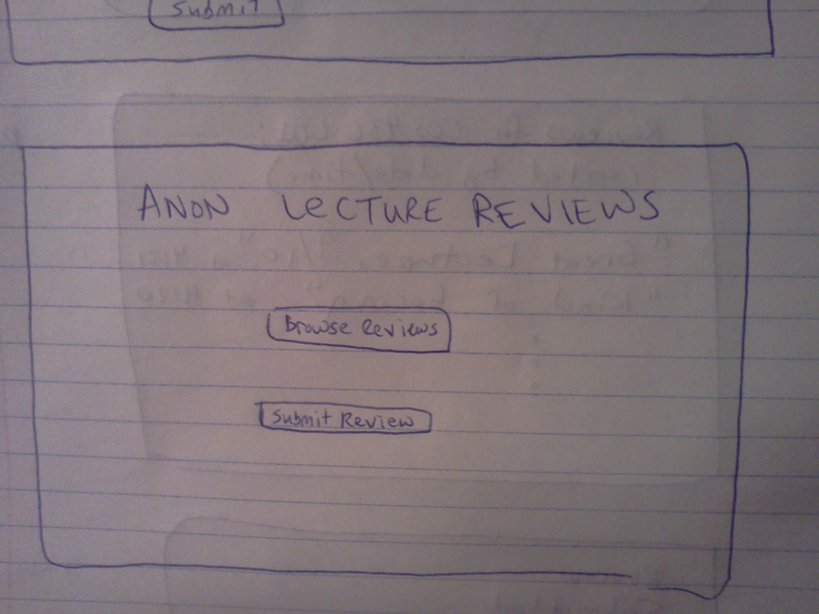
The main page of the todo list app consists of a list of the users tasks, with the options to add an entry or to start their to do list.

The main page

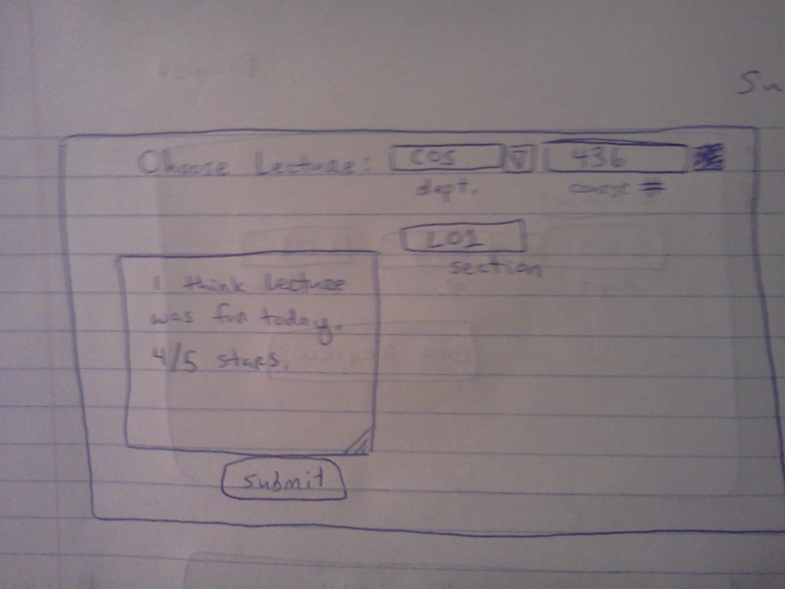
When users click the “New Entry” button, the are prompted with a form with which they fill in information about their task. The information requested is the title of the task, the application need to complete the task, and the file or url where the task can be accessed. Ideally the file/url entry section would be updated once the application section is filled in so the to-do list knows which resource it needs.

A form to create a new task

To choose an application, the user selects from a drop down menu. To choose a file/url, the user either enters a url directly or can browse their file system to find the correct address.

A drop down menu appears to allow the user to select an application.
A file system browser allows the user to select a file.

From the main menu, the user also has the option to edit an entry in the to do list. Likewise, certain local applications, like Mail, may not need a file/url inorder to start up.

This menu allows a user to edit an entry in the task list

Tasks Read: “Email Joe,” “Check Bank Account,” “Fill Out Survey,” “Proof Read HW”

When the user presses start, the correct application programs start. For example, the first drawing shows a new email window so the user can email Joe. The to-do list displays a small dialog box in the corner of the screen to remind the user that it is running and to allow the user to move to the next item in the list. Pressing the “next” button, for example, could automatically open Microsoft Word with the user’s homework so that they can edit it.

A view of the todo list application while the user is completing tasks.

5. Photos, descriptions, and detailed notes from user testing:

Test Structure: The structure of the test was that I presented the paper prototype to users telling them to interact with the paper as if it were a computer application. I tried to let them interact with it on their own at first, but offered help if help was needed. I started by giving them a card with a blank todo list queue. They then had to add tasks to the todo list and click “Start!” once tasks were added. I say they “had” to do this because this is really the only useful way to use the application.

1) Test 1

-Sarah clicking the “Application” button in the “New Entry” form.
-One common mistake was clicking “Start!” When the todo list was empty

For my first test, I demoed the application to Sarah. During her demo, the first thing she did was hit the “Start!” button. I then told her the the “Start!” button does nothing because there is nothing in her todo list queue. She then clicked the “New Entry” button. This brought up the new entry form. She then entered the title of the task, the application, and file path. After entering tasks, she was directed back to the todo list queue. She then clicked the “Start!” button. She was slightly confused when the email interface popped up, but she completed her first task, and clicked the “next” button. The second task then appeared and she clicked the “next” button. The simulation ended.

2) Test 2

-Mike attempting to start the to do list by clicking an individual task

For my second test, I demoed the application to Mike. Like Sarah, the first thing he did was hit the “Start!” button. I also told him that the “Start!” button does nothing because there is nothing in his todo list queue. After questioning the purpose of the application, he then clicked the “New Entry” button. This brought up the new entry form. He entered the title of the task and then entered the application. He asked about the “File/Url” field, for he was a bit confused as to why he would need to enter this information for a todo list.  He then entered the file path. After adding tasks to his queue, he was directed to the todo list queue. Instead of clicking “Start!” though, he clicked on an individual task, in an attempt to complete that task. Clicking an individual task, however,  does nothing. He then clicked the “Start!” button. His first task appeared, he completed the task, and he clicked the “next” button. The second task then appeared, he completed the task and he clicked the “next” button. The simulation ended.

At the end of the demo when I spoke with Mike he said he didn’t think he would personally use this application. He said he would “just do the task” rather than take time to add it to a list of small things to do later.

Test 3)

Kyle looking over the main page of the todo list app

For my third test, I demoed the application to Kyle. Like Mike and Sarah, the first thing he did was hit the “Start!” button. I also told him that the “Start!” button does nothing because there is nothing in his todo list queue. He then clicked the “New Entry” button which brought up the new entry form. He entered the title of the task, the application, and file path/URL. Like Mike, he also asked why the File/URL is needed. After adding tasks to his queue, he was directed to the todo list queue. He then clicked the “Start!” button. Like Sarah, he wasn’t exactly sure why the email interface appeared but after some direction, he completed the task. He, however, but did not immediately find the “next” button. I pointed out the “next” button and he clicked it. The second task then appeared, he completed the task and he clicked the “next” button. The simulation ended.

6. List of insights from testing.

  1. All 3 test users clicked the “Start!” button while the queue was empty
    1. My first thought to solve this problem is to eliminate the “Start!” button from the main page when the todo list is empty. I think this could work, although it’s possible that the word “Start!” could be confusing even when there are items in the list.
    2. A second solution would be to change the word “Start!” to “Execute To Do List”, or “Do!” or something more descriptive and straightforward than “Start!”.
  2. Users questioned why a file or url was necessary for a todo list
    1. To solve this problem I think it would be helpful the user to have more background information on the application. The user is supposed to go into this kind of test blind, so it might be helpful to add a more descriptive welcome page to the application to introduce its basic concept.
  3. Users were surprised when the page changed from the todo list queue to email when they pressed “Start!”
    1. Once again, I think it would be helpful for users to have more background of the purpose of the application. One idea would be to change the page sequence and make a “loading screen” appear when the user presses “Start!” that says something like “Now starting your todo list…opening HW.doc with Microsoft Word…”
    2. I think changing the word “Start!” to something more descriptive would be helpful to with problem as well.
  4. Users had trouble finding the “next” button or needed me to point out the small todo list dialogue box in the corner.
    1. I think I could make the dialogue box more prominent so that users are aware of its presence and can use the “next” button to go to the next task.
    2. After the user clicks “Start!” and the proposed loading screen appears, I could have the message in the loading screen make note of the fact that a dialogue box will appear.
  5. One user clicked on an individual task in order to attempt to complete that task
    1. I think that I should make clicking individual tasks have some functionality. I think it makes sense that users should be able to sort tasks in the todo list by dragging them.
  6. Users questioned the purpose of the application
    1. Though the application was somewhat confusing on it’s own, when I described the application to users myself, they saw its use. I think I should find a way to work my description of the app into the interface itself. Maybe some progress bar or instruction set like “Add Entries -> Sort Entries -> Execute List!” on the main page would be helpful.
    2. I think the fact that the application was made of paper was unusual for my users. I think this may have made the app seem more strange.

In all, I think my app was successful in that users were able to navigate through it reasonably quickly and understood its purpose with a little help from me. The biggest problem though is that it leaves much for explanation. I think the main goal of the revisions above are mainly to make the application and interface explain itself more clearly through better wording, button options, and page sequences.

Assignment 2 (Michael Newman)

Name: Michael Newman (menewman@)

My observations:
Every Tuesday and Thursday, I have two consecutive classes in the same room (Aaron Burr 219), as well as two consecutive classes in the CS Building (105 and 104). Consequently, I was able to observe the behavior of students/faculty between classes for the full 10-minute changing period twice a day on Tues/Thurs for the last couple of weeks. I observed that my peers tend to spend the extra time going to the water fountain and/or the bathroom, pulling out preparatory materials for class (laptops, books, printed notes, notebooks), conversing with the professor (particularly after class, not before), conversing with each other (occasionally, but not always, about course-related material), and using their phones – to text, call, browse the web, play games, or listen to music. Depending on the time of day (and the location), students may acquire/consume food or beverages – for example, I’ve seen COS students run to the tea room for coffee or to the vending machines for soda/snacks. This seems more likely to happen in the afternoon than in the morning. Professors, on the other hand, are less likely to spend the time socializing; in general they seem to roll into class with just enough time to set up their slides/projector and begin the lecture. After lecture, they tend to converse with students, pack up, and disappear. In general, both students and professors seem to spend the in-between time performing some combination of social interaction (in-person or via phone), personal refreshment (e.g., eating, going to the bathroom), and/or preparation for the class – not including, of course, travel time between classes.

Brainstormed ideas:
1. Online/mobile app that lets students anonymously rate the lecture they just attended, and/or provide direct feedback to the professor.
2. Mobile app that lets you know if your friends are planning to skip class; you can either coordinate so that someone always goes, or skip class if they are also skipping.
3. Mobile app that finds location on campus using GPS/Wifi, directs to nearest bathroom/food/water.
4. Mobile app that calculates distance to next class and estimates how long it will take you to get there.
5. Web app that lets you anonymously chat with those in the same lecture as you; you can ask questions and get immediate feedback without feeling embarrassed or put on the spot.
6. Kinect-based “stretching station” where students who have been sitting down too long can work out their stiffness with the help of a stretching game/program.
7. Mobile/web app where professor can upload class notes and student can send them all to All_Clusters with a single click (also provides printer location information).
8. Web app where students can anonymously gossip about their classmates (sorted by class, lecture time for convenience) and read gossip about themselvers.
9. Mobile app that uses current location data and time/location of next class to determine if it’s feasible to go get coffee before the next class starts.
10. Mobile app that plays soothing instrumental music and shows calming visuals (e.g., ocean waves) to help students relax between classes.
11. Web/mobile app that lets professors know what equipment/connections they should be prepared for in a given lecture hall (e.g., VGA adaptor only, HDMI connection, etc.)
12. Web/mobile app that provides a calendar of assignment due dates and exams; students can check to see if they have something to turn in for their next class.
13. Web/mobile app where professors can upload short outlines/background info on the upcoming lecture, which students can check on their phones before class.
14. “Assassins” mobile app: participating students can receive the names of targets to “assassinate” (with water pistols) between classes, and the last student still “alive” receives a prize.
15. Web/mobile app where student can log how much time they’ve spent outside each day; app reminds them to go outside between classes so they can get some sunlight and vitamin D.

The ideas I chose to prototype:
Online/mobile app that lets students anonymously rate the lecture they just attended, and/or provide direct feedback to the professor.
I like this one because it lets the student ask questions or suggest improvements while the lecture is still fresh in his/her mind; the professor can then respond to issues s/he otherwise might not even have known about.

Mobile app that finds location on campus using GPS/Wifi, directs to nearest bathroom/food/water.
This is useful because students often use their short breaks relieving/refreshing themselves, but they have only 10 minutes to walk to their next class, acquire/consume a snack, and/or use the bathroom – and in a strange building, students might have a hard time finding vending machines or a bathroom.

Prototype 1: Anonymous Lecture Feedback

Home page. User can either browse others' reviews or submit a review.

Home page. User can either browse others’ reviews or submit a review.

The user can use this form to submit a review for a lecture.

The user can use this form to submit a review for a lecture.

User gets this screen after submitting a review. It links back to the home page.

User gets this screen after submitting a review. It links back to the home page.

The user searches for reviews by department, course number, and section.

The user searches for reviews by department, course number, and section.

After the user chooses a course and section, s/he can browse the reviews from most to least recent.

After the user chooses a course and section, s/he can browse the reviews from most to least recent.

Prototype 2: Refreshment Buddy

Home screen. User must first acquire location, then look for food/water/bathrooms.

Home screen. User must first acquire location, then look for food/water/bathrooms.

If user tries to find food/water/bathroom without first acquiring location. they get this message.

If user tries to find food/water/bathroom without first acquiring location. they get this message.

The user gets this screen once the app has found their location.

The user gets this screen once the app has found their location.

The app shows nearby places to get food when the user clicks "find food."

The app shows nearby places to get food when the user clicks “find food.”

The app shows nearby water fountains when the user clicks "find water."

The app shows nearby water fountains when the user clicks “find water.”

The app shows nearby bathrooms when the user clicks "find bathrooms."

The app shows nearby bathrooms when the user clicks “find bathrooms.”

Map view shows the user's location and the location of nearby food/water/bathrooms.

Map view shows the user’s location and the location of nearby food/water/bathrooms.

User Testing:
I chose to test my second prototype, “Refreshment Buddy,” with the help of three fellow students: Katie, Charles, and Osei. During this process, they interacted with my paper “screens” as if they were using a mobile device; when they clicked a button, I would give them the appropriate piece of paper to account for that action. They provided feedback, both directly and indirectly (through observation); the insights thus derived are listed in the section below.

Katie and Charles both clicked through pretty much every screen of the prototype (Acquire Location -> Find Food -> See Map -> Back -> Back -> Find Water -> See Map -> Back -> Back -> Find Bathrooms _> See Map -> Back -> Back). Osei, on the other hand, went through the process of finding food but stopped there, without looking for water/bathrooms. I provided the next screen for them after each “click” and let them know when they were trying to click something that wasn’t clickable, but otherwise I provided no prompting or instructions. All of them seemed confused by the purpose of the “Acquire Location” button, and Charles and Osei expressed an interest in having additional information about the food locations.

Katie clicks "acquire location."

Katie clicks “acquire location.”

Osei attempts to find food without acquiring his location first.

Osei attempts to find food without acquiring his location first.

When Charles clicks "see on campus map," I switch to the map screen.

When Charles clicks “see on campus map,” I switch to the map screen.

My hastily scrawled notes from user testing.

My hastily scrawled notes from user testing.

Insights from testing:
Katie
-It’s not immediately obvious what the app means by “acquire location.” What location? Should be more specific.
-It would be preferable to show one’s location on the map after acquiring it, and then just have nearby food/water/bathroom icons pop up on the map.
-The prototype doesn’t provide a way to change or re-acquire one’s location; having a constantly updated map display would solve that problem.

Charles
-It might be better to have more specific food locations, or to provide extra information about food (e.g., show only nearby free food).
-Liked the water fountain-finding functionality.
-Like Katie, wasn’t immediately sure what the location in “acquire location” meant. Should clarify the meaning.

Osei
-Wasn’t sure which elements of the app were clickable (e.g., tried to click on “Frist Gallery” under “Find Food” but could not).
-Would like extra details, such as information about the food available (menus? vending machine items?) at each location.
-Since I force him to click “Acquire Location” first anyway, I might as well just auto-acquire the location, or not show the links for finding food/water/bathrooms until after location has been acquired.

Nightlight/Wake-up-Alarm Combo, by the Elite Four (Lab 1)

Group Name: The Elite Four (# 24)

Members:
Clay Whetung (cwhetung@)
Jae Young Lee (jyltwo@)
Jeff Snyder (jasnyder@)
Michael Newman (menewman@)

What we built:
We chose to build a nightlight combined with a wake-up alarm. Our nightlight features not one, not two, not three, not four, not five, but SIX — yes, SIX! — LEDs that turn on when a photosensor detects a decreased amount of ambient light. Not only that, but we also included a buzzer that plays a friendly tune whenever our system detects that ambient light levels have increased again. The purpose of this system is twofold: First, by providing light when its surroundings are dark, it reassures and comforts those who are afraid of the dark. Second, it audibly announces the return of light to those who might have closed their eyes or otherwise lost sensory input (e.g., the sleeping or suddenly blind). Our system is a smashing success, as it correctly lights up in the dark and plays a tune, as specified. We particularly liked the reassuring charm of the system’s adorable lights and catchy jingle. A possible improvement would be implementing a continuous alarm that the user can turn off (for example, by turning a potentiometer) — more like a typical alarm clock. We could even include a snooze button.

Design sketches:

IMAG0130

Arduino Orchestra Instrument: Pitch is controlled with soft pot, and volume is controlled with FSR.

IMAG0132

Etch-a-Sketch: Potentiometers control the x and y coordinates of the “pen,” and a drawing is rendered onscreen using Processing.

IMAG0135

Nightlight/Alarm Clock: LEDs turn on when the light dims, and buzzer goes off when light is restored.

Storyboard:
IMAG0133

IMAG0134

Photos of our system:

The entire system

The entire system

Arduino's connections

Arduino’s connections

Big breadboard connections

Big breadboard connections

Little breadboard

Little breadboard

LEDs during the day

LEDs during the day

LEDs when ambient light levels decrease

LEDs when ambient light levels decrease

Video of our system in action:

Ingredients:
– 6 LEDS (3 yel­low, 3 red)
– 1 speaker
– 1 photoresis­tor
– 1 Arduino
– jumper wires
– 2 bread­boards
– 6 330-ohm resis­tors
– 1 10k-ohm resis­tor
– 1 lap­top with usb cable

Recipe:

Circuit diagram

Circuit diagram

1. Set up the LEDs in a line on a bread­board next to the photoresistor. Place the speaker across the cen­ter divider of the other bread­board. You may find it help­ful to con­nect ground and +5V to the power rails of the bread­board for the fol­low­ing steps.

2. Make the fol­low­ing con­nec­tions:
– Con­nect the anodes of the 6 leds to pins 0-5 of the arduino.
– Con­nect the cath­ode of each LED to ground via a 330 ohm resis­tor.
– Con­nect one pin of the speaker to pin 8 and the other to ground via a 330 ohm resis­tor.
– Con­nect one side of the photoresistor to a +5V pin.
– Con­nect the other side both to A0 and to ground via a 10 kilo-ohm resistor.

3. Check the val­ues out­put by the photoresistor using the ser­ial mon­i­tor and the Serial.println() func­tion. In the code, change the PHOTO_MAX and PHOTO_MIN val­ues as appropriate.

4. Enjoy the comfort and security of living with the sweet alarm nightlight.

Source Code:

/* 
  Authors: jasnyder, cwhetung, menewman, jyltwo
  Date: 2/25/2013
  COS 436 Lab L1: The Nightlight Alarm

  The nightlight alarm: lights turn on when it's dark, and when it
  gets bright again, the lights turn off and an alarm goes off to 
  wake you up!
*/

#include "pitches.h"

const int FALSE = 0;
const int TRUE = 1;

//  Input / Output Constants
const int PHOTO_MIN = 100;  // set me as appropriate!
const int PHOTO_MAX = 1023;  // set me as appropriate!
const int DARKNESS = 500;  // set me as appropriate!
const int LIGHT = 700;  // set me as appropriate!

//  Musical Constants
const int NOTE_DELAY = 300; // (ms)
const int NOTE_DUR = 250;

//  Pin Connection Constants
const int photo = A0;
const int red1 = 5;
const int red2 = 3;
const int red3 = 1;
const int yellow1 = 4;
const int yellow2 = 2;
const int yellow3 = 0;
const int speaker = 8;

//  Variables
boolean islight = false;
int photovalue = 0;  //  value returned by photo sensor

//  Set internal pull-ups for output on LED pins
void setup()
{
  pinMode(red1, OUTPUT);
  pinMode(red2, OUTPUT);
  pinMode(red3, OUTPUT);
  pinMode(yellow1, OUTPUT);
  pinMode(yellow2, OUTPUT);
  pinMode(yellow3, OUTPUT);
}

void loop() {
  //  Grab the light value
  photovalue = analogRead(photo);

  // If it has recently become dark, turn on nightlight
  if (photovalue < DARKNESS && islight) {     
    digitalWrite(0, HIGH);     
    digitalWrite(1, HIGH);     
    digitalWrite(2, HIGH);     
    digitalWrite(3, HIGH);     
    digitalWrite(4, HIGH);     
    digitalWrite(5, HIGH);     
    islight = false;   
  }      
  // If it has recently become light, turn off nightlight and play alarm   
  else if (photovalue > LIGHT && !islight) {
    digitalWrite(0, LOW);
    digitalWrite(1, LOW);
    digitalWrite(2, LOW);
    digitalWrite(3, LOW);
    digitalWrite(4, LOW);
    digitalWrite(5, LOW);
    playAMerryWakingUpSong();
    islight = true;
  }
}

//  Play a classic little ditty!
void playAMerryWakingUpSong() {
  tone(speaker, NOTE_C5, NOTE_DUR);
  delay(NOTE_DELAY);
  tone(speaker, NOTE_C5, NOTE_DUR);
  delay(NOTE_DELAY);
  tone(speaker, NOTE_AS4, NOTE_DUR);
  delay(NOTE_DELAY);
  tone(speaker, NOTE_C5, NOTE_DUR*.75);
  delay(NOTE_DELAY*2);
  tone(speaker, NOTE_G4, NOTE_DUR*1.5);
  delay(NOTE_DELAY*2);
  tone(speaker, NOTE_G4, NOTE_DUR);
  delay(NOTE_DELAY); 
  tone(speaker, NOTE_C5, NOTE_DUR);
  delay(NOTE_DELAY); 
  tone(speaker, NOTE_F5, NOTE_DUR);
  delay(NOTE_DELAY); 
  tone(speaker, NOTE_E5, NOTE_DUR);
  delay(NOTE_DELAY); 
  tone(speaker, NOTE_C5, NOTE_DUR);
  delay(NOTE_DELAY); 
}

L1: Electronic Anti-Intoxication (or Overflow Detecting) Cup

Group 15: Prakhar Agarwal (pagarwal@), Colleen Carroll (cecarrol@), Gabriel Chen (gcthree@)

Description:
We chose to build a pressure sensitive cup because it was the most widely useful of all of our ideas, and we could imagine using it in everyday life for a number of different applications. The cup uses a force sensor to detect the amount of liquid in the cup and colored lights to indicate to the user how much they have filled/emptied the cup. The idea was originally inspired as an easy way to track your drinking on a night out. The best part of our design is that it requires almost no new interactions for the users to learn. You can fill or drink from the cup like you would with any other cup and the color scheme of the lights follows standard green/yellow/red signaling for go/slow/stop. In our video, we show the application of this to building an light-signaling overflow detector and our storyboard shows another application of this sort of technology to staying safe on a night out. As we have the cup now, it is easy to pour into, but hard to pour out of (because it is hooked up to the Arduino), which complicates certain use cases. With more time, we would make it more mobile, and we would also like to create a way for it to keep track of when the cup is filled/emptied multiple times.

Photos of Sketches:

Air Bass Sketch

Air Bass Sketch

Fat Belt Sketch

Fat Belt Sketch

Overflow Cup Sketch

Overflow Cup Sketch

Storyboard:

sb1sb2sb3sb4

Live in Action:

http://www.youtube.com/watch?v=-wj1bbwfeVo

Photo of the full setup

Photo of the full setup

Photo showing the outer cup with sensor and LEDs

Photo showing the outer cup with sensor and LEDs


Photo showing the bottom of the inner cup with a piece of styrofoam used apply pressure directly to the pressure sensor

Photo showing the bottom of the inner cup with a piece of styrofoam used apply pressure directly to the pressure sensor

Materials:

  • 2 plastic cups
  • FSR
  • 3 LEDs (green, yellow, red)
  • small piece of Styrofoam or cardboard
  • alligator clips
  • electrical tape
  • Knife
  • Arduino
  • USB cable
  • Breadboard

Instructions:

  1. Start by cutting one cup to about half of its original height. This will make it easier to attach the electronic components to the bottom.
  2. Pierce a slit in the bottom of the cup. Put the FSR through the slit so that the round sensor is centered inside the cup and the long end is sticking outside.
  3. Next, pierce three sets of 2 small holes in the bottom of the cup. You stick one LED in each of these sets so that the light is on the inside of the cup and the wires are sticking out.
  4. Fit the uncut cup inside the cut one. Notice the size of the gap between the bottom of the inside cup and the bottom of the outside cup.
  5. Cut a piece of Styrofoam or cardboard to the shape and size of the head of the FSR and then tape it over the FSR. This will serve as padding between the top cup and bottom cup so that the top cup will put pressure directly on the FSR, through the padding, as it is filled with water. (Note: Ensure that the padding is taller than the LEDs.)
  6. Set up the circuit as shown in the schematic so that each of the lights is connected independently to a digital input on the Arduino.
  7. Test the FSR. Note the reading when the cup is empty, half way full, full, and about to overflow.
  8. Write your program so that: If you are sensing an overflowing cup, the yellow lights up at half way, green at full, and red at overflowing. If you are sensing a draining cup, green lights up at full, yellow at halfway, and red at empty.

Code:

const int ledYellow = 2;
const int ledRed = 4;
const int ledGreen = 7;
int fsrPin = 0; // the FSR and 10K pulldown are connected to a0
int fsrReading; // the analog reading from the FSR resistor divider

void setup(void) {

// We'll send debugging information via the Serial monitor
Serial.begin(9600);

pinMode(ledRed, OUTPUT);
pinMode(ledYellow, OUTPUT);
pinMode(ledGreen, OUTPUT);

}

void loop(void) {

fsrReading = analogRead(fsrPin);

if (fsrReading < 500) {
digitalWrite(ledRed, LOW);
digitalWrite(ledGreen, LOW);
digitalWrite(ledYellow, LOW);
}

if (fsrReading > 500 && fsrReading <= 600) {
digitalWrite(ledRed, LOW);
digitalWrite(ledGreen, LOW);
digitalWrite(ledYellow, HIGH);
}

if (fsrReading > 600 && fsrReading <= 680) {
digitalWrite(ledRed, LOW);
digitalWrite(ledGreen, HIGH);
digitalWrite(ledYellow, LOW);
}

if (fsrReading > 680) {
digitalWrite(ledRed, HIGH);
digitalWrite(ledGreen, LOW);
digitalWrite(ledYellow, LOW);
}

Serial.print("Analog reading = ");
Serial.println(fsrReading); // the raw analog reading
delay(100);
}

Ambient Etch-a-Sketch

Connie Wan (cwan), Angela Dai (adai), Kiran Vodrahalli (knv), Edward Zhang (edwardz)

Group 13 (aka CAKE)

We built a pseudo Etch-A-Sketch emulator that modifies its appearance based on the user’s environment – the temperature and light conditions. Instead of only drawing horizontal and vertical lines, we can draw curved lines by changing the slope of the current line to be drawn. We use two potentiometers to serve as the knobs of this “Curve-A-Sketch” and use Processing to display the user’s drawing. The ambient light level controls the color of the drawing, while the temperature controls the width of the stroke. This project was a lot of fun to play with because of the nostalgia of playing with a childhood toy, enhanced with the novel control of changing its color and stroke width – for example, we could change colors simply by touching the temperature sensor, and width by moving our head over the photoresistor. We also wanted to blow on the temperature sensor to change color, but it didn’t quite work out because of some bugs with a clear button. The clear button only worked sometimes, because the circuit was a bit buggy– quick changes in resistance messed up the data we sent from the Arduino to processing.

Sketches

Ambient Etch-A-Sketch: Remember the Etch-a-Sketch? This lets you do everything the Etch-a-Sketch did, and more! The features of your cursor , such as color and pen width, change based on your ambient environment conditions (temperature and light).


The upper half of this image shows an LED light array that lights up in concert with the location of your finger. With an added control for color, you can create a mini light show using just your hands.
The lower half shows our Smart Nightlight. As its basic function, the tricolor LED will be brighter if the room is darker (we put a screen between the LED and the photoresistor to eliminate feedback). The user can change the color and the overall brightness of the nightlight.


Storyboard

Ambient Etch-A-Sketch Storyboard

Final System


This video demonstrates the features of our Ambient Etch-a-Sketch. It shows the user controlling the color and pen width with the photoresistor and thermistor, respectively.

List of parts

  • 2x Potentiometer (rotary)
  • 1x Arduino Uno
  • 1x Push Button
  • 1x Photoresistor
  • 1x Thermistor
  • 3x 10KΩ Resistor
  • 1x Breadboard
  • Wires
  • Computer

Instructions

  1. Plug the two potentiometers into opposite sides of the breadboard. Fix an orientation – the one on the left controls the horizontal coordinate, and the one on the right controls the vertical coordinate. Attach the middle pin of the right potentiometer to A0 and the middle pin of the left potentiometer to A1. Attach the side pins of both potentiometers to 5V and ground.
  2. Connect one side of the thermistor to 5V, and the other side to A2 and ground through a 10KΩ pull-down resistor.
  3. Connect one side of the photoresistor to 5V, and the other side to A2 and ground through a 10KΩ pull-down resistor.
  4. Connect one side of the push button through a 10KΩ resistor to 5V and the other side to D2 and ground.
  5. Run the Arduino code, and then start the Processing application
  6. Draw! The extreme settings of the knobs correspond to the sides of the Processing window. You can adjust the color by shadowing the photoresistor (e.g. leaning over so your head blocks some light), and change the stroke width by changing the temperature (the easiest way is by pressing the thermistor between your fingers).

Source Code

Arduino Code

/*
 Ambient Etch-a-Sketch!
 Lab 1
 COS 436: Human-Computer Interfaces
 February 20, 2013
 
 */

//variables 
int y; //y coordinate of etch-a-sketch
int x; //x coordinate of etch-a-sketch
int temperature; //temperature of the room 
int light; //light ambience of the room 
int clearButton; //clear Button 

//pins
int pinY = 0; 
int pinX = 1; 
int pinTemperature = A2; 
int pinLight = 3; 
int pinClearButton = 7;

void setup()
{
  // initialize the serial communication:
  Serial.begin(9600);
  
  // initialize the clear button as an input 
  pinMode(pinClearButton, INPUT);
  
}

void loop() {
  // read data on every loop 
  x = analogRead(pinX);
  y = analogRead(pinY);
  light = analogRead(pinLight);
  temperature = analogRead(pinTemperature);
  clearButton = digitalRead(pinClearButton);
  
  //test it works
  //Serial.println("Scaled x: \n");
  if((x < 1024) && (y < 1024) && (light < 1024) && (temperature < 1024) && (clearButton <= 1)) {
    Serial.println(x); 
    Serial.println(y);  
    Serial.println(light); 
    Serial.println(temperature);
    Serial.println(clearButton);
  }
  delay(100);
}

Processing Code

//Lab 1: Resistance 
//Connie Wan, Angela Dai, Kiran Vodrahalli, Edward Zhang 
//Feb 27, 2013

import processing.serial.*; 

Serial myPort;
float dx; //change from controls
float dy; //change from controls
float old_dx; //check prev
float old_dy; //check prev
float x; //curent position 
float y; //current position
float light;  //current lighting
float temperature; //current temperature 
int clearButton; //clearButton 
String input; //get data from Arduino 

static final int X_WIDTH = 400;
static final int Y_HEIGHT = 400;
static final int UNIT_DRAW = 20; 

void setup() {
  //init
  myPort = new Serial(this, Serial.list()[4], 9600);
  println(Serial.list());
  x = 200;
  y = 200;
  size(X_WIDTH, Y_HEIGHT);
  colorMode(HSB, 255, 255, 255);
  background(0, 0, 255);
  stroke(0); 
  myPort.clear();
  if(myPort.available() > 0) {
    input = myPort.readStringUntil('\n');
    if(input != null){
      String xval = trim(input);
      old_dx = Integer.parseInt(xval);
      println(dx);
    }
    
    input = myPort.readStringUntil('\n');
    if(input != null) {
      String yval = trim(input);
      old_dy = Integer.parseInt(yval);
      println(dy);
    }
   
    input = myPort.readStringUntil('\n');
    if(input != null) {
      String lval = trim(input);
      light = Integer.parseInt(lval);
      println(light);
    }
  
    input = myPort.readStringUntil('\n');
    if(input != null) {
      String tval = trim(input);
      temperature = Integer.parseInt(tval);
      println(temperature);
    }
    input = myPort.readStringUntil('\n');
    if(input != null) {
      String cval = trim(input);
      clearButton = Integer.parseInt(cval);
      println(clearButton);
    }
  }
  myPort.clear();
}

void draw() {
  
 while(myPort.available() > 0) {
    input = myPort.readStringUntil('\n');
    if(input != null){
      String xval = trim(input);
      dx = Integer.parseInt(xval);
      //println(dx);
    }
    else {
      return;
    }
    input = myPort.readStringUntil('\n');
    if(input != null) {
      String yval = trim(input);
      dy = Integer.parseInt(yval);
      //println(dy);
    }
    else {
      return;
    }
    input = myPort.readStringUntil('\n');
    if(input != null) {
      String lval = trim(input);
      light = Integer.parseInt(lval);
      //println(light);
    }
    else {
      return;
    }
    input = myPort.readStringUntil('\n');
    if(input != null) {
      String tval = trim(input);
      temperature = Integer.parseInt(tval);
      //println(temperature);
    }
    else {
      return;
    }
    input = myPort.readStringUntil('\n');
    if(input != null) {
      String cval = trim(input);
      clearButton = Integer.parseInt(cval);
      println(clearButton);
    }
    else {
      return;
    }
    myPort.clear();

    if(clearButton == 1) {
      background(0, 0, 255);
    }
    
    //scaling
    
    
    dx = UNIT_DRAW*((dx/1023.0) -0.5);
    dy = UNIT_DRAW*((dy/1023.0) - 0.5);
    
    light = light/1023.0;
    temperature = (temperature - 500) *(255.0/100.0);
    if(temperature  255) {
        temperature = 255;
    }
    
    println(temperature);
    //change color
    stroke(temperature, 255, 255);
    //change thickness
    strokeWeight(10*light);
      if(x >= X_WIDTH) {
          x = X_WIDTH;
      }
      if(y >= Y_HEIGHT) {
          y = Y_HEIGHT;
      }
      print("x: " + x + "\n");
      print("y: " + y + "\n");
      
      if(((dx  old_dx -.01))){
        dx = old_dx;
      }
      if(((dy  old_dy -.01))){
        dy = old_dy;
      }
      
      if((dx != old_dx) || (dy != old_dy)){
        line(x, y, x + dx, y + dy);
        x = x + dx;
        y = y + dy;
     
        old_dx = dx;
        old_dy = dy;
      } 
  } 
}

L1: Expressive Drum Pad

Krithin Sitaram (krithin@)
Amy Zhou (amyzhou@)
Daniel Chyan (dchyan@)
Jonathan Neilan (jneilan@)
Thomas Truongchau (ttruongc@)

Group 11

Expressive Drum Pad

We built a drum pad that can play a range of pitches controlled by a softpot (touch sensitive slide), along with a range of amplitudes controlled by a FSR. The harder a performer strikes the FSR, the louder the buzzer sounds. Sliding towards the right will cause an increase in pitch, while sliding towards the left will cause a decrease in pitch. Combining the two controls, a performer can play a variety of virtuosic pieces that require a single voice. We decided to build the Expressive Drum Pad because we all appreciate music creation and wanted to contribute to the creative musical process. The Expressive Drum Pad turned out nicely as it allows the performer to control pitch and amplitude rather effectively through an intuitive, yet unpolished interface. Future improvements would include having an enclosure to hold down the sensors.

http://www.youtube.com/watch?v=VD8VC3npgwg

Parts Used
– 1 Arduino
– 1 FSR
– 1 softpot (touch-sensitive slide)
– Buzzer (replaced by computer speakers for additional volume)
[Reid approved this substitution.]

Connect the softpot to 5V, Ground, and an Arduino analog input pin. Connect the buzzer (computer speakers) in series with the FSR as part of the circuit from an Arduino digital output pin to ground. Angle the breadboard such that the softpot and FSR lie flat on a table.

Source Code:

int OUTPUTPIN = 3;
int FSRPIN = 5;
int SOFTPOTPIN = 0;
int MINSOFTPOT = 0;
int MAXSOFTPOT = 1024;
int MINPITCH = 120;
int MAXPITCH = 1500;

void setup() {
pinMode(OUTPUTPIN, OUTPUT);
Serial.begin(9600);

}

void loop() {
int frequency = map(analogRead(SOFTPOTPIN), MINSOFTPOT, MAXSOFTPOT, MINPITCH, MAXPITCH);
tone(OUTPUTPIN, frequency);
delay(2);
Serial.println(analogRead(FSRPIN));
}

Sensor-Based Authentication

1) Names: Philip Oasis, Alice Fuller, Gene Merewether, and Rodrigo Menezes
2) Group Number: 6
3) We built a sensor-based authentication system. The idea behind it is that you enter in a code the first time, and then on subsequent uses you have to enter in the same code. We had three sensors: two potentiometers which had to be turned the correct degree and one slide sensor which had to have your finger placed in the correct position. The end result was really great. The correct position, given a small amount of error could be found again, but a knowledge of the initial code was still needed. When you got the code correct a green light went off, and when you got it wrong a buzzer went off. I enjoyed the fact that you had to have your finger in the correct position on the sensor while you pushed the button, the multiple tasks reminds me of cool authentication systems that you see in movies. It might have been nice to have things in a prettier display; we could have obscured the wires better, had the sensors further apart to improve ease of movement, had written instructions. This would have also been much better if there was an actual lock to unlock.

4)

This is a simple reaction game in which the buzzer sounds, the user hits the button as quickly as possible, and the LED then lights up to give them feedback on how quickly they reacted.


This is a memory game in which the user hits buttons to recreate the order the LED’s flashed, and the sequence gets one light longer for each round the user gets correct.


This is a racing reaction game in which the LED flashes red, yellow, and green and then the user tries to hit the button as soon as possible after a green.  The buzzer would go off in the event of a false start, and the LED would light up with a color to indicate the reaction time.

5) Storyboard:

6) Demo Video: Lab 1

7) Parts List

  • 2 potentiometers
  • 1 slide sensor
  • 1 button
  • 1 buzzer
  • 1 green LED
  • 2 bread boards
  • 1 arduino
  • 2 330Ω resistor
  • 1 10kΩ resistor

8) Directions

Attach these all on one breadboard:
Attach one potentiometer to pin 0 on the arduino, the other to pin 1. Attach the button to pin 2, the buzzer to pin 3, and the led to pin 5. There should be a 330 ohm resistor attached with the led and the buzzer, and a 10k ohm to the button. The two potentiometers should be next to each other at the front, the button should be just behind them, and the buzzer and led are at the back of the breadboard. On the separate smaller breadboard place the slide sensor and connect it to pin 2.

9) Source Code

const int potentialPin1 = 0;
const int potentialPin2 = 1;
const int slidePin = 2;

const int buttonPin = 2;
// pull-down resistor; LOW is not pressed
const int buzzerPin = 3;
const int ledPin = 5;

const int tolerance = 64;
const int buzzerTone = 20;

int lock1 = -1;
int lock2 = -1;
int lock3 = -1;

void setup()
{
pinMode(buttonPin, INPUT);
pinMode(buzzerPin, OUTPUT);
pinMode(ledPin, OUTPUT);
Serial.begin(9600);

while (digitalRead(buttonPin) == LOW) // wait until button is pressed
{
delay(100);
}

// enter in lock code
lock1 = analogRead(potentialPin1);
lock2 = analogRead(potentialPin2);
lock3 = analogRead(slidePin);
digitalWrite(ledPin, HIGH);
Serial.print(“Potentiometer1 = “);
Serial.println(lock1);
Serial.print(“Potentiometer2 = “);
Serial.println(lock2);
Serial.print(“Slide sensor = “);
Serial.println(lock3);
}

void loop()
{
int buttonState = digitalRead(buttonPin);
int potentialState1 = analogRead(potentialPin1);
int potentialState2 = analogRead(potentialPin2);
int slideState = analogRead(slidePin);

Serial.print(“Potentiometer1 = “);
Serial.println(potentialState1);
Serial.print(“Potentiometer2 = “);
Serial.println(potentialState2);
Serial.print(“Slide sensor = “);
Serial.println(slideState);

if (buttonState == HIGH) // pressed
{
if ((potentialState1 < (lock1 + tolerance)) &&
(potentialState1 > (lock1 – tolerance)) &&
(potentialState2 < (lock2 + tolerance)) &&
(potentialState2 > (lock2 – tolerance)) &&
(slideState < (lock3 + tolerance)) &&
(slideState > (lock3 – tolerance)))
{
digitalWrite(ledPin, HIGH);
delay(1000);
}
else // not correct code
{
digitalWrite(ledPin, LOW);
analogWrite(buzzerPin, buzzerTone);
delay(1000);
}
}
digitalWrite(ledPin, LOW);
analogWrite(buzzerPin, 0);
}

Lab1

Group Members: Matthew Drabick, Adam Suczewski, Andrew Callahan, Peter Grabowski

High Level Description:

Access to inexpensive, portable medical equipment is a serious problem in many developing countries. There are currently solutions available, but many ignore the diagnosis of neurodegenerative disorders. We aim to provide a compact, easy to use package to aid in the diagnosis of such diseases using 3 basic tests.

First, our diagnostic suite includes a spirometer to measure lung capacity and expulsion rate. This is an important metric, for shortness of breath can be an indication of increased brain pressure, stroke, or tumors (Shortness of Breath).

Second, our diagnostic suite includes a measure of reaction time. Many patients with Parkinson’s disease have difficulty initiating movement, and as a result exhibit an increase in reaction time (Movement Disorders). This test can help diagnose some of those cases.

Third, our diagnostic suite includes a digital strength test. Difficulty with finger movements or strength can be an indicator of polyneuropathy (Physical Examination). Our strength test attempts to give a more honest evaluation of finger strength.

Physicians or volunteers can use our simple device to as a preliminary test for many neurological conditions. While the diagnosis is no means certain, it can be a useful tool to identify patients who are good candidates for further diagnostic testing. Below is an image of the system.


A look at the final product


Works Cited

Bozkurt, Biykem, and Douglas Mann. “Shortness of Breath.” Shortness of Breath. N.p., n.d. Web. 23 Feb. 2013.

“Movement Disorders.” American Association of Neurological Surgeons, n.d. Web. 23 Feb. 2013.

“Physical Examination: Diagnosis of Brain, Spinal Cord, and Nerve Disorders.” Physical Examination: Diagnosis of Brain, Spinal Cord, and Nerve Disorders: Merck Manual Home Edition. Merck, n.d. Web. 23 Feb. 2013.

Story Board:


High Level Design Process:

During the brainstorming stage we came up with a few ideas including:

-A system to control a lamp based on lighting in the room (turn the lamp off if the room is light, turn the lamp on if the room is dark)

-A system to detect different types of coins using an FSR.

-A flex sensor controlled etch a sketch that draws to a computer monitor.

We decided to go with the medical testing suite because it’s flexible, potentially useful, and uses a wide array of the resistive sensors in our arsenal.

Our initial design looked something like this:

The idea was to have the 3 tests stationed radially on a platform. We would then have the user select a test using the pot in the center of the 3 tests. After writing our code though and implementing the tests on breadboards, we soon encountered difficulty with this setup. The challenge was that without soldering, we could not connect wires to our circuit components. To overcome these design issues, we changed our design to something more similar to the sketches below using several breadboards. In this setup, we moved the pot off to the side, and gave each test its own independent “station.”


The tests are spread out as far as possible using 3 breadboards. The pot is used to select the test.

Another design sketch when were realized we needed to rearrange circuit components.

The reaction time test “station”

Though this implementation was not as smooth or intuitive as the one we imagined, we were satisfied with the implementation given the materials we were working with. It took a bit of tweaking and trying different layouts to get our system in order, but in the end the system was structurally stable, functional, and reasonably easy to understand.

In addition to the physical layout of the testting system, we also had to work out the design of the tests themselves. We had the most trouble getting the spirometer working. Sometimes, the spirometer would not register when a user started blowing, while other times, it would think the user had stopped blowing when the user had not. To overcome these problems we tried directing the user’s breath through tubes, changing the position and width of the spirometer fan, and playing with the delay right before the start of the test. In the end it took the right modification of each of these factors to get the test working. Aside from the spirometer, we also had some difficulties detecting when the user is not touching the softpot. These difficulties were mitigated to some degree by adding a 10K resistor between the ground and output.

Overall, we were pleased with the way they way the design process went. By testing a series of different layouts, we think that we’ve arrived at an interface that provides a straightforward method of interacting with the system. We think the project could use a little more polish in order to make it more intuitive for first time users, but that much of this polish would come with being able to solder and permanently install the components into some housing.

Technical Design Description:

Reaction Time Test:

In the reaction time test, the user places their finger in the center of a softpot. Then, one of two LEDs placed the right and left of the softpot turn on. The user must move their finger in the corresponding direction as quickly as possible. If the user is quick enough and passes the test, the green feedback light flashes. It the user is too slow and fails the test, the red feedback light flashes.

Basic information on softpots can be found here: http://bildr.org/2012/11/touch-sliders-with-a-softpot-arduino/

Spirometer:

In the spirometer test, the user blows on the flex sensor for as long as possible. Our device times how long the user can keep the flex sensor bent beyond some minimum threshold. If the user blows long enough, hard enough, and passes the test, the green feedback light flashes. It the user fails the test, the red feedback light flashes.

Basic information on flex sensors can be found here: http://bildr.org/2012/11/flex-sensor-arduino/ 

Strength Test:

In the strength test, the user squeezes the FSR as hard as possible and our device measures the the maximum reading. If the user squeezes hard enough and passes the test, the green feedback light flashes. It the user fails the test, the red feedback light flashes.

Basic information on FSR’s can be found here: http://bildr.org/2012/11/force-sensitive-resistor-arduino/

Test Selection:

The device detects which test the user selects by reading the value from the pot. The range of pot values is divided into 3 sections, each of which correspond to a test.

Basic information on a pot can be found here: http://www.arduino.cc/en/Tutorial/Potentiometer

How to:

1) Install the FSR, pot, softpot, and flex sensor on a breadboard using the tutorials linked to above. Test each sensor by printing its value to Serial output.

2) Install 4 LEDs to be used in the tests. Write test code to make sure each one is wired correctly. (Refer to the Blink tutorial if help needed).

3) Upload the code below, making sure the input pins of your sensors and LEDs correspond to the pins in the code.

4) Test the system. If everything is set up correctly, the system should work as it does in the video. If it does not work, check your wire connections. If all of your wires seem to be connected correctly, write Serial.print() statements in the code to help debug your system.

5) Make your interface more usable by constructing housing out of cardboard or other material, and adding any other features such as a fan for the spirometer.

The Code:

typedef enum {
  LUNG_MODE,
  REACTION_MODE,
  SQUEEZE_MODE,
} 
game_mode_e;

game_mode_e gameMode;
int time_msec;

int redLedPin = 2;
int greenLedPin = 3;
int slideRightLedPin = 4;
int slideLeftLedPin = 5;

int flexPin = 0;
int flexReading;

int maxDelay = 30;
int delay_ms;

int maxFlexThresh = 315;
int flexTarget = 315;

int middleOfRT = 600;
int minRT= 100;
int slideLeftThreshold = 100;
int slideRightThreshold = 900;
int targetRT = 150;

int slidePin = 1;
int slideReading;

int potPin = 2;
int potMax = 1023;
int numChoices = 3;

int randChoice;

int squeezeReading;
int squeezePin = 3;
int maxSqueezeThresh = 400;
int squeezeTarget = 400;

// flash a given led
void flashLed (int ledNum) {
  analogWrite(ledNum, 0);
  delay(50);
  analogWrite(ledNum, 255);
  delay(200);
  analogWrite(ledNum, 0);
  delay(50);
}

void readPot() { 
  int potReading = analogRead(potPin);

  if (potReading < 340) {
   gameMode = LUNG_MODE;
  }
  else if (potReading < 681) {     gameMode = REACTION_MODE;   }   else {     gameMode = SQUEEZE_MODE;   }   Serial.print("Game Mode: ");   Serial.println(gameMode); } void setup(void) {   // We'll send debugging information via the Serial monitor   Serial.begin(9600);   gameMode = REACTION_MODE;   flashLed(redLedPin);   flashLed(greenLedPin);   randomSeed(analogRead(0)); } void loop(void) {   readPot();   switch (gameMode) {   case LUNG_MODE:     flexReading = analogRead(flexPin);       Serial.print("Flex reading = ");     Serial.println(flexReading);     // detect blowing start     while (flexReading > maxFlexThresh){
      Serial.println(flexReading);
      delay(50);
      flexReading = analogRead(flexPin);  
    }
    time_msec = 0;
    while (flexReading < flexTarget){
      delay(100);
      time_msec += 100;
      flexReading = analogRead(flexPin);  
    }
    if (time_msec < 1000){
      flashLed(redLedPin);
    } 
    else {
      flashLed(greenLedPin);
    }
    break;
  case REACTION_MODE:
    flashLed(slideLeftLedPin);
    flashLed(slideRightLedPin);
    slideReading = analogRead(slidePin);  

    // wait for them to put their finger in the middle
    while (slideReading < minRT){       slideReading = analogRead(slidePin);         flashLed(redLedPin);     }     // ready to go     flashLed(greenLedPin);     flashLed(greenLedPin);     delay(500);     // calculate random delay     delay_ms = random(maxDelay) * 100;     time_msec = 0;     delay(delay_ms);       randChoice = random(2);              // based on previously calculated randomness       if (randChoice == 0){         flashLed(slideLeftLedPin);       // while their finger isn't all the way on the left       while (slideReading > slideLeftThreshold){
        delay(10);
        time_msec += 10;
        slideReading = analogRead(slidePin);  
      }
    } 
    else{
      flashLed(slideRightLedPin);

      // while their finger isn't all the way on the right
      while (slideReading < slideRightThreshold){
        delay(10);
        time_msec += 10;
        slideReading = analogRead(slidePin);  
      }
    }

    // if they beat the target time
    if (time_msec < targetRT){
      flashLed(greenLedPin);
      flashLed(greenLedPin);
    }
    else{
      flashLed(redLedPin);
      flashLed(redLedPin);
    }

    break;
  case SQUEEZE_MODE:
    squeezeReading = analogRead(squeezePin);  
    // detect blowing start
    while (squeezeReading < maxSqueezeThresh){       delay(50);       squeezeReading = analogRead(squeezePin);       }          time_msec = 0;     while (squeezeReading > squeezeTarget){
      delay(100);
      time_msec += 100;
      squeezeReading = analogRead(squeezePin);  

    }
    if (time_msec < 3000){
      flashLed(redLedPin);
    } 
    else {
      flashLed(greenLedPin);
    }
    break;

  default:
    Serial.println("Unsupported mode");
  }
  delay(250);
}

L1

Names:
Farhan Abrol
Dale Markowitz
Collin Stedman
Raymond Zhong

Group Number: 4

Description

The interface consists of a force sensitive resistor, which the user either taps or holds to send dots or dashes, respectively. A piezo sensor beeps to provide feedback; a short pulse tells the user they have hit the FSR with enough force to trigger it, and a long pulse tells them they have held it down long enough to enter a dash.

Morse code is tricky to interpret, because not all characters are the same length (i.e. one letter might be a single dot, while another is several dots). In order to get around this, we set up a time interval for which dots or dashes a user enters are considered a single character. This is denoted by four LEDs that “count down” to indicate how long the user has to enter the next dot or dash within the same character.

Assessment

When deciding on what to build for this assignment, our team thought of many options involving interacting with sound through touch. We wanted to build something that was both simple and fun to play with. We went through many ideas involving sound synthesis (especially a drum simulator). Ultimately, we decided on a Morse code interpreter, because we felt it fit well with the supplies we had at hand.

All in all, we were very happy with the way our morse code converter turned out. Although the description sounds complicated, the device is intuitive once you sit down in front of it — and we had fun typing letters on a screen. Perhaps the thing that we are unhappiest with about our device is that it is not super relevant today (what a shame! it’s so fun to play with). It’s a device that might only be appreciated by specialists or true nerds. Whatever those are. 🙂

Storyboard

Photo Feb 27, 12 50 29 PM

Sketches

Photo Feb 27, 12 49 07 PM Photo Feb 27, 12 49 12 PM  Photo Feb 27, 12 50 52 PM Photo Feb 27, 12 50 59 PM Photo Feb 27, 12 51 04 PM

Parts List

Breadboard, wire, wire cutter/stripper
Arduino Uno
Force Sensitive Resistor
3 Red LEDS, 1 Yellow LED, and appropriate resistors for 5V source (varies by LED)
Piezo speaker
Computer and source code

Make it yourself!

Only requires everyday prototyping parts!

1. Obtain a force-sensing resistor, an Arduino microcontroller, an electronic breadboard, as well as several LEDs and appropriate resistors for each component.
2. Attach the force-sensing resistor to the center of the breadboard, in such a way that it can be taped onto the edge of the top of the breadboard.
3. Connect the FSR to the analog sensing port of the Arduino, using a pull-down resistor connected to ground.

circuit1

3. On the opposite side of the breadboard, attach a row of LEDs, connecting them to digital output pins on the Arduino through 330 ohm resistors.
4. Tape the FSR onto the breadboard so that it can be easily tapped or held with a finger.
5. Set the FSR pin, the first LED pin, and the number of LEDs used in the Arduino program.
6. Download the Arduino program, and run the keyboard filter on your computer.

Congrats, you can now type in Morse code!

Arduino Code

/* FSR simple testing sketch. 

Connect one end of FSR to power, the other end to Analog 0.
Then connect one end of a 10K resistor from Analog 0 to ground 
*/

int fsrPin = 0;     // the FSR and 10K pulldown are connected to a0
int fsrThreshold = 20;
int fsrReading;     // the analog reading from the FSR resistor divider
int delayTime = 10;
int buzzerPin = 6;

// number of delay loops for each symbol
int dotLength = 1;
int dashLength = 20; // 200ms
int letterSepLength = 100; // 1000ms
int pauseLength;
int tapLength;

// length of tones emitted for each button press
int dotToneLength = 30;
int dashToneLength = 100;

// LED status display
int firstLEDpin = 8;
int numLEDpins = 5;

void setup(void) {
  Serial.begin(9600);   
}

void sendLetterEnd() {
  Serial.println("2");
}

void sendDot() {
  Serial.println("0");
  tone(buzzerPin, 440);
  delay(dotToneLength);
  noTone(buzzerPin);   
}

void sendDash() {
  Serial.println("1");
  tone(buzzerPin, 1000);
  delay(dashToneLength);
  noTone(buzzerPin);
}

void lightLEDs() {
  for (int i = 0; i < numLEDpins; i++) {
    digitalWrite(firstLEDpin + i, 1);
  }
}

void dimLEDs() {
  for (int i = 0; i < numLEDpins; i++) {     if (pauseLength > i*letterSepLength/numLEDpins) {
      digitalWrite(firstLEDpin + i, 0);
    }
  }
}

void beep() {
}

void loop(void) {
  fsrReading = analogRead(fsrPin);  

  if (fsrReading < fsrThreshold) {     if (dashLength > tapLength && tapLength > dotLength) {
      sendDot();
      lightLEDs();
    }
    if (pauseLength == letterSepLength) {
      sendLetterEnd();
    }
    dimLEDs();
    tapLength = 0;
    pauseLength++;    
  } else {
    if (tapLength == dashLength) {
      sendDash();
      lightLEDs();
    }
    pauseLength = 0;
    tapLength++;
  }
  //Serial.print("Analog reading = ");
  //Serial.println(fsrReading);     // the raw analog reading
    delay(delayTime);
}

Processing Code:

github.com/dalequark/morsecode

[kaltura-widget uiconfid=”1727958″ entryid=”0_0e1153da” width=”400″ height=”360″ addpermission=”” editpermission=”” /]