The Best Way to Spend Time before Class: Note Clouds!

Observations

In the time before class, many students and Faculty could use tools to organize themselves, get to class sooner, or use their time more effectively in general. Before my classes, students perform a variety of tasks:

  • Checking email 
  • Texting Friends
  • Playing Angry Birds
  • Reading notes from the previous class
  • Searching through browser history to find a previously read article

In general, the atmosphere was a bit uneasy and people were not striking up conversation.

Since I have precepts 10 minutes after my lectures (often on the other side of campus) I had the opportunity to follow my classmates to precept. Often their routes were not efficient

On my route to class, I always pass by two of my friends who walk together since they have classes in the same buildings two periods in a row.

Brainstorming

I brainstormed on my own and with several students in an outside of class – in many cases, directly interviewing subjects to get opinions. (Individuals include Nigel Brauser, Sara Figel, Kate Gardener, Kelsea Best, Angad Anand, Abbi Ward, Dillon Sharp, George Touloumes, and Brendan Wright)

Proposals

I generated a list of ideas which could possibly help students use their time more effectively before class:

  1. Figure out what is for lunch or dinner – an easy app which shows information about food (maybe even that it looks like!)
  2. People want to start conversation with those around them – make an app to pose conversation topics, those in the same location can see them. These topics expire after 10 minutes (state what you look like so they know who to interact with)
    1. Had to add this note: I think that this application would be very popular among students: It encourages discussion before class which warms up student’s brains and helps to create a comfortable environment in which to discuss for seminars. But this particular application is hard to prototype and get feedback on
  3. Track the location of your friends and where they are going – maybe you’re close to each-other! You can walk together, or you’ll cross paths, map paths to interact
  4. Keep track of articles you have bookmarked, allow you  to read them in your spare time
  5.  An app that shows you a word cloud of your notes from last lecture – jog your memory enough for you to remember!
  6. Take mini quizzes and see what your friends answer – could be fun or intellectually challenging
  7. Application which determines the fastest path which you can take to get to your classroom
  8. An application which allows professors to save the settings they like in the lecture hall so the are remembered for next lecture
  9. A troubleshooting program for professors to follow when setting up a lecture hall – this way they have something to do while waiting for someone to come and try to help them
  10. Something which tracks which students are present in the lecture hall, then the professor can start earlier and everyone doesn’t have to wait
  11. For Tower Club Members – A way to order food from the grill when you’re on the go (you can stop by the club and pick it up between classes if your schedule is too packed for lunch
  12. Something which tests your ability to remember name/face combinations (quiz yourself to remember new acquaintances.
  13.  A check list that makes sure that you have everything you need before class. Dynamically updates with which classes you have that day and can tell you what items you will need for the weather that day
  14. An application to show you your course syllabi so you can have a larger view of where you  are in the course and how close major deadlines are
  15. An application which can show you the location of electrical sockets in your classroom so that you can charge your computer
  16. An application which shows you study spaces which are close to your classes so you can quickly get to work when you’re done with classes for the day, and discover new study spaces.

Prototypes: Two ideas were chosen to prototype one of which was tested on users

Face-name quizer: Face-name combinations can be really hard, especially in a new seminar with a ton of people. This application will help you match faces and names so that you feel more comfortable participating in your seminars. Here’s how it works:

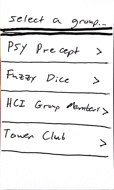
The user can create groups of people which they want to be quizzed on:

F1

Using the Princeton database, students’ names and photos can be added to the application for quizzing (this would probably have to be approved using a student ID). Either name to face matching or face to name matching are available in this application

F2

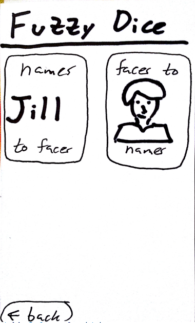
Name matching shows a name which the user has to visualize

F3

And the user can see the face to ensure that they are thinking of the right person. Names can also be skipped if the user knows them and doesn’t need to be quized

F4

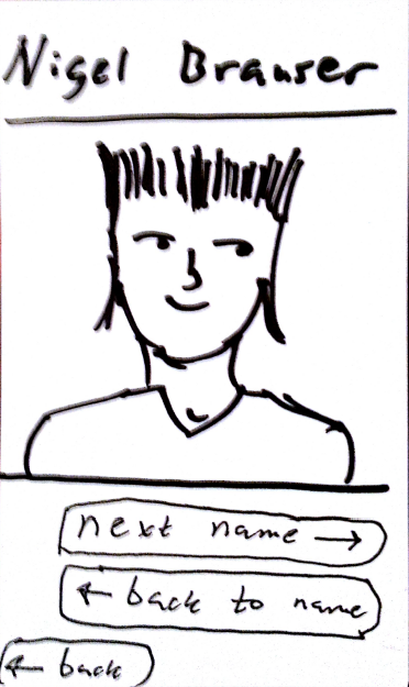
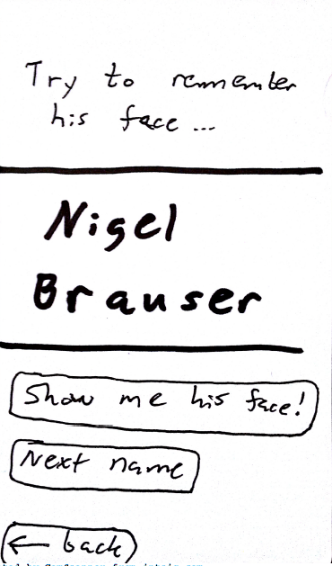
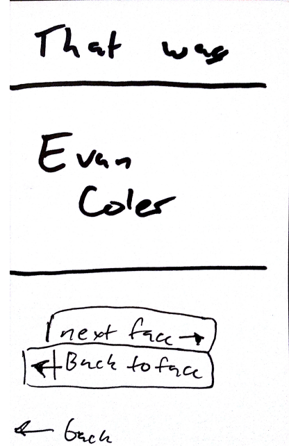
Face to name recognition will show a face and ask the user to think of the name

F5

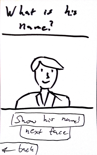
Similar to name to face recognition the user can skip faces

F6

As an expansion on this project, the application could track names and faces which the user marks as “hard” and will show those names and faces more often until the user marks them otherwise.

Note Cloud: Effectively skim your notes


People want to review their notes, but only what is important – skimming doesn’t really get the job done effectively and this application shows you the weight of different topics from the previous class; it’s great for those who type their notes so they can select words within the cloud and find instances of those terms.

Here’s how it works:

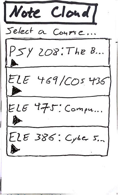
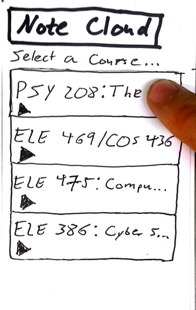
Students add classes which they are a part of and can select particular classes they want to review

NC1 NC2

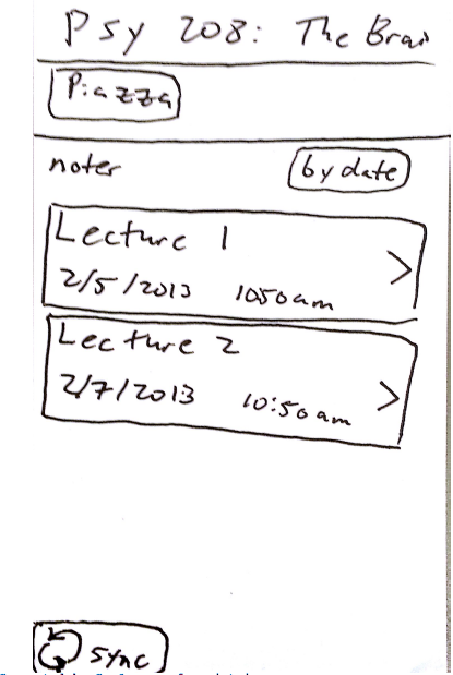
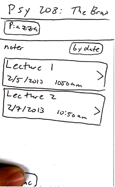
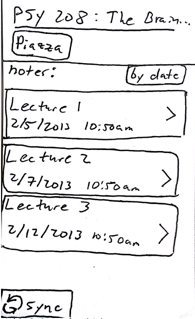
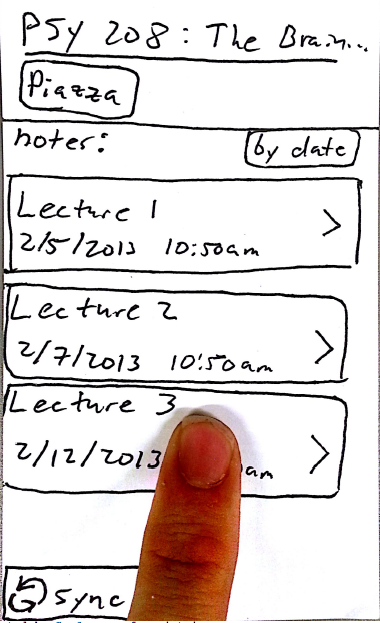
Lecture notes sync online to allow user to access them on their phone – these are typed notes which the user has taken while typing. Below we can see an example of “Lecture 3” becoming available after manual sync

NC3 NC4 NC5 NC6

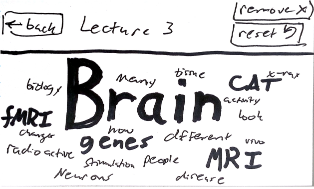
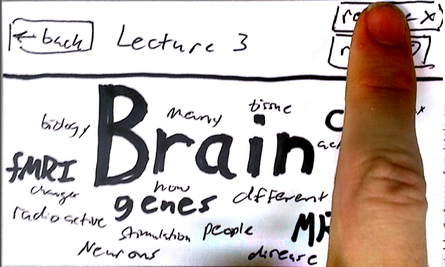
Selecting a lecture shows a word cloud of important terms from that lecture.

NC7

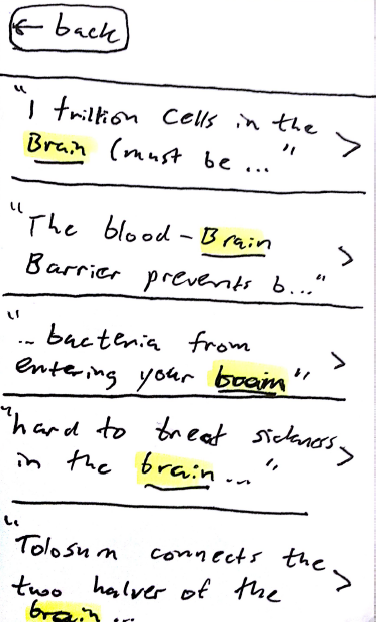
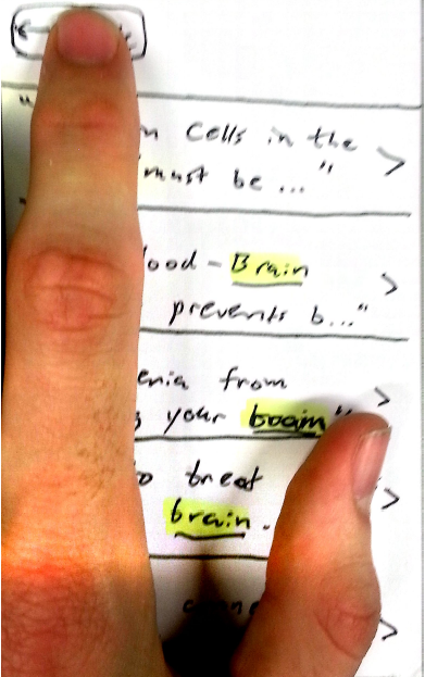
By selecting a term from the word cloud, the user can see all instances of where that word appears in their notes. By selecting the instances, they can see their full notes and what they wrote about that term (this also allows full note browsing with the term highlighted)

NC9 NC10

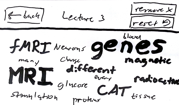
If students want to remove items from the word cloud temporarily in order to see the second most relevant terms they can do that as well.

NC11

NC12


Feedback

The word Cloud prototype was tested on several subjects (Some who were even in PSY 208) Subjects included Dan Steurer, Erica Sollazzo, and George Touloumes.

–          Without prompt, users were able to figure out that the application is used to jog their memory about key concepts from previous lectures which they had taken notes on. The interface was intuitive enough that they could figure out what was happening.

–          A prompt to tell people that they can click on words to see instances of them in their notes would be helpful,

–          Users were unsure of why they would use the remove function to narrow down the word cloud (they may be capable of ignoring larger words on their own)

–          Users wanted a way to search for multiple words at the same time – perhaps a drag and drop option to select your words then “GO!” to see shared instances of them

–          Users wanted to be able to add to their notes (a text editor which will also sync with their notes)

–          Users were concerned that coordination with lecture slides may be lost (many users take notes in power point) the application should be made compatible with power point slides

–          Two users immediately identified that this application syncs with notes in the cloud because of the presence of a sync button (and perhaps the hint from the title “note cloud” which could refer to the word cloud generated or the fact that notes are stored in the cloud)

In summary, I think that either of these applications could be a potential success and user feedback has certainly given me more directions to expand.

A Game of Simon Sees

Group members:

David Lackey – dlackey@

John O’Neill – jconeill@

Horia Radoi – hradoi@

(Santhosh Balasubramanian)

Playing Simon Sees

The aim of our project was to create a wearable version of the classic game of Simon Says. As such, the goal of Simon Sees is to remember and duplicate the sequence of lights generated by the microcontroller. The player wears a pair of glasses with two lights, one on each side, which are diffused via straws to create a visible beam of light. The game begins by showing a light sequence of length 1, which the player must duplicate by pressing the corresponding buttons – lighting the straws to indicate his or her decision. After each successful level, an additional light is added to the sequence. When the user makes a mistake, a red LED light notifies the user, and he or she has to restart the game. Overall, we found our final implementation fairly successful, especially after decreasing the time between the lights in the sequence, which increased the amount of attention needed by the player. After spending time with our prototype and inviting additional users to participate, we discovered that future iterations should contain more than two sources of input/ouput and that the current interface for user input (two buttons) could be transformed into something more engaging and unique, such as auditory- or motion-based forms of interaction.

Click here to view our project in action!

Initial Design Sketch

Initial Design Sketch

IMG_20130213_230037

The Simon Sees interface. Note the red light used to notify a user when they make an incorrect move.

Players use the controller to indiciate which light they think is next in the sequence.

Players use the controller to indiciate which light they think is next in the sequence.

Additional Designs

1. Contextual Disco Ball

If our disco ball senses a low-light environment, it begins increasing the brightness of our LED’s (one red, one green, one blue,) which are placed inside of a semitransparent ball. The lights are pulsating, and the frequency at which these lights pulsate is determined by an interactive Processing interface.

sketch_ball

2. Slit Experiment

Using an LED light and a dark box with two thin vertical cuts in one side (at a known distance), generate an interference pattern on a wall by turning the LED light on inside the black box and pointing the side with the two cuts towards a wall (requires a dark room).

Page-01

List of Parts

  • 1 Arduino
  • 2 Breadboards
  • 2 Buttons
  • 3 LEDs (1 blue, 1 green, 1 red)
  • Alligator clips
  • 1 Pair of glasses
  • 2 Straws

Instructions

  1. Begin by properly placing the circuitry elements on the Arduino board. One button, which is used to trigger the left light, must use pin 13 and should be arranged to a schematic similar to that as described in the Arduino blogs. The button for the right light should be using pin 12. Our left, right, and red LEDs should be using pins 10, 11, and 9, respectively.
  2. In order to attach the LED’s to the glasses, use long wires that have been braided together. These allow us to alter where we place our LEDs while being fairly unobtrusive.
  3. Place LEDs in straws and tape them to the corresponding side of the glasses.
  4. Load the Arduino with the following code, observe the first light in the sequence, and copy – enjoy!

Code

/*
 Simon Says
 Repeat the sequence of lights given by the button inputs.
 */

// Constants 
int N = 10;
int RED_LED = 9;
int LEFT_LED = 10;
int RIGHT_LED = 11;
int LEFT_BUTTON = 13;
int RIGHT_BUTTON = 12;
int DELAY = 200;
int RED_DELAY = 1000;
// State variables
boolean isShowing; // Are we showing lights?
boolean leftLights[10]; // Each element is true for left, false for right
int i; // leftLights index
int level; // Game level

// the setup routine runs once when you press reset:
void setup() {

 // LEDs
 pinMode(RED_LED, OUTPUT);
 pinMode(LEFT_LED, OUTPUT);
 pinMode(RIGHT_LED, OUTPUT);

// Buttons
 pinMode(LEFT_BUTTON, INPUT);
 pinMode(RIGHT_BUTTON, INPUT);

// Init game
 reset();
}

// Reset game
void reset() {
 i = 0;
 level = 1;
 isShowing = true;
 generateLights();
}

// generate lights array
void generateLights() {
 randomSeed(analogRead(0));
 for (int j = 0; j < N; j++){
 leftLights[j] = random(0, 2);
 } 
}

// the loop routine runs over and over again forever:
void loop() {
 if (!isShowing) {
 checkInput();
 }
 else if (i < level && level <= N) {
 showLights();
 }
 else {
 // Stop showing lights
 isShowing = false;
 i = 0;
 }
}

// Check player input
void checkInput() {
 // Collect input
 int leftButtonState = digitalRead(LEFT_BUTTON);
 int rightButtonState = digitalRead(RIGHT_BUTTON);
 // Check
 if (leftButtonState == HIGH && leftLights[i]) {
 // Left hit
 i++;
 show(LEFT_LED);
 }
 else if (rightButtonState == HIGH && !leftLights[i]) {
 // Right hit
 i++;
 show(RIGHT_LED);
 }
 else if (rightButtonState == HIGH || leftButtonState == HIGH) {
 // Miss
 show(RED_LED);
 reset();
 }

 // Check level completion
 if (i == level) {
 i = 0;
 level++;
 isShowing = true;
 }
}

// Show lights
void showLights() {
 // Show lights
 if (leftLights[i++]) {
 show(LEFT_LED);
 }
 else {
 show(RIGHT_LED);
 }
}

// play light
void show(int led) {
 int d = DELAY;
 if (led == RED_LED) {
 d = RED_DELAY;
 }

 digitalWrite(led, HIGH);
 delay(d);
 digitalWrite(led, LOW);
 delay(d);
}

Lab 0: RGB Whack-a-Mole


We designed an RGB version of the ever-popular Whack-a-Mole game using a single multicolor LED, some buttons, and good old Arduino. We wanted to create something entertaining and interactive, that similarly allowed us to explore coding on the Arduino. At first, we envisioned a game with multiple LED’s, but then decided that playing the game in response to different colors in a single light was much more interesting than responding to the turning on or off of lights. Our second revision imagined the multicolor LED starting out as fully lit (white light), and then having components of the light drop out with the player having to press buttons to restore those color components. We liked the dual challenge both of reacting quickly and having to determine which color component was missing, but when playtesting we found that this latter aspect of the challenge was more frustrating than enjoyable for the player. Our final version lights up the LED with one of the three colors behind the diffusion screen and rapidly begins to dim. If the player either fails to respond in time or presses the wrong button, the light will go white, signaling GAME OVER! We are overall quite happy with how the game turned out, and how it helped us play around with the Arduino. The game is fun and completely customizable in just about every parameter. However, we had very few materials with which to construct the physical exterior of the game, so the prototype itself is somewhat of an eyesore.

Team Members: Joseph Bolling, Evan Strasnick, Aleksey Boyko, Jacob Simon

List of Parts:

  • Arduino Uno
  • Pushbutton style switches (3)
  • Tri-color RGB LED
  • 330Ω resistors (3)
  • Wire jumpers
  • Prototyping Breadboards (2)
  • Cardboard
  • Scotch tape

Instructions:

To create your own RGB Whack-a-Mole game, take a look at the circuit included above as a reference.  For the switches, use basic push-buttons.  Note that we chose to place our buttons on a separate breadboard from our tri-color LED, so that we would have a rudimentary controller and output device setup.  Connect the button that you’d like to correspond to the red color to pin 4 of the Arduino, the button that you’d like to use for blue to pin 7, and the button that you’d like to use for green to pin 10.  The red, green, and blue led leads should connect to pins 3, 6, and 9, respectively.

Label your buttons with the color they control, and make a cover for your LED so that the wiring is protected and hidden.  We used simple cardboard and some scotch-tape to make a window for our LED.  Then, upload our code to your Arduino and have fun!

Diagrams:

RGB Whack-a-Mole Circuit — This is the idea we implemented.

WhackAMole

Binary Calculator Circuit — This would allow the user to perform simple arithmetic.

BinaryCalculator

Color Selector Circuit — This would allow the user to create any color by selecting its RGB components.

Sketch 3 - Color scaler

Arduino Program:

// :::::::::::::::::::::::
// Lab 0
// COS436 / ELE469
// Trichromatic Whack-a-Mole / Color Blindness Reflex Test
// Group participants: jbolling, jasimon, estrasni, aboyko
// :::::::::::::::::::::::

// :::::::::::::::::::::::
// INPUT PINS
// :::::::::::::::::::::::
int r_but = 4;
int g_but = 7;
int b_but = 10;

// :::::::::::::::::::::::
// OUTPUT PINS
// :::::::::::::::::::::::
int r_pin = 3;
int g_pin = 6;
int b_pin = 9;

// :::::::::::::::::::::::
// INITIAL COLOR VALUES
// :::::::::::::::::::::::
int r_v = 0;
int g_v = 0;
int b_v = 0;

// :::::::::::::::::::::::
// DIMMING PARAMETERS
// :::::::::::::::::::::::
boolean dim_on = false;
int dim_delta = 0;
float dim_factor = 1;
int dim_ch = 0;
int counter = 1;
int score = 0;

// :::::::::::::::::::::::
// SETUP FUNCTION
// :::::::::::::::::::::::
void setup() {

Serial.begin(9600); // Terminal output

// Input settings
pinMode(r_but, INPUT);
pinMode(g_but, INPUT);
pinMode(b_but, INPUT);

digitalWrite(r_but, HIGH);
digitalWrite(g_but, HIGH);
digitalWrite(b_but, HIGH);

// Output settings
pinMode(r_pin, OUTPUT);
pinMode(g_pin, OUTPUT);
pinMode(b_pin, OUTPUT);

Serial.println(“Set up complete”);

reset_state();

}

// :::::::::::::::::::::::
// MAIN LOOP
// :::::::::::::::::::::::
void loop() {
// If no dimming is happening, try to initiate
if (!dim_on) {
Serial.println(“Dim is not on”);
dim_on = initiate_dimming();
}

int io_code = factor_input();
if (dim_on) {
Serial.println(“Dim is on!”);

// see if input stops dimming
if (io_code != 0) {
// no user input
dim_more();
} else {
// correct input
counter++;
reset_state();
}
} else {
reset_state();
}

// set the diffuser output
analogWrite(r_pin, r_v);
analogWrite(g_pin, g_v);
analogWrite(b_pin, b_v);

delay(100);
}

void reset_state() {

// Reset color values
r_v = 0;
g_v = 0;
b_v = 0;

// Turn dimming off
dim_ch = 0;
dim_on = false;
}

boolean initiate_dimming() {

// Choose a random color
dim_ch = random(0, 3);

// Turn that color on, full brightness
switch (dim_ch) {
case 0:
analogWrite(r_pin, 255);
r_v = 255;
break;
case 1:
analogWrite(g_pin, 255);
g_v = 255;
break;
case 2:
analogWrite(b_pin, 255);
b_v = 255;
break;
default:
break;
}

// New dimming factor
dim_factor = 1.0 – (counter) / 20.0;

// Terminal output
Serial.print(“\tDimming channel “);
Serial.print(dim_ch);
Serial.print(” with factor “);
Serial.println(dim_factor);

return true;
}

int factor_input() {

// read KEY_DOWN events
boolean r_pressed = (digitalRead(r_but) == LOW);
boolean g_pressed = (digitalRead(g_but) == LOW);
boolean b_pressed = (digitalRead(b_but) == LOW);
// encode input with one value
int in_code = (r_pressed?1:0) + (g_pressed?2:0) + (b_pressed?4:0);

// if any was down wait until all keys are released
while (r_pressed || g_pressed || b_pressed) {
delay(100);
r_pressed = (digitalRead(r_but) == LOW);
g_pressed = (digitalRead(g_but) == LOW);
b_pressed = (digitalRead(b_but) == LOW);
}

// Encode dimming channel in the same way as buttons
int out_code = 0;
if (dim_on)
out_code = 1 << dim_ch;

// Difference between input and output
int input_factor = out_code – in_code;

// If user’s input doesn’t match correct input…
if (input_factor != 0 && in_code != 0) {
failure(); // Fail and reset
}

return input_factor;
}

void dim_more() {
if (!dim_on) return;

switch(dim_ch) {
case 0:
//r_v += dim_delta;
r_v *= dim_factor;
if (r_v < 10) failure();
break;
case 1:
//g_v += dim_delta;
g_v *= dim_factor;
if (g_v < 10) failure();
break;
case 2:
//b_v += dim_delta;
b_v *= dim_factor;
if (b_v < 10) failure();
break;
default:
break;

}

}
void failure() {
digitalWrite(r_pin, 255);
digitalWrite(g_pin, 255);
digitalWrite(b_pin, 255);
Serial.print(“Game over! Score = “);
Serial.print(score);
Serial.println(” Try again…?”);
score = 0;
counter = 1;
dim_on = false;
delay(3000);
}

void light_correct() {
score++;
reset_state();
}

PitchSqueak

Group: Bonnie Eisenman (bmeisenm), Mario Alvarez (mmcgil), Erica Portnoy (eportnoy), Valentina Barboy (vbarboy)

Description: We built a cardboard “robot” that responds to having its hand held and its nose tweaked. When you hold its hand, its heart glows and it burbles in robot-speak. Its nose is a potentiometer which controls the color of its eyes. We built PitchSqueak because we wanted to build a puppy, but we couldn’t with the given materials, so we figured that an interactive robot was a decent second choice. We’re all kids at heart and we like kids’ toys. (Also, we wanted to experiment with the buzzer.) While we don’t have any kids on hand to test PitchSqueak with, we all find him quite delightful, so we judge this project to be a success. Improvements we would include if possible would be making the cardboard construction better, and making the potentiometer easier to turn. Originally we had also envisioned having PitchSqueak respond to having his head petted, using the linear Softpot.

Photo Feb 20, 9 54 27 PM Photo Feb 20, 9 40 22 PM Photo Feb 20, 9 32 36 PM Photo Feb 20, 9 10 10 PM

Photos of sketches:

A mini-weather-station with sensors that record the ambient light and temperature, and periodically tweets them.

A mini-weather-station with sensors that record the ambient light and temperature, and periodically tweets them.

A "musical instrument" whose pitch and volume can be controlled using the Softpot and the potentiometer.

A “musical instrument” whose pitch and volume can be controlled using the Softpot and the potentiometer.

PitchSqueak! An interactive robot/toy whose heart glows and he babbles when you hold his hand. You can also change the color of his eyes.

PitchSqueak! An interactive robot/toy whose heart glows and he babbles when you hold his hand. You can also change the color of his eyes.


Storyboard:

Our storyboard. Little Timmy learns to be nice to people / robots!

Our storyboard. Little Timmy learns to be nice to people / robots!

PitchSqueak in Action:

List of parts:

  • 1 buzzer
  • 1 potentiometer
  • 1 FSR
  • 1 red LED
  • 1 RGB LED
  • 1 breadboard
  • 1 cardboard box
  • Electrical tape
  • Wires
  • Paper
  • 1 Arduino
  • 1 USB cable

Instructions for Recreation:

We constructed PitchSqueak out of a cardboard box. We cut out a rectangle of cardboard for the face, and cut holes for the eyes, heart, and nose. The holes for the eyes and heart were covered with paper to diffuse the light from the LEDs. The potentiometer was placed in the hole for the nose and secured with electrical tape. We then used a second piece of cardboard for a “shelf” between the heart and the eyes, to shield the two LEDs from each other. The red LED was taped to the hole for the heart. Electrical tape was used for connecting the wires to the potentiometer. We then cut out a second piece of cardboard for the body, as well as cardboard arms. We taped the FSR to one of the arms, and then attached the arms to the body. Next we connected the body to the face. We taped the LED for the eyes to the top of the robot’s body, inside. Finally, we connected all the sensors according to our circuit diagram with the breadboard.

Circuit diagram.

Source code:

/* Pitch squeak! */

// Pins:
int greenPin = 10;     // analog pin for the green component of RGB LED
int heart = 7;        // the analog pin for the red LED (heart)
int fsrPin = 2;       // the FSR and 10K pulldown are connected to this pin
int potPin = 0;       // the potentiometer is connected to this pin
int music = 3;        // pin that connects to music

// Input: 
int fsrReading;       // the analog reading from the FSR resistor
int potRead;          // the analog reading from the potentiometer

// Constants: 
int brightness = 255;   // the brightness the LED glows with

void setup(void) {
  // We'll send debugging information via the Serial monitor
  Serial.begin(9600);

  // Set the modes of the pins
  pinMode(heart, OUTPUT);
  pinMode(music, OUTPUT); 
  pinMode(greenPin, OUTPUT);
  pinMode(potPin, INPUT);
  pinMode(fsrPin, INPUT);
}

void loop(void) 
{
  fsrReading = analogRead(fsrPin);
  potRead = analogRead(potPin);
  /*
  Serial.print("FSR reading = ");
  Serial.println(fsrReading);     // the raw analog reading  
  Serial.print("Pot reading = ");
  Serial.println(potRead);     // the raw analog reading
  */
  int greenVal = potRead/4.0; // convert 0-255 to 0-1023
  analogWrite(greenPin, greenVal);

  // Light up heart and make noise if hand squeezed
  if (fsrReading >= 500)
  {
    analogWrite(heart, brightness);
    digitalWrite(music, HIGH);
    for(int i=0; i<10; i++) {
      int r = random(0,255);
      analogWrite(music,r);
      delay(100);
     }
     digitalWrite(music, LOW);
     analogWrite(heart, 0);
  }
  else {
    digitalWrite(music, LOW);
  }
}


P1: EyeWrist

Evan Strasnick, Xin Yang Yak, Jacob Simon, Joseph Bolling

Brainstorming!

  1. Dielectric stimulation – Choreography is hard to communicate and record, teach it to people by stimulating their bodies
  2. For anyone attempting to hobbies, sports, or arts requiring tacit skills (e.g. skiing), a helmet could record the motions and perspectives of the master, and then the apprentice could have this perspective played back for them as they attempt the motions.
  3. Dynamically adapting screen that uses eye tracking to take advantage of foveal resolution / peripheral resolution and thereby optimize resources and space.
  4. Glasses or some form of headpiece that tracks direction of gaze to turn on lights only where a person is currently looking, to conserve energy (or just a cool social experiment)
  5. Bad habits tracker: a basic app combined with select hardware pieces could allow users to select their personal bad habits and collect statistics on how often they occur, as well as give advice (teeth-grinding, snoring, stuttering, etc.).
  6. A patch containing a variety of flex sensors could be applied to any of a number of target areas on patients with bad posture, helping to remind them with simple vibration when they sink into unhealthy positions.20B6BBFD-114B-4E8F-894F-756FBAA22E7A
  7. A flex-sensor based device to be placed on the neck, that stimulates (vibration, dielectric, etc.) students with a tendency to fall asleep during class.
  8. Speech recognition software that reads the users lips (and applies predictive software) instead of listening to an audio stream would allow users in public locations to have text-to-speech input without having to speak to their computer, or could serve as an enhancement to existing audio-based software, or could serve as input for disabled/blind patients.
  9. Door that is gesture-triggered, not just motion-triggered – automatic doors often open even when passersby don’t intend to pass through the door; this could be fixed with a more nuanced interface
  10. An automatic toilet that will never flush while you’re still using it. (heat or pressure sensors)
  11. Integrating an accelerometer component into a watch or wedding ring, allowing users to respond to common prompts instantly and effortlessly (answering/rejecting calls, turning off reminders, etc.)
  12. An alarm that wakes you up using gradually increasing light rather than sound. This not only allows users to wake up more naturally and peacefully, but does not disturb neighbors/roommates.
  13. Track REM periods through eyelids to monitor quality and duration of sleep states.
  14. For anyone who wishes to check time discreetly during class, work, a meeting, etc: a ring, bracelet or other touch-controlled item that can signal with vibrations
  15. Sensors (pressure sensors, proximity sensors) that can be placed around the house to automate the tasks a user must perform in various locations (e.g. turn off lights when pressure in bed registered after a certain time, open blinds by stepping in front of them, etc.)
  16. A device which monitors basic physiological readings (blood pressure, heart rate), and activates severity-determined anxiety prevention steps (from helpful text messages to emergency personnel alerts) to help patients with phobias
  17. 3D TV must be viewed from a specific angle to reach the full effect. We propose glasses that use accelerometers or eye tracking to constantly adjust the TV to the correct viewing angle in real time.
  18. Playing cards visible only to players – each player wears glasses which overlay images on specialized cards currently being held in front of them; other players are not shown these images.
  19. Splitscreen multiplayer that is player-specific, hides other player’s screen
  20. A TV which allows family members to view different channels or programs at the same time, using polarized light and viewing glasses for example.
  21. For improved hygiene in public restrooms, an intelligent toilet that automatically raises or lowers its seat depending on user intention (penis identifier).
  22. Making it easier to observe shabbat by automating common tasks using passive proximity technology.
  23. New types of trackpads which can distinguish and recognize individual fingers for advanced gestures – Modern trackpads are very accurate, but cannot identify which finger is being used; doing so would allow for much more nuanced interactions, shortcuts, etc. with a computer.
  24. Car safety (warning if you don’t check your mirrors and blind spots) – eye tracking software could be used to train new drivers to check their blindspots, one of the harder things to learn when driving.
  25. Phone mouse using visual and accelerometer input – The camera on a modern smartphone could be used with accelerometer data to let users accurately pan onscreen by moving their phone.
  26. Actively heated clothing – Clothing that is actively heated by warmed fluids or another mechanism would maintain body temperature in extremities during winter without adding too much bulk, and could be made smart through temperature sensors and shiver-detection.
  27. Study space noise tracker – It’s difficult to know which public spaces on campus are being used as social areas and which are available for quiet study at any given moment; this could be fixed with noise sensors and a web application.
  28. Dance-based music selection – We could solve the problem of poor party DJ-ing with a system that recognized the dances different dancers are performing and selects songs accordingly.
  29. Dance-controlled music synthesizer – The improvised dance performance is vastly improved by live musicians.  This device would produce a similar conversation between dancer and musician without the inconvenience of finding a live musician.
  30. Anti static phone charger – Harvesting the static electricity that builds up in clothing during winter could help charge small devices and solve a major annoyance.
  31. People who like to do gardening recreationally may not know what kinds of plants their garden soil/climate is suitable for. A device that monitors the soil and climate condition can help the planter figure out what types of plants are likely to do well in the garden.
  32. Dental sensors in dentures/retainers – Basic dental diagnostics such as bacterial populations, enamel health, and tooth position could be assessed using devices implanted in dentures and retainers
  33. Text input for severely disabled patients by touching their tongue to their teeth using a specialized retainer.2013-02-20 21.35.21
  34. A toothbrush that maps out where users reach (and don’t reach) while brushing, allowing them to improve their brushing habits and dental hygiene.
  35. Audiovisual recording buffer device – Allows you to retroactively record moments in your life or lecture by keeping a running buffer of the last few minutes. Allows users to never miss out on a moment of accidental hilarity, without the storage restraints of constantly recording the entire day
  36. Improve bad handwriting with a pen that actively corrects its user with counterbalanced weights.
  37. In some sports, it’s easier to spot bad form if you can see yourself in third-person view. Goggles that allow the athlete to see him/herself in third person while performing the action during athletic training might help to improve form.
  38. Monitoring the food that is being baked in the oven currently requires one to open the oven, but this reduces the oven temperature and requires that the chef always be nearby and alert. An oven camera which streams to a smartphone would allow constant monitoring without interfering with the baking.
  39. Smart microwave oven that both scans barcode of food and figures out how long to cook it, and also adjusts the microwaving plate using pressure sensors to always center food to cook evenly.0ED4EB11-E517-4D0F-9E33-611282A0DA5E
  40. It’s a hassle for hikers/athletes/patients who need to stick to a hydration plan to keep track of their fluid intake. A water bottle that tells you how much to drink would help.2013-02-20 21.40.17
  41. CPR instructor necklace/tattoo – A device worn by populations at risk for cardiac arrest could indicate to untrained rescuers how and where to apply chest compressions for CPR.
  42. Phone EKG patch/heart monitor – People could keep continuous track of their cardiac health by wearing small electrode devices that would communicate warnings to a cellphone or other handheld interface.
  43. Weight-lifting sensor gloves – Gloves with built in pressure sensors and accelerometers could track and deliver statistics on how much work is being done with each arm, to allow weightlifters to more accurately exercise their muscles.6E40A95A-BB52-4DBD-8F29-E6AA5952D046
  44. Customer heatmap for stores/attractions – A manager could track which areas or displays experience the most traffic by using pressure sensors or infrared cameras, and adjust product locations and inventory appropriately.
  45. Diagnostic toilet with fluid and fiber recommendations (tracks volume, frequency, and possibly chemical content)
  46. Eyeglasses that not only darken in bright light, but can accurately adjust to any desired level of light (using a liquid crystal layer, for example).
  47. Ctrl + F for physical books: so that a user could instantly find parts of a book, a piece of hardware with an equipped camera would be adjusted to rapidly flip through the pages of a book and photograph each one, using text-recognition software to compile a digital version within minutes.9B215C8B-1BFA-44EB-A3B3-D0C5A83D1E93
  48. Kinect phantom limb therapy – Kinect could be used to display missing body parts in the mirror image of a user, helping ease phantom limb pain.
  49. “Intelligent mirror” – Kinect system + screen would allow users to virtually try on all of the clothes in a store’s inventory  2591AF79-2DC2-45FD-B285-083FF1AECE3D
  50. Kinect-based application that allows the user to turn their entire body into a musical instrument – e.g. control volume by opening mouth while playing out pitches with arm position – but user could select which parts of their body they wanted to control which elements of the music.
  51. Sonar glove (or infrared glove) – a glove which emits and records a high-frequency sound (or infrared beam), indicating the distance from an obstacle via vibrations and allowing blind users to detect obstacles in front of them.

819E9F45-7678-4F4E-8802-5B9DF7D2278A
9A60F65C-F554-4F5F-AA7D-0DD9B0A2523D


After much discussion, we finally decided upon idea #51, the “sonar-glove” (which may or may not actually employ sonar!) First and foremost, we believed that it would be a product that could completely change the way that the user base (the visually handicapped) faces its daily problems. By being something as inconspicuous as a glove, it would serve the same basic goal as a cane, but would draw much less attention and be far more convenient. By offering an analog scale of vibration frequency, users could know exactly how far away they were from an object, and if they wanted, they could even use more than one in order to scan even greater regions of space around them. Another advantage to this system is its design flexibility. While the idea was originally proposed as a glove, the same system could take the form of a more conventional cane (allowing the propioceptive benefits of this more standard approach), or even be embedded in the users shoes. Similarly, we began by thinking in terms of sonar, but have already begun discussing the advantages and disadvantages of other approaches (i.e. infrared beams). We believe that this idea will allow us to make the most of the experience of iterative design, while realistically culminating in the creation of a prototype that could be nothing short of miraculous for its users.

Target User Group: Our main target user group is the blind and visually handicapped. Of course, there are many other possible applications for this technology (working in dark spaces, assisting patients recovering from eye surgery, etc.), but the blind face daily challenges that make even the most basic of tasks frustrating, not the least of which is simply navigating their environment. As evidenced by the fact that multiple coping strategies already exist (canes, seeing-eye dogs, etc.), safely traversing the world is a demanding task for the visually handicapped – one we believe would be much alleviated by constantly being able to sense the distance of obstacles. Of course, while this is a user group which is not terribly common on Princeton’s campus, we believe it would be perfectly feasible to get user feedback by reaching out to hospitals, assisted-living homes, or other members in the nearby community. We believe it is important for users who actually understand the struggles of a visual handicap to test the system, so we will not simply allow testing to consist of “closing one’s eyes.”

Problem Description: The visually handicapped often use canes or other aids in order to walk about without fear of tripping or walking into an unseen obstacle.  While effective, the cane provides a limited amount of information-the device does not alert the user to an obstruction until they are within a few feet of it, and the information refresh rate of the cane is limited by the speed with which the user can physically sweep it.  What’s more, the cane is noisy and physically intrusive, and can become entangled in objects or other pedestrians.  Our glove would serve instead of or in addition to a cane, and would provide more information while being less

Technical platform: Our technological platform of choice is the Arduino. We chose this because our device needs to be portable and needs to be able to make use of input from the proximity sensors and to control the vibration motors on the glove. It also does not require much computational power. The Arduino would also make it easier for us to quickly iterate on technical parameters of the device such as the sensitivity of the proximity detectors or the intensity of the vibration motors to provide the optimal user experience.

Lab 0: The Wondrous Weather Cube (our very own Companion Cube!)

Team members: Kiran Vodrahalli, Collin Stedman, Raymond Zhong, Dale Markowitz

02/19/2013

We created an Internet-enabled companion cube for your computer, which displays different kinds of information by glowing red or green. Depending on its orientation, and which labeled face is oriented upwards, our companion cube displays either stock readings of the NASDAQ or the outside temperature in Princeton. As the temperature or stock index changes, the Arduino inside the cube fetches updated data from the host computer it is connected to, and modulates the brightness of red and green LED arrays inside. We thought it would be a perfect match for the topic of the first lab, LED diffusors, and that it also makes a useful and elegant desktop accent.

Ideation and Design

We started by thinking about LED diffusers, and found that the most interesting applications for us related to using them to display or convey information. We then considered a number of physical interfaces, including a tree, a panel, and various geometric shapes. We settled on a cube because we expected users to want multiple sources of information from the cube, and we thought rotating the cube was a better interface than configuring it by computer, since it would make use of the different sides of the cube. Since we have some Arduino experience, adding Internet connectivity so the Arduino and computer could talk to each other followed rather naturally.

Construction

We found that there was scrap foam in many different places we looked – the upper levels of the E-Quad, the Architecture building, and Frist among others. We went with that, instead of making our cube out of paper, because foam seemed like an excellent prototyping material. It was easy to cut, already pre-formed into sheets, and most importantly fit together like a jigsaw puzzle, allowing us to assemble the foam simply by pushing metal leads into the joints. Eventually we would want to use a laser-cut enclosure for this kind of box.

Concerns and Conclusions

We would have preferred a better spectrum of colors from our cube, but we did not have enough tricolored LEDs to produce enough light to be visible through our cube. We ran into a number of problems because of the differences in brightness and voltage between red vs. green LEDs and indicator vs. lighting LEDs, but we managed to circumvent most of those because foam was such a great diffusing material and blocked little light. Finally, we observed that the Cube is sometimes slow to respond as we scrape data from the web, because of latency. So, we’d like to make it faster if possible.

We think our companion cube is pretty and works well. If we had developed the cube further, it would have more applications — possibly one for each side of the cube, including email notifications, facebook notifications, etc. — and it would use an orientation sensor rather than photoresistors on each side to figure out its orientation.

Design Sketches

Tetrahedron, Prism, some ideas for functionality

Tetrahedron, Prism, some ideas for functionality


Initial Designs: The Tree of Tweets

Initial Designs: The Tree of Tweets


Perhaps a rotating cube? With a base?

Perhaps a rotating cube? With a base?


More Designs for the Cube

More Designs for the Cube

Initial Design for LEDs inside the Cube

Initial Design for LEDs inside the Cube


LED inside the Cube

LED inside the Cube


Rice paper in the middle, cardboard outside

Rice paper in the middle, cardboard outside


Parts of the Cube

Parts of the Cube

More detailed description of how the cube fits together

More detailed description of how the cube fits together

Dimensions of the Cube Side

Dimensions of the Cube Side


Arduino and Breadboard inside the Cube

Arduino and Breadboard inside the Cube

Circuit Design:

Arduino Circuit for Port 5: The Red LED array

Arduino Circuit for Port 5: The Red LED array


Circuit for Arduino Port 3, the Green LED

Circuit for Arduino Port 3, the Green LED

The photocell input circuit

The photocell input circuit


The Final Product! :


The stock market is going down today :(

The stock market is going down today 🙁


The weather is warmish! (At least, more than 33 degrees F! Winter at Princeton.)

The weather is warmish! (At least, more than 33 degrees F! Winter at Princeton.)

Video:

Our Companion Cube Working!

Parts we used:

4 Red LEDs, 1 White LED,  Green marker, Arduino Board, USB Cable, MacBook Air, Wires, 5.6 KOhm resistor, 560 Ohm resistor, photosensor, glue, styrofoam, breadboard

Tools we used: Wire strippers, Multimeter, Scissors, Razor

We also used some Python libraries, as documented in the code.

How to make your very own Wondrous Weather Cube:

You’ll need the parts given above, as well as the code given on the GitHub repo listed below. Assemble the circuit given in the circuit diagram included above. Hopefully the product should look similar to the picture of the completed circuit provided above. Then, build the cube by cutting the Styrofoam squares as shown in the design pictures. Glue the sides of the foam together. You may have to cut a small hole for the USB cable. Then, put the Arduino into the cube, and connect to a computer. First run the arduino code (weather_nasdaqCube.ino), then run the Python code (cube_handler.py). Flip the cube over to test modes. Voila! You now have your own working Wondrous Weather Cube!

Some sources:

http://apexlogic.net/code-bank/python/pyserial-example/ http://docs.python.org/2/library/re.html http://pyserial.sourceforge.net/pyserial_api.html#module-serial


Documented Source code: https://github.com/kiranvodrahalli/WondrousWeatherCube


Training Aid for Drag Racers

John Subosits

Here are some ideas for the third part of the lab.  Finding a way to make the diffuser useful was difficult.

img001

Click on the picture for a better view.

I decided to build the first idea, a device to improve the reaction times of people who drag race.  Three LED’s, red, yellow, and green were used to simulate the “tree” of lights that is used to signal the beginning of a race.  Several pieces of cellophane tape were used as a diffuser for the LED’s although napkins and a water bottle were also considered.  The red light illuminates, the yellow flashes three times, and then the green light comes on.  When this happens the person using the device pushes and holds the switch button supplied in the kit as they would the accelerator pedal if they were racing.  If they false start, only the red light illuminates while a clean start lights all three lights.  After a few seconds, the sequence begins again.  The system was reasonably fun to play with, and I consider it a success.  Some improvements would be adding additional yellow LED’s to allow them to stay lit for the countdown (more realistic), using a switch that mounts to the breadboard or one that has a form factor like a clutch pedal, and using the computer to report reaction times to track improvements.

Here are some videos of the system in action and a few pictures of its layout.

Video9

Video10

Image8 Image9 Image10 Image11

Parts used:

Yellow, green, and red LED 1 each

330 ohm resistor x 3

10 k resistor

12 mm button switch

Miscellaneous jumper wires and clip leads

Breadboard

Arduino

Instructions for construction:

Connect pins 11, 10, and 9 through independent 330 ohm resistors and red, green and yellow LED’s respectively to ground.  Also connect the switch between 5V and Pin 2.  A 10 k pull-down resistor connected to ground was used on Pin 2.  Clip leads should be used, as the switch does not make good contact with the breadboard.  The code below was used to control everything.

// This code is inspired by the Blink example included with the Arduino.
// Also some inspiration is taken from the Button tuturial available at
// http://www.arduino.cc/en/Tutorial/Button
  int red = 11;
  int green = 10;
  int yellow = 9;
  const int buttonPin = 2;     // the number of the pushbutton pin
  int buttonState = 0;

void setup() {
  // put your setup code here, to run once:

  pinMode(red, OUTPUT);   // sets the pin as output
  pinMode(green, OUTPUT);   // sets the pin as output
  pinMode(yellow, OUTPUT);   // sets the pin as output
  pinMode(buttonPin, INPUT); 
 }

void loop() {
  // put your main code here, to run repeatedly: 
  for (int i = yellow; i <= red; i++) {
    digitalWrite(i, LOW);
  }
  delay(5000);
  digitalWrite(red, HIGH);
  delay(500);
  for (int i = 0; i < 3; i++) {
    digitalWrite(yellow, HIGH);
    delay(150);
    digitalWrite(yellow, LOW);
    delay(350) ;
  }
  buttonState = digitalRead(buttonPin);
  if (buttonState == HIGH) {
    delay(4000);
  }
  else if (buttonState == LOW) {
  digitalWrite(green, HIGH);
  digitalWrite(yellow, HIGH);
  delay(3000);
  }

}

Simon!

Group Members: Matthew Drabick, Adam Suczewski, Andrew Callahan, Peter Grabowski

High Level Description:

For part 3 of the lab, our group decided to build a “Simon” game. Our game setup uses 3 buttons and 4 LEDs. Each button corresponds to one LED and the 4th LED is used to indicate an error. The game starts with the arduino flashing one of the 3 lights, chosen randomly. The user must then press the button corresponding to that light. If the user’s input is correct,  the arduino extends the pattern by one and the user must then match that extended pattern. If the user’s input is incorrect, the error light goes off and the user loses the game. This process repeats until the pattern reaches length 7, in which case the user wins the game.

Our game is mounted a paper plate for support and uses origami balloons to diffuse light from the leds.

Here is a video of the game in action:


High Level Design Process:

We began with brainstorming. Our initial ideas included interactive and non-interactive designs. These ideas included pre-set light display patterns (Morse code or musical patterns), diffusers using various translucent paper and plastic covers, and a binary counter.

We decided to first make the binary counter, as we thought it would be both technically and visually interesting. We also would have the opportunity to use our origami balloon/lantern diffusers which we thought were pretty cool.

The binary counter consisted of two buttons (an increment and a decrement) as well four LEDs to display a 4 bit number. With those four LEDs, we could count from 0 to fifteen, and display a fun pattern on overflow or underflow.

We began by sketching our design and drawing the circuitry. Here are our initial brainstorming sketches:

binary_drawing_1

Drawing of the binary counter interface.

binary_drawing_2

Diagram of the binary counter circuitry.

We then assembled our circuit and wrote the code to power our binary counter (technical details given below). In the end we built this:


After completing the binary counter though, we considered our design choices and thought about what we could do to make our circuit better. After making modifications and iterating through different design choices, we decided that what our circuit was lacking was an interesting method of interacting with the counter.  We liked how the binary counter was interactive; however, it was limited to single presses doing the same thing every time. With this in mind, we considered various ways of expanding on our counter, such as using the counter to select and play one of 16 different pre-set light patterns (which could be Morse code messages or other interesting displays) or to play a game. In the end we decided to create the Simon game described above.

simon_drawing1

An initial drawing of the simon interface

Initial design decisions for Simon included how to organize the user interface and how many lights and buttons to include. We decided to use a paper plate as the body of our game as it was easy to manipulate but also gave sufficient support. We initially planned to make the game with 4 lights and 4 buttons, but reduced those numbers to 3 as we continued in the design process and faced limitations due to the availability of resources and bulkiness of alligator clips.

A look at the alligator clips connecting the leds and buttons to the bread board

A look at the alligator clips connecting the leds and buttons to the bread board

Once the basic layout of the game was implemented, we made gameplay decisions like how long to wait between flashes of light and how long the pattern should be for the user to win. We made these decisions by playing the game ourselves, and by having other people play our game. We also had to work out bugs such as a single button press being registered twice. After trying our game with different parameters, we arrived at our final design.

A top view of the final simon game

A top view of the final simon game

Technical Documentation / Technical Design Choices:

There were 2 main circuit components that we used to power our game: LEDs and buttons (these were used with resistors, as needed). In the first 2 parts of the lab, we became familiar with using LEDs. Helpful information about using LEDs with arduinos is found at http://arduino.cc/en/Tutorial/blink.

LEDs are implemented by creating a connection between an Arduion pin and ground. (Image from arduino.cc/en/tutorial/blink) 

We then looked up how to use buttons with arduino at http://arduino.cc/en/tutorial/button. To use a button, we needed to provide a path from ground to 5v (with a resistor) as well as a path to an input pin to sense when the button is closed.

Buttons are implemented by creating a path between ground, 5v, and an input pin. (Image from arduino.cc/en/tutorial/button)

With an understanding of buttons and LEDs, we were able to get started with the technical side of the design process.

We started by drawing the circuitry for our game. There are four LED’s and three buttons in the final implementation but only 3 leds in the diagram below. The fourth LED is an indicator light for when you incorrectly input a sequence.

simon_drawing_2

An initial drawing of simon circuitry

With these design sketches, we were then able to implement our design on the breadboard and mount the buttons and lights on the plate. Though the organization of wires in our pictures looks complicated, it is essentially 4 leds/resistors connected to a digital input pin and ground, and 3 button/resistors connected to a digital input pin, ground, and 5v.

The wiring of the simon interface.

We did not reach our final design immediately though. Our initial design had the LED’s on the inside; we eventually decided to move them to the outside of paper plate for the final prototype. This allowed the diffusers to fit better and also made room for our center failure indication LED. We also attempted to incorporate a 4th LED/button pair but found we were limited on resources.

With the circuitry in place, we then focused on the physical construction. For the led diffusers, we chose to uses the origami ballons/lanterns that we had used previously for the binary counter. We used these origami instructions to make four balloons out of dum-dum wrappers.

single_lantern

A single origami balloon used to diffuse light.

For the base of the game, we took a paper plate and poked four holes for each button (one for each leg) and a single hole for each LED. We then could insert the switches and LEDs and attach alligator clips to the bottom to make the circuits displayed in the tutorials and our diagrams. By following those design diagrams, we constructed what you see in the picture below.

Wiring of simon interface to arduino

Wiring of simon interface to arduino

As you can see, we have supported the plate with three stationary clamps (“helping hands”). This allows the alligator clips to hang down, making the circuits easy to connect and prevent them from touching accidentally. This also allowed us easy access during debugging. After some cleaning up of our wires we finished our simon design. Here is a walkthrough of the finished project:


How to:

1) After reading over the blink tutorial, connect LEDs to your bread board so they connect to digital input pins 9, 10, 11, and 12, a resistor, and ground.

2) After reading over the button tutorial, connect your buttons to your bread board so they connect to digital input pins 2, 3, and 4, ground and 5v.

Our simon breadboard.

Our simon breadboard.

3) Run some test code on you Arduino. Start by running blink on each led to check that you leds and connections are working. Then, try the button code  to test that each button is working. Finally, upload the code below to check that the simon game works.

4) Construct the base of the game using a paper plate or similar material. Arrange the buttons/leds in the manner shown below with the electrical contacts sticking through the plate.

5) Construct 4 origami balloons to act as diffusers.

6) Move the 4 leds and 3 buttons on your breadboard over to the plate setup one by one by running aligator clips from the plate setup to the breadboard.

7) Repeat set 3.

8) Cover each led with an origami balloon diffuser. Hot glue to balloons to the plate for support.

Hot gluing origami balloon diffusers to leds

Hot gluing origami balloon diffusers to leds

9) You’re done!


The Code:

Our code starts by initializing a random array, with length equal to the number of button presses needed to win. It flashes the first color in the sequence, and then falls into the main loop, continually checking for button presses. When a button is pressed, the Arduino checks if it corresponds to the next color in the sequence. If it is the expected color, it advances the position in the sequence by 1. Otherwise, it flashes the sad face led and resets. When the user has reentered the sequence correctly, the next element is added to the sequence, and the game repeats until the user has succeeded on the maximum level.

The most significant problem we had was single button presses being recognized as double presses. We had trouble eliminating this behavior completely, but found some success by introducing a delay of about 250 milliseconds after handling each press.

Here is the code we used for the project:

const int numButtons   = 3;
    const int buttonPins[] = {2,3,4}; // arduino input pins
    const int ledPins[]    = {9,10,11}; // arduino output pins
    const int errorLed     = 12;

    const int maxLength    = 5;

    int randSeq[maxLength]; // contains randomly gen'd game seq
    int level; // current level
    int numCorrect; // how many pins you've pressed correctly so far
                    // always less than level

    int lastStates[numButtons]; // to check button input

    void setup() {
      victory();
      delay(250);
      resetState();      
      randomSeed(analogRead(0));
    }

    //initialize randSeq with random values between 0 and numButtons
    int makeArray(void) {
      int i;
      for (i = 0; i < maxLength; i++) {
       randSeq[i] = random(numButtons); 
     }
   }

   // flash a given led
   void flashLed (int ledNum) {
    analogWrite(ledNum, 0);
    delay(50);
    analogWrite(ledNum, 255);
    delay(200);
    analogWrite(ledNum, 0);
    delay(50);
  }

  // handle input
  void checkInput(int i) {

    // wrong button was pressed
    if (randSeq[numCorrect] != i) {
      flashLed(errorLed);
      flashLed(errorLed);
      flashLed(errorLed);
      delay(250);
      resetState();
      return;
    }
    // correct button was pressed
    else {
      numCorrect++;
      // check for last button in level
      if (numCorrect == level) {
        // check for last level in game
        if (level == maxLength) {
          victory();
          delay(250);
          resetState();
        }
        // not last level in game
        else {
          delay(500);
          numCorrect = 0;
          level++;
          flashSeq();
        }
      }
      // not last button in level
      else {
        delay(100);
      }
    }
  }

  // determine which button was pressed
  void checkButtons () {
    int i;
    for (i = 0; i < numButtons; i++) {
      int state = digitalRead(buttonPins[i]);
      if (state != lastStates[i]) {
        if (state == HIGH) {
          checkInput(i);
          delay(100);
        }
        lastStates[i] = state;
      }
    }
  }

  // flash the sequence of leds up to current level
  void flashSeq(){
    int i;
    for (i = 0; i < level; i++){
      flashLed(ledPins[randSeq[i]]);
      delay(250);
    }

  }

  // turn all leds off
  void setAllOff() {
    analogWrite(ledPins[0], 0);
    analogWrite(ledPins[1], 0);
    analogWrite(ledPins[2], 0);
  }

  // turn all leds on
  void setAllOn() {
    analogWrite(ledPins[0], 255);
    analogWrite(ledPins[1], 255);
    analogWrite(ledPins[2], 255);
  }

  // flash all leds
  void flashLeds(){
    setAllOff();
    delay(100);
    setAllOn();
    delay(100);
    setAllOff();
  }

  // flash the leds in a circle
  void circle() {
    setAllOff();
    delay(100);
    analogWrite(ledPins[0], 255);
    delay(100);
    analogWrite(ledPins[0], 0);
    analogWrite(ledPins[1], 255);
    delay(100);
    analogWrite(ledPins[1], 0);
    analogWrite(ledPins[2], 255);
    delay(100);
    analogWrite(ledPins[2], 0);
    delay(100);
  }

  // special victory flash sequence
  void victory() {
    flashLeds();
    flashLeds();
    flashLeds();
    circle();
    circle();
    circle();
    flashLeds();
    flashLeds();
    flashLeds();
  }

  // reset for a new game
  void resetState() {
    makeArray();
    level = 1;
    numCorrect = 0;
      // delay(500);
    flashSeq();
  }

  // main loop
  void loop() {
    checkButtons();
  }

Biblio-File by %eiip

Group name: %eiip (everything in its place)
Bonnie Eisenman (bmeisenm), Valya Barboy (vbarboy), Erica Portnoy (eportnoy), Mario Alvarez (mmcgil)

Brainstorming list

  1. Paper that can erase itself, keep track of changes
  2. Paper with real-life version control, you can revert it to a previous state, and it includes backups
  3. Real life version control for room, clothes, etc. organization
  4. Cheap projector for when you can’t alter your surfaces (for decoration)
  5. A bookshelf that keeps track of the books on it by using smart book covers or stickers in the books

    Photo Feb 19, 4 19 27 PM

    Sketch of smart bookshelf

  6. Self-adjusting exoskeleton for people who have to stand up for long periods of time (for under your clothes)
  7. A screen position optimized for a person laying down in bed
  8. A real-time translator that strips your speech of mean comments and makes them nice
  9. Clothing or gloves embedded with sound sensors to facilitate echolocation

    Photo Feb 19, 4 19 50 PM

    Sketch of echolocation clothing

  10. Material-free umbrella that repels water using air blowing, possibly.
  11. Clothing that generates electricity from movement and recharges batteries
  12. Hackable clothing that converts energy from motion into changing designs (for fashion options)
  13. A machine that helps you duplicate (scan and print) books licensed under creative commons (or public domain)
  14. Sleep cycle alarm but not based on phone being in your bed; preferably attached to your body

    Photo Feb 19, 4 23 32 PM

    Sketch of sleep cycle alarm

  15. Conductive clothing that generates electricity for keeping you warm

    Photo Feb 19, 4 38 52 PM

    Sketch of conductive warming clothing

  16. Real-time autotuning for vocal cords
  17. EZ-pass for real life: getting into dining halls, or even concerts, etc: a system that scans your ID automagically and also photographs people whose IDs aren’t working

    Photo Feb 19, 4 39 00 PM

    Sketch of EZ-pass for people

  18. Rigorous rock band vocals where it tells you if you do something wrong, and helps out when you’re doing it wrong (for vocal training)
  19. Theatre lighting board user interface; automating; virtual stage
  20. Hair cutting machine like in chitty chitty bang bang
  21. Pockets or bags that keep track of what’s in them

    Photo Feb 19, 4 19 38 PM

    Sketch of smart bag

  22. 3D printing for clothing
  23. Smart binder that scans and keeps track of the papers in it, or automatically digitizes them → integrate web and paper → e-ink on binders (you could display the syllabus and everything else)

    Photo Feb 18, 12 19 21 AM

    Sketch of smart binder

  24. Hoods with heaters so you don’t look like a criminal while keeping warm in the winter, or other invisible heated clothing (for face)
  25. Prox or other chip required to open laundry door in order to prevent theft.
  26. Robots that automatically declog the hair from your drain.
  27. Plant that notifies you when the soil is dry
  28. Litterbox that alerts you when it needs to be cleaned
  29. A way to alert you when you’re grinding your teeth — a cover for your molar that vibrates etc when you grind your teeth?
  30. Portable gas chromatographer–mass spectrometer for detecting allergens in air and food
  31. Flex sensors in gloves to determine how often you’re clenching fists / are stressed, and tell your doctor
  32. Ping pong balls that record their speeds
  33. Smart ping pong table that tells you if it’s in bounds
  34. Chessboards that highlight good next possible moves for teaching
  35. Cheap nighttime illumination: sticker with light sensor and LED for dark glow
  36. Convert human body language to text or visual information that can be sent during electronic remote conversation
  37. Force human hand muscle contraction or flex sensors and motors in a glove to teach sign language
  38. Force human hand muscle contraction or flex sensors and motors in a glove to teach kids to write
  39. Portable self-inflicted electroshock conditioning for improving learning speed
  40. A gestural interface for manipulation of 3D models.
  41. 3-D mouse for manipulating 3-D models, etc. → possibly using a cube with viscous liquid, or a device with an accelerometer, or hacking an optical mouse (preferably that also works in 3D)
  42. Curtains / blinds that open and close based on incoming light and normal use patterns (like the Nest does for temperature – save on lighting, help temperature like Icahn)

    Photo Feb 18, 12 24 27 AM

    Sketch of automatic blinds

  43. Throwing teacher: sensor on object being thrown, calculate what to fix, and inform the thrower. Like frisbee, football.
  44. Smart clothes that inform you when they don’t match
  45. RemberRings – small (wearable!) rings that you can use to record to-dos; press a button to record an idea or play back the recording
  46. GPS + FLORA: embed a GPS in your doggie sweater, so you can keep track of your dog via GPS instead of implanting a microchip, since that freaks some people out. Or, you know, secretly put one in your kid’s jacket.
  47. Auto-sensing LifeAlert: like LifeAlert, a necklace you wear, but this one measures your pulse, and alerts your doctor and / or family if your heart stops?
  48. Wearable GPS: tracks your location, points or nudges you in correct direction for your destination. Could be a bracelet, ring, etc.
  49. Universal car remote to start car and turn on heat
  50. Bike lock that sabotages bike if you dont unlock it (less bulky than a normal lock, hopefully)
  51. Wine bottle reusable cork that determines if wine has gone bad (oxygenation sensor?)
  52. “Windshield wipers” for automatically and quickly erasing chalkboards/whiteboards during a lecture
  53. A programmable teapot that has the hot water ready for you, based on the time you’ve set your alarm for in the morning.
  54. A camera that gets facial expressions of kids in classrooms and somehow alerts teacher when class is confused, bored, etc, so that they can adjust speed

Project choice: Biblio-File

To choose our idea, we each picked two ideas from the list, compiled them into a short list, and we cast three votes (indicated by *) each amongst these top 8 ideas (bookshelf****, echolocation***, automatic blinds*, smart binder *, smart bags *, real life EZ pass*, sleep cycle alarm, self-warming clothing*). We chose to implement a bookshelf that keeps track of the books in it. It is an example of embedded computing as it is based around physical books and the shelves they are on, although we may choose to incorporate an application in addition. It addresses a real-world problem, as it addresses the problem of locating, organizing, and keeping track of books, although the problem really extends to physical objects in general. As elucidated below, it has a specific target group of users. We feel that we can create a prototype between now and May, on a relatively limited budget. Many of our other ideas were too large in scope, did not address a problem that we felt actually existed, or simply did not excite us as much.

Target user group

Our target user is a person who owns a lot of books and ideally has some disposable income. Let’s call our target user Jane. She in a sixty-year-old professional with a large book collection, somewhere between 20 and 500 books, and a voracious reader. She has a bit of arthritis and hates searching for books on her bookshelf. She needs to find books quickly, and doesn’t want to waste time micromanaging and organizing her book collection. She also hates “losing” books that she already owns because she can’t be bothered to search through all of her books. We are not really concerned with libraries, which have specific and perhaps idiosyncratic needs, or book collectors, who may be unwilling to modify their books.

Photo Feb 19, 4 55 43 PM

Jane, an elderly voracious reader

Problem description and context

Imagine a person with lots of books. It could be a college student, a professor, a senior citizen, and/or a bibliophile. When the user goes to look for a specific book, it might be time-consuming and very difficult to find. The user might have to bend over, look in the same place multiple times, or even fail to find it. He might not remember whether he put this particular book on his bookshelf at home or in his office. Maybe he lent this book to a friend, and doesn’t even currently have it. The consumer does not really have the time to reorganize his books, and cannot remember where he put what. Our bookshelf would solve these problems by remembering the books that are in it, as well as where on the bookshelf they are, and allowing the user to search for a book in a given shelf. As far as we know, based on Googling the problem, no related or complementary solutions exist already.

Photo Feb 19, 4 55 48 PM

Professor Dave, our absentminded user

Justification of the technology platform

We’ve chosen to use the Arduino microcontroller platform to implement this project. We believe the Arduino is the most appropriate because of its low cost, its ability to interface with low-level electronics (such as our indicator LEDs), and its compatibility with a wide array of sensors. This last is important because we are not yet exactly sure how we will implement sensing the locations of books, and we don’t want to limit our options. Add-ons for the Arduino enable it to have network connectivity (such as this one), which will be needed for the system to look up books based on their ISBN bar-codes. Additionally we need to create an interface for users to input information about the books they’re trying to find, so the system can help them find it. This could be a web app, a mobile app, or even a screen/keyboard built into the bookshelf unit.

Bedside Floral Lamp

by Farhan Abrol (fabrol),  Kuni Nagakura (nagakura@), Yaared-Al-Mehairi (kyal@) and Joe Turchiano (jturchia)

Concept:

For our diffuser, we designed an authentic tri-color Bedside Floral Lamp. The lamp was constructed from tree branch (spine of lamp), CD casing (base of lamp), six single-colored LED lights (red, green, and yellow), several wires, 6 short-size rolling papers, strips of aluminum foil, and a hot glue gun. Three potentiometers control the LED lights on the lamp (one for red, one for green, and one for yellow). When users wish to turn the lamp on, they simply twist the potentiometers to increase the brightness of the potentiometer’s corresponding color. With the LED lights on, the rolling papers, i.e.  ‘light shades’, act as effective diffusers, which combined with the reflective strips of aluminum foil create visually attractive light patterns. Users can modify the lamps color and brightness with the potentiometers to set the appropriate mood. When users wish to turn the lamp off, they simply must reset the potentiometers, which turns all the lights off.

We decided to build a tri-color Bedside Floral Lamp because we wanted to create an aesthetically pleasing light source that users could tune to their mood. Conceptually, the LED lights represent the seeds of the flower and the aluminum strips the petals. Collectively, we are pleased with the result of our design. We especially like the addition of aluminum strips, which enhances the light diffusion process and therefore creates even more optically enjoyable effects.

One problem with our design though is that the aluminum strips are not rigid enough, and so tend to keep falling down, thereby failing to reflect the LED lights. An improvement that could be made would be to add some kind of support to the aluminum strips to keep them in place, and therefore acting as effective reflectors.
At first, we tried to build a Bedside CD Lamp because we thought CDs would be effective diffractors of light. It turned out that due to the limited power of our LED lights, CDs would only create a rather underwhelming light diffusion effect.

Design:

Through our design process, we considered 3 prototypes. Of these sketches, we actually conceived 2 of our prototypes and ultimately decided on our final design.

We began with the idea of the lamp and considered various ways to diffuse the light. Our first two prototypes used CDs to diffuse the light and our final prototype makes use of rolling papers and aluminum foil.

2013-02-06 21.43.39

Initial rough sketch for our first prototype

This initial model was discarded because of structural issues. The 8 CDs would not stay together without adding additional structural supports. Our second prototype, which incorporates 3 CDs instead of 8 simplifies the structure of our lamp.

We finished building our second prototype; however upon testing in various lighting conditions, we decided that the CDs were not adequate diffusers for our LED lights. Thus, for our final prototype, we chose to use different materials for our diffuser, and our final design incorporates rolling papers that wrap around the LED light and aluminum strips that surround the lights. A potentiometer that corresponds to the 3 sets of LED lights (red, green, yellow) give the user control over the mood and color of the lamp.

photo (1)

Sketch of prototype 3

Final design sketch

photo (2)

3 Potentiometer for each color (red, green, yellow)


The Finished Prototype

2013-02-18 18.27.14

Close-up of the diffuser

Yellow LED's

Yellow LED’s

Red LED's

Red LED’s


Green LED's

Green LED’s


Demo:

Parts List:

  1. 6 LED’s (20mA, 2V) – 2 red, 2 yellow, 2 green
  2. Green and Brown insulated copper wire
  3. 3 Compact discs
  4. 1 Flex sensor
  5. Pack of short-size rolling papers
  6. 1 roll Aluminium foil
  7. 3 rotary potentiometers
  8. 1 Tree branch for support
  9. CD-holder base (or similar rigid base)
  10. 1 Soldering iron
  11. 3 Alligator clips
  12. 1 Glue gun
  13. 1 Arduino board

Instructions:

  1. Start by gluing the wires that will connect the led’s from the top of the branch to the Arduino. Glue the brown wires first. Run the wire along the side of the support leaving about 3″ at the top and about 6″ at the bottom extra for making electrical connections. Then wrap the green wire around these wires and glue it, again leaving extra wire at the ends for connections.
  2. Cut a hole in the center of the CD-holder base and run all the wires through it. Make the support stand upright on the base and glue the bottom to fix it in position.
  3. For each pair of LED’s of the same color, solder the negative of one to the positive of the other. These pair’s will act as the building blocks for the LED pattern at the top of the support. Strip the ends of all the wires at the top of the support. For each pair of LED’s, connect the positive end to one of the brown wires and the negative end to the green wire (which acts as ground). Make a note of which brown wire connects to which color.
  4. Connect the other end of the wires to the Arduino pins through a 330 ohm resistor in series with each, in the following manner –
    Red LED’s – Pin 9
    Green LED’s – Pin 10
    Yellow LED’s – Pin 11.
  5. Make conical light shades using the rolling papers and cover each LED with one conical shade.
  6. Cut out 6 – 5″ X 1″ strips of aluminium foil and layer them to make each strip stiffer. Then, attach each of the strips around the support in a floral pattern, with the bottom end taped below the LED’s and the upper ends hanging loose.
  7. Attach the leftmost pin of each potentiometer to ground, and the rightmost pin of each to 5V. Attach the middle pins to A0, A1 and A2 for yellow, green and red led’s respectively.

Source Code:

/* Radiate
* Group: Yaared Al-Mehairi, Kuni Nagakura, Farhan Abrol, Joe Turchiano
* ------------------
* The circuit:
* LED's (red, green, and yellow) are attached from digital pins 8, 9,
* and 10 to ground. We connect potentiometers to analog in pins 9,10,11.
*/

// These constants won't change. They're used to give names
// to the pins used:
const int analogInPinY = A0; // Analog input pin that the potentiometer is attached to
const int analogInPinG = A1; // Analog input pin that the potentiometer is attached to
const int analogInPinR = A2; // Analog input pin that the potentiometer is attached to

const int analogOutPinY = 9; // Analog output pin that the LED is attached to
const int analogOutPinG = 10; // Analog output pin that the LED is attached to
const int analogOutPinR = 11; // Analog output pin that the LED is attached to

int sensorValueY = 0; // value read from the pot
int sensorValueG = 0; // value read from the pot
int sensorValueR = 0; // value read from the pot

int outputValueY = 0; // value output to the PWM (analog out)
int outputValueG = 0; // value output to the PWM (analog out)
int outputValueR = 0; // value output to the PWM (analog out)

void setup() {
// initialize serial communications at 9600 bps:
Serial.begin(9600);
}

void loop() {
// read the analog in value:
sensorValueY = analogRead(analogInPinY);
sensorValueG = analogRead(analogInPinG);
sensorValueR = analogRead(analogInPinR);

// map it to the range of the analog out:
outputValueY = map(sensorValueY, 0, 1023, 0, 255);
outputValueG = map(sensorValueG, 0, 1023, 0, 255);
outputValueR = map(sensorValueR, 0, 1023, 0, 255);

// change the analog out value:
analogWrite(analogOutPinY, outputValueY);
analogWrite(analogOutPinG, outputValueG);
analogWrite(analogOutPinR, outputValueR);

// wait 2 milliseconds before the next loop
// for the analog-to-digital converter to settle
// after the last reading:
delay(2);
}