L3 – Group 4 (Rumba)

Group 4 – Team TFCS – Collin, Dale, Raymond, Farhan

Short Description

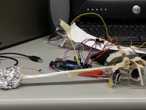
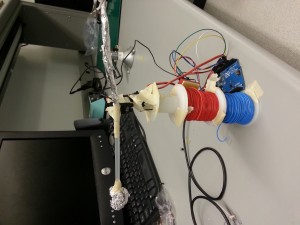
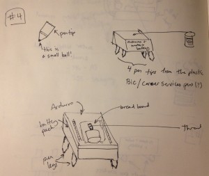
We built a robot consisting of two “feet” connected by a paper towel tube. Each foot was a small breadboard plugged into a row of male header pins. The exposed ends of these pins were all bent at a 40 degree angle in the same direction. A DC motor was secured to the top of each foot, and each motor was attached to a single propeller blade with a small weight at the end. We put our Arduino in a “cockpit” which we built into the center of the paper towel tube. The motors were then plugged into the Arduino, and the Arduino was given a battery pack so that it could run without being tethered to a computer. Our group first decided that we wanted to build a robot that moved by vibration. We were motivated to make this decision because of the inherent weakness of DC motors. We didn’t want our robot to move randomly, however, so we decided to encourage the robot to move in a particular direction by angling the bristles on its feet so that the friction of moving forward would be less than that of moving in any other direction. Then, inspired by the neighboring car lab, we decided to go a step further and make our robot steerable by having two independently running feet. The concept is similar to that of a tank. The final product was viewed as a success. The robot moved as desired, and it could run on its own via battery power. However, it is a little slow. If we were going to redesign it, we would probably want to find a better way to get the feet to vibrate. This would probably involve a different configuration for the motor and its attached weights. We could also come up with a better design for the feet, perhaps using fewer bristles or some material other than metal.

List of Brainstormed Ideas

  1. Toothbrush Rumble Bot
  2. Three-Wheeled Vehicle
  3. Hovercraft
  4. Grappling-Hook Bot
  5. Ladder Crawler
  6. Magnetic Surface Crawler
  7. Segway
  8. Rudder Boat
  9. Fanboat
  10. Hot Air Balloon
  11. Blimp
  12. Hybrid Airship (Blimps connected to propellers)
  13. Flywheel Car

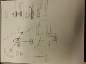
Sketches

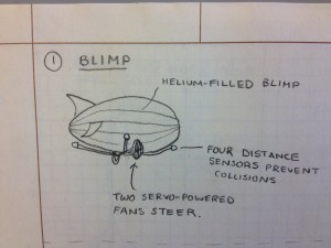
Arduino-powered blimp is filled with helium. Fans on either side of the underbelly control which direction the blimp moves.
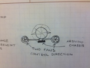
Back view of Arduino blimp.

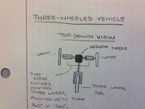
Top-down view of Arduino tricycle.

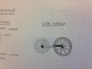
Side view of Arduino tricycle.

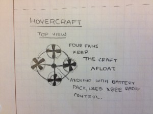
Arduino hovercraft consists of a plastic ring with an Arduino at its center. Evenly spaced around the ring are four fans powered by motors that allow the hovercraft to “hover”.
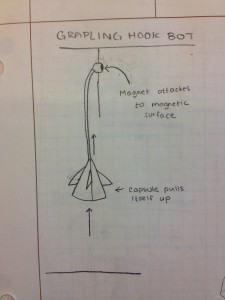
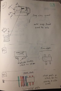
Grappling hook bot launches a ball with a small magnet and rope attached. It attaches itself to a magnetic surface and pulls itself upwards by winding the rope around an axle.

Grappling hook consists of magnet attached to aerodynamic ball.

Air compression tube is compressed by motor and launches the grappling ball. Rope attached to motor axle pulls chassis upward along rope.

Ladder Crawler consists of two hooks attached to telescoping arms. An Arduino moves the arms in and out, and the hooks grab onto each subsequent rung of the ladder.

The magnetic surface climber moves by coordinating its arm movements with the turning on an off of two electromagnets.

This segway consists of two motors attached back to back with an Arduino hanging down beneath them.

This boat uses a servo motor to move a rudder back and forth, producing forward motion.

This boat has a backwards-facing propeller which pushes the boat over the surface of the water.

Manny other robot ideas can be seen here, including the idea we finally selected, the rumble bot.

The Product

It’s Alive

Learning to Steer

From The Robot’s Perspective

A Cool Path

Parts List

-2 Small DC Motors
-1 Paper Towel Tube
-1 Arduino
-Jumper Wires
-Tape
-2 Small Weights (like screw nuts)
-2 Mini Breadboards
-2 Rows of Male Header Pins
-Victory Flag
-1 Battery Pack
-1 9V Battery

Instructions for Creation

a. The premise of Rumba is that its two “feet”, which consist of rows of angled wire, are designed in such a way that when they are vibrated, they move in a direction determined by the angle of the wire. Rumba has two feet connected by a paper-towel-tube body. When the left foot is vibrated and the right foot is not, Rumba pivots around its right foot. Conversely when its right foot alone is vibrated. In this way, we can control which direction Rumba moves in.

b. Thus, in order to make a Rumba, we have to find a way create vibrations. To do this, attach an asymmetric servo horn to the axles of each of two small DC motors. We then attach a very small weight (like a nut for a screw) to the end of the servo horns. When the asymmetric horns turn, they continuously move the center of mass of the system. The result is that the motor vibrates. Securely attach each motor (with strong tape) and servo horn to two mini breadboards so that the servo horn hangs off the side and can rotate freely.

c. Now we must create the angled bristles for the feet of our Rumba, which will be attached to the bottom of the two breadboards. These will be made out of male-to-male headers. For each breadboard, measure one row of headers with enough pins to line the long outer edge of the breadboard. Attach the headers to the breadboard. Bend the pins that are now sticking out of the breadboard to be about 40 degrees from the breadboard. These are the breadboard feet.

d. Rumba’s body consists of a cardboard paper towel tube. Tape both breadboards to either end of this tube so that the angled feet face down, making sure to avoid the feet when taping the breadboard.

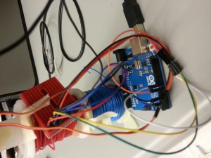
e. The brain of Rumba is an Arduino. Load the code below to the Arduino. It is programmed to turn each motor so that Rumba moves in an “interesting” way. To attach the Arduino to Rumba, first create a square tray chassis from the box that Arduino comes in. Cut a hole in the chassis where the round power plug will attach to a battery pack. To attach the chassis, we cut a square from the *top* of the center of paper towel tube, so that the bottom half of the tube is intact and the chassis can securely slide into the opening  Attach a battery pack (we used a 9V battery pack) to the Arduino and place it along with the Arduino in the chassis. Tape the chassis to the paper towel role.

f. Now we attach the motors to the Arduino, by connecting the power wire to ports 3 and 5, and the ground wire to ground.

g. Turn on the power. Your Rumba should now be functional!

h. Optional: Add victory flag.

Grupo Naidy – L3

Names: Yaared Al-Mehairi, Kuni Nagakura, Avneesh Sarwate, Joe Turchiano, John Subosits

Group Number: 1

Description:

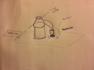
For our creatively moving robot, we decided to build a roomba like bot made out of plastic bottle parts. Our CrackRoomba is driven by a DC Motor which is attached to the end of a punctured bottle cap. The rotor of the DC Motor is positioned underneath the bottle cap and is held in place by electrical tape. While the CrackRoomba in action exhibits creative patterns of motion, at the same time, it serves as a surface polisher. Our main inspiration for the CrackRoomba came from an earlier idea to use a Servo to simulate inch-worm motion. We thought it would be cool to create a robot that could crawl forward using joint motions. However, precise joint motions seemed rather difficult to perfect, and as a result we chose to adapt the traditional roomba with more erratic motion and attach it to a bottle to simulate an edging forward motion. We were certainly pleased with the results of the DC Motored bottle cap. The DC Motor drove the bottle cap rather well and moved extremely smoothly over the table surface, thus acting as an effective looking surface polisher. Although the DC Motor drove the bottle cap well and the whole system edged forward consistently, we would have liked to see more movement of the large bottle. While simply using a smaller bottle could be one improvement, allowing more precise movement of the motorized bottle cap so as to allow the CrackRoomba not only to simply nudge but also to pull the bottle in a steady direction would be something to work on in future iterations. At the moment, the limited motion of the large bottle restricts the area that the motorized bottle cap can polish due to the irregularity of the motorized bottle cap’s movement.

Brainstorming Ideas:

  1. Wobblebot – Weeble-wobble bot that uses eccentric weight to roll (DC motor)
  2. Helibot – Helicopter bot that uses Servo to aim and DC motor to jump in a given direction
  3. Wheelchairbot – Wheelchair bot propelled by DC motor
  4. Breakbot – Breakdancing bot that can do the “windmill”
  5. Trackbot – Drive wheels/tracks with DC motor
  6. Legbot – Construct bot legs out of wheel parts and drive with DC motor
  7. Wormbot – Use Servo to simulate inch-worm motion
  8. Airbot – Controllable airship that uses servo to aim DC motor driving propeller
  9. Clumsybot – Robot that falls over in a desired direction then picks itself up and repeats
  10. Dragbot – Use DC motor as winch to drag bot back to “home base”
  11. Sledbot – Use DC motor to drive fuel pump for engine of rocket sled bot
  12. Trolleybot – A trolley that uses a pulley, a DC motor, and a guiding wire to move
  13. Rollbot – A robot that does a “pencil roll” using a DC motor
  14. Boatbot – A boat with a Servo controlled rudder and DC motored propellor
  15. Cranebot – “Arm and wheel” model where DC motor is mounted on Servo and from computer you can lift and drop Servo to let DC motor touch ground or not
  16. CrackRoomba – Use DC motor to drive roomba made out of plastic bottle parts

We chose to prototype idea #16 – a roomba type bot that polishes floors and moves.

Design Sketches:

2013-03-31 20.13.17

CrackRoomba sketch (bottle cap, DC Motor, large bottle, Arduino, circuitry)

2013-03-31 20.13.25

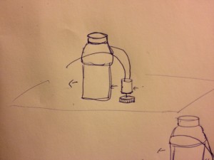
CrackRoomba polishes floor and edges forward

2013-03-31 20.13.30

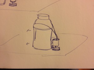
CrackRoomba pushes against bottle, nudging it ahead

System in Action:

Polishing Surface

http://www.youtube.com/watch?v=6eafvjX4VYg

Edging Forward

http://www.youtube.com/watch?v=Abs9HWZJdsM

Polishing Suface and Edging Forward!

http://www.youtube.com/watch?v=lvgPTTrOOVg

Parts List:

  1. Arduino
  2. DC Motor
  3. Bottle Cap
  4. Large Bottle
  5. Electrical Tape
  6. 1N4001 Diode
  7. PN2222 Transistor
  8. 220 Ohm Resistor
  9. Breadboard
  10. Jumper Wires
  11. Alligator Clips

Instructions:

  1. Poke a hole in the center of the bottle cap
  2. Put the rotor of the DC Motor through the bottle cap
  3. Apply some electrical tape onto the rotor to put it in place
  4. Attach alligator clips to the motor’s wires and tape the aligator clip wires to the large bottle
  5. Put the DC Motor vertically onto the table with the bottle cap on the table surface
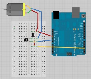
  6. Assemble the circuitry to operate the motor according to the attached diagram
breadboard

Circuit diagram

Source Code:

/*
Names: Kuni, Yaared, Avneesh, Joe, John
Group 1, Grupo Naidy
COS 436 Lab 3
CrackRoomba code
*/

int motorPin = 3;

void setup() 
{ 
  pinMode(motorPin, OUTPUT);
  Serial.begin(9600);
  while (! Serial);
  Serial.println("Speed 0 to 255");
} 

void loop() 
{ 
  if (Serial.available())
  {
    int speed = Serial.parseInt();
    if (speed >= 1 && speed <= 255)
    {
      analogWrite(motorPin, speed);
    }
  }
}


Lab 3, Group 14 (Team Chewbacca) – Catapult

i. Karena
Stephen
Jean
Eugene

ii. Group 14

iii. Short Description

We built a catapult that detects when something is nearby. Upon sensing something, the catapult will launch a small object in the direction of where the thing was sensed. We wanted to make something that reacted to a proximity sensor mounted on a rotating arm, and we thought a catapult was a fun and creative way to have a system that reacted to a nearby object. An inspiration for our project was defense mechanisms, that may be employed in preventing unwanted people or objects from nearing a certain range. Our original plan was to make a robot that moved in the direction of an object that it detected, but after multiple iterations, we could not get the robot to move forward effectively.  The forward motion was not effective because the motors weren’t powerful enough, and the servos would resume to their original position after moving, which canceled the forward motion. In the end, we ultimately decided to launch something at the target instead of moving towards it. With additional motors or materials, we might have been able to achieve our original idea. We thought we were successful in creating a robot that moved in reaction to its surroundings. The catapult accurately launched an object at considerable speed towards the target, and the proximity sensor responded immediately to targets it touched. One improvement we would have liked to make to our project would be to make our proximity sensor more powerful.  Because we didn’t have a 10 MegaOhm resistor, the catapult would only detect an object that was touching the proximity sensor. We would be able to improve our catapult if we had access to this resistor.

iv. Brainstorm
– smart window-blind motor (more light lowers blind using motor, less light raises blind using motor)
– flying robot that increases the motor speed depending on it’s proximity from the ground
– catapult; propels an object at different speeds
– tilt the arduino controller to move the robot
– a segway (with a servomotor fowards/backwards movement controller)
– mono-segway (hard)
– impulses depending on acceleration from accelerometer
–  temperature-sensing fan
– linear sensor with FSR – fsr controls speed, linear controls turning
– line follower/wall avoider
– moves towards light in its field of vision (servomotor wiggles the light sensor from side to side to get the max light reading)
– disk-shooting robot
– sweeping robot – spins around and pushes dirt around
– a top robot – spins around and balances itself
– a two stage system – first catapults itself using a heavy weight controlled by a servo (wires detach from the force), and then moves around
– a paddling robot for land and water
– kicking robot using proximity
– a monocycle – aka hamster bot
– hopping robot
– throw out a bunch of stuff on the robot to push it backways
– advances the lead on a mechanical pencil to push it forward
– inchworm robot (servos)
– underwater propeller
– a rocking robot
– hovercraft – propeller downwards, then another propeler sideways


v. photos of design sketches

20130331_180930 20130331_192759 20130331_192811


20130331_195708-1

vi. video of final system

http://youtu.be/R2p-HGOnCgA


vii. list of parts

  • two servomotors
  • proximity sensor (using tin foil)
  • arduino uno
  • breadboards
      •  
  • a lot of tape
  • wires
  • some cardboard
  • straw
  • foil

viii.instructions

Attach two servo motors to the arduino, and attach these to the straw by attaching one servo to the straw, and the second servo is attached to the first servo. The first servo acts as the “turning servo” which will turn the straw around to look for an object within its proximity, and the second servo  acts as the “shooting servo” to fire the catapult when something is detected.

ix. source code

/*
Adafruit Arduino – Lesson 14. Sweep
*/
#include <CapacitiveSensorDue.h>
#include <Servo.h>
int servoPin = 8;
int servoPin2 = 7;
Servo servo;
Servo servo2;
int angle = 0;   // servo position in degrees
int motorPin = 3;
CapacitiveSensorDue cs_4_2 = CapacitiveSensorDue(4,2); // 10M resistor between pins 4 & 2, pin 2 is sensor pin, add a wire and or foil if desired
void setup()
{
  pinMode(motorPin, OUTPUT);
  Serial.begin(9600);
  servo.attach(servoPin);
  servo2.attach(servoPin2);
}
int readCapacitor() {
  long start = millis();
  long total1 = cs_4_2.read(30);
  Serial.print(millis() – start); // check on performance in milliseconds
  Serial.print(“\t”); // tab character for debug windown spacing
  Serial.println(total1); // print sensor output 1
  return total1;
}
int threshold = 100;
void moveforwards () {
     // scan from 0 to 180 degrees
   int maxangle = 0, maxvalue = 0;
   servo2.write(180);
  // now scan back from 180 to 0 degrees
    maxangle = 0, maxvalue = 0;
  for(angle = 180; angle > 0; angle–)
  {
    servo2.write(angle);
    delay(5);
  }
}
void loop()
{
  // scan from 0 to 180 degrees
  int maxangle = 0, maxvalue = 0;
  for(angle = 60; angle < 180; angle++)
  {
    servo.write(angle);
    if (angle % 1 == 0) {
      int proximity = readCapacitor();
      if (proximity > threshold) {
         moveforwards();
         delay(500);
      }
    }
    delay(15);
  }
  // now scan back from 180 to 0 degrees
  maxangle = 0, maxvalue = 0;
  for(angle = 180; angle > 60; angle–)
  {
    servo.write(angle);
    if (angle % 1 == 0) {
      int proximity = readCapacitor();
      if (proximity > threshold) {
         moveforwards();
         delay(500);
      }
    }
    delay(15);
  }
}


L3 — All Terrain Strugglebot

Members of the Illustrious Group #21: “Dohan Yucht Cheong Saha”

  • Miles Yucht

  • David Dohan

  • Andrew Cheong

  • Shubhro Saha


Short Description

This week we were in a Southern mood in anticipation of Spring Break, so we initially decided to build a LassoBot. This robot throws a lasso in a circle until an object in the lasso’s path is grabbed on to. At that point, LassoBot reels itself closer to the object it caught. Late in development, we realized that making LassoBot hook itself onto stationary was extraordinarily difficult given the weakness of the DC motor. At that point, we switched to building a StruggleBot that constantly rotates a lasso in an effort to move forward in a particular direction. The final product was a great success. The StruggleBot is amusing to watch, as it struggles, and it’s a creative means of locomotion. There were a few initial difficulties while creating our robot.  Our initial plan to create a lasso bot did not work because the DC motors are too weak to reliably pull the robot along (although it did work in some cases).  Additionally, it was difficult to spin up the lasso without it tangling with itself.  Other plans for the “tumble weed” robot fell through because we found that the Arduino is incapable of adequately powering four servo motors simultaneously as required.


Idea Brainstorm

  1. A snake like robot that moves by curling and uncurling

  2. Attach random objects to it and watch it go berzerk

  3. Flying robot that has rotor blade attached underneath

  4. Moves with caterpillar treads made of… banana peels? Newspaper?

  5. Two-wheeled robot, kinda like a segway, but without the balancing complexity

  6. A robotic “hand” that drags itself across the table, as in Toy Story

  7. A robot that throws a lasso rope and rolls the rope to pull itself closer to the hitched destination

  8. A motorboat! Moves across water, obviously

  9. A robot that pulls itself up a table/wall by raveling a spool of rope hanging from a point… like a cliffhanging robot… even attach a person to make it look creative

  10. Slinky robot, that can move up a staircase by throwing a hook onto the next stair

  11. Window-climbing robot… give it suction cups to go up a window

  12. Shufflebot… by design, it rolls 2 steps forward, 1 step back

  13. Tumbleweed bot.  Looks like a hamster wheel, but has servo motors attached around the edges to roll it forward.  Alternatively, have a single servo motor and a counterweight at the center.


Design Sketches


Final Schematic of Strugglebot


Final System Video


List of Parts

1 AC motor

1 330-ohm resistor

1 potentiometer

1 zener diode

1 PN2222 transistor

2 jumpers

1 6-inch length of string

1 inch of wire

1 Arduino UNO

Electrical tape


Assembly Instructions

1. Set up the potentiometer element to control the rate of rotation of the motor. Connect pin 1 with +5V, pin 2 with A0 on the Arduino, and pin 3 to ground.

2. Set up the motor circuit. To pin 3 on the Arduino, connect a 330-ohm resistor, and connect this to the base on the transistor. Connect the emitter to ground. Connect the motor in parallel with a Zener diode, and connect both of these elements in series with the collector.

3. Mount the motor on the bottom of a circuit board using electrical tape, and use two jumpers in the circuit board to elevate the circuit board off of the ground, face down. Make sure the motor is inclined at 45 degrees.

4. Attach a thread to the motor using tape, and to the other end of the thread attach a piece of wire bent into a hook shape.

5. Upload the code, and use the potentiometer to control the rate of rotation.

Final Source Code

int motorPin = 3;
void setup() {
pinMode(motorPin, OUTPUT);
analogWrite(motorPin, 255);
}
void loop() {}

P3 – Team VARPEX

Group Number: 9

Group Name: VARPEX

Group Members: Abbi, Dillon, Prerna, Sam

In this assignment, Sam was responsible for writing up the mission statement and brainstorming prototypes. Dillon was responsible for writing up the discussion of the prototype and brainstorming prototypes. Abbi was responsible for building the prototypes. Prerna was responsible for describing the prototype and how it applies for our tasks.

Mission Statement:

The purpose of this project is to create a prototype piece of clothing which can take input from an MP3 player and create sensations on a user so that the user can feel lower bass tones. The sensation will be generated using vibrating motors. The device should be comfortable and portable. This product will allow users who are unable to generate loud, feelable bass tones for reasons of cost, noise pollution or portability to overcome these obstacles and feel low bass tones. The current design of the system proposed would use a microcontroller to analyse music tones and actuate motors spaced on the user’s chest. The motors will be incorporated into clothing for ease of use and the microcontroller will be battery-powered and portable. The prototype at this stage aims to discover basically how users will react to primitive actuation from the motors (to determine placement and power). This prototype will also aid in the design of the clothing (fit, weight, etc.). The goal of this team is to produce this final product without going over budget. In particular, our focus is on user experience.

Prototype Description

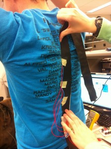
Since our device does not have a visual user interface, we decided to use the lo-fi prototypes to perform further tests on its usability and functionality. With this in mind, we will have two iterations of our lo-fi prototype. In the first iteration, motors will be placed in a band of tape that can be tightly attached to the users body with the motors contacting the user around the spine. This will allow us to test if the motors (and modulation of their intensity) properly replicate the sensation we found users feel in P2. The second portion of our prototype will implant these motors in a loose-fitting sweater. This will allow us to test our form factor- hopefully the jacket offers the user the appropriate level of sensation, but it is possible a tighter-fit will be needed in order to achieve the desired level of intensity.

Use of Prototype in Testing

In P2, we identified the following key tasks of our users:

  • Experience/listen to music without disturbing the quiet environment of the people around you (in the library while studying, in lab, etc.)

  • Experience/listen to music while being mobile (walking to class, in the gym, etc.)

  • Experience/listen to music without disturbing residential neighbors (roommates, suitemates, etc.)

These tasks have informed the characteristics our system needs: proper replication of physical sensations felt from loud speakers and portability. From these characteristics, we’ve determined two fundamental questions we will answer in P4:

  1. Can the vibrating motors replicate the feeling of powerful bass tones from speakers?

  2. Does the form factor of wearing the motors in the jacket produce the proper sensations?

To answer these two questions, we’ll explore user’s responses to the intensity of the motors and the comfort and wearability of motors worn on a loose fitting jacket. Since the differences in our three tasks are linked with the user’s usage environment, and do not differentiate between the actual design of the device, we decided to use P3 to build a prototype that allows us to test the comfort and wearability of the device, as well as test how users feel about the physical locations of the motors in the jacket. This will help us better understand how and where users want to feel the sensations.

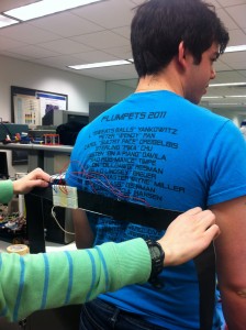
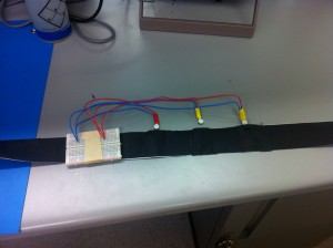
As our mission is heavily dependent on these sensations, a paper prototype or otherwise non-functioning system would not allow us to test anything that would help us see if our proposed system would properly accomplish our mission. At its core, our prototype will have three motors.

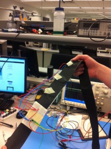
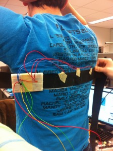
For the first iteration, we will see how strongly the vibrations are conducted through the motors when attached closely to your spine via a tight band. It will allow us to understand how comfortable users are with these vibrations and whether they feel it accurately replicates the live music sensation. In the second iteration, we will attach the motors to a jacket, which will allow us to test for fit, comfort and wearability, which is key to every task we listed above.

Basic Prototype Demo

A Closer Look at the Prototype

IMG_2031

Testing the basic fit of the prototype

IMG_2032

Our prototype – understanding how the motors fit in

IMG_2042

Our prototype – attaching the motors to the band

IMG_2045

Fitting the prototype across the back to test sensations

IMG_2046

Fitting the prototype over the spine to test sensations

IMG_2049

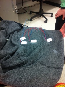
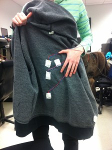
Adding motors to the jacket to test wearability

IMG_2051

Second iteration of the prototype – testing comfort and usability with a hoodie

 Prototype Discussion

Our prototypes required us to implement three of our motors- there is no lower-fidelity method to test our system. We want to test if the vibrating motors at all replicate the feeling users get in going to concerts. Our desired system should also be as ubiquitous as possible. An ideal final product would have the user simply plug their “music-feeling jacket” (or whatever form the product takes) into their iPod, with no interface required at all. This led us to conclude that a paper prototype would not offer us the ability to properly evaluate our system, leading to our implementation of several of our motors.

This made our prototyping process a bit more difficult than we had originally anticipated, since it required us to concentrate more on technical questions that might not otherwise be appropriate at this stage of prototyping (but that we have deemed necessary). For one, how we would power the motors in our prototype became an issue, since it might not be possible to power the motors off of the arduino board due to current limitations. It is these sort of questions that we were forced to wrestle with at an early stage of our prototype. On the bright side, it has forced us to think more practically about what we are hoping to build towards with our prototype.

Group VARPEX – L3

Names: Abbi Ward, Dillon Reisman, Prerna Ramachandra, Sam Payne

Group Number: 9

Description

For this lab we built a robot with four legs that pulls itself along a string. Its four legs are the tips of ballpoint pens, allowing for a smooth gliding motion on relatively frictionless surfaces. Our original inspiration for the robot came from an idea we had to build a robot that opened and closed window shades according to how much light was in a room. This robot would move vertically rather than horizontally, doing so by using a motor to pull itself up a string. We decided to test this method of locomotion horizontally first. We were very pleased with the success of our robot- we did not imagine that it would move so well over the table surface, and in future iterations of this robot we could have it do interesting things in how it moves. The ballpoint pen tips were extremely useful tools for motion along a surface. Unfortunately we do not think the method we used to collect the string once the robot pulled it worked well (we simply wind it up on the end of the motor), and in future iterations we think that the robot should have a way of going one direction on the string, then reversing the motor and going the other direction. In total, however, we think that this method of motion could have many applications.

Brainstormed Ideas: 

  1. Helicopter using paper/cardboard blades
  2. Vibrating robot, moves by vibration
  3. Robot on wheels which uses a fan to propel itself
  4. Arms which rotate similar to single blade propellers to promote movement
  5. Three-legged omnidirectional single plane robot
  6. Worm robot, uses a single joint to contract and move forward
  7. Robot that hits the ground hard enough to “jump” forward
  8. Move the motor foward and reverse direction to hit limbs against ground and propel forward
  9. Use servo to wiggle from side to side and move forward
  10. Robot which eats tape/line of string to move forward
  11. Robot which dances to a beat
  12. High five Robot – moves up to you and gives you a high five if you bring your hand close to it
  13. Acrobat robot – does flips at regular intervals as it moves around in a circle

We chose to prototype Idea 10, a robot which eats a line of string to move forward.

Design Sketches

sketch-1

Assembling the robot, use of the string and using pencils to reduce friction

sketch-2

Using only pencil tips to minimize ground friction, instead of rolling pencils

Demo of our System

Parts list

  • Arduino
  • motor
  • PN2222A transistor
  • Diode (1N4001)
  • electrical tape
  • 4 disposable ballpoint pens (plastic)
  • breadboard
  • 330 ohm
  • battery pack to power the Arduino

Instructions to Recreate System

  1. Build the schematic on the breadboard
  2. Attach the motor to the breadboard with electrical tape

  3. Break open one of the disposable pens into the following parts

    1. the outer tube

    2. inner tube (holds the ink)

    3. tip

    4. ink

  4. Cut off about a 1/2 inch of the inner tube that doesn’t have any ink

  5. Use thinly sliced strips of electrical tape to make ridges on the edges of the tube. This will be used to help keep the thread on the axle so that the robot pulls itself and the thread will not rub against the base of the motor.

  6. Push this tube+tape combo onto the axle of the motor so that it fits snugly.

  7. If leads are showing on the bottom/sides of the battery pack, put electrical tape over them so that loose wires don’t accidentally short power and ground.

  8. Tape the Arduino to the battery pack (the batteries should face the floor)

  9. Cut up the outer tube into ~1 inch pieces and place them on the Arduino.

  10. Tape the breadboard+motor on top of the pen pieces such that the axle of the motor is centered on the robot.

  11. On each of the four pens, take off the tips (with the ink cartridge removed) and tape them to the side/bottom of the battery pack such that the assembly balances and can slide easily across the floor or table.

  12. Use a small piece of electrical tape to attach the thread piece

  13. Hold the spool, upload the code, and the robot will traverse towards the spool

Source Code for the Robot

/*
Names: Dillon R, Prerna R, Sam P, Abbi W
Group 9, Varpex
COS 436 S2013
Our robot code. 
This was just for walking across the table. 
*/

int motorPin = 3;

void setup() 
{ 
 pinMode(motorPin, OUTPUT);
} 

void loop() 
{ 
 int motorspeed = 254;
 //walk a little bit
 analogWrite(motorPin, motorspeed);
 delay(3000);
 // stop
 analogWrite(motorPin,0);
 while(1); 
}


P3 Brisq – The Cereal Killers

cereal_logo
Be brisq.

Group 24

Bereket Abraham babraham@
Andrew Ferg aferg@
Lauren Berdick lberdick@
Ryan Soussan rsoussan@

Our Purpose and Goals

Our project intends to simplify everyday computer tasks, and help make computer users of all levels more connected to their laptops. We want to give people the opportunity to add gestures to applications at their leisure, in a way that’s simple enough for anyone to do. We think there are many applications that could benefit from the addition of gestures, such as pausing videos from a distance, scrolling through online cookbooks when the chef’s hands are dirty, and helping amputees use computers more effectively. In our demos, we hope to get a clearer picture of people interacting with their computers using the bracelet. Brisq is meant to make tasks simpler, more intuitive, and most of all, more convenient; our demos will be aimed at learning how to engineer brisq to accomplish these goals.

Mission Statement

Brisq aims to make common computer tasks simple and streamlined. Our users will be anyone and everyone who regularly uses their computers to complement their day to day lives. We hope to make brisq as simple and intuitive as possible. Enable Bluetooth on your computer and use our program to easily map a gesture to some computer function. Then put the brisq bracelet on and you’re ready to go! Shake brisq to turn it on whenever you’re in Bluetooth range of your computer, then perform any of your programmed gestures to control your laptop. We think life should be simple. So simplify your life. Be brisq.

Our LEGENDARY Prototype

These pictures show our lo-fi prototype of the bracelet itself. Made from some electrical wire twisted together and bound with electrical tape, this allows testers the physical experience of having a bracelet on their wrist while going about the testing procedures.

solo_bracelet[1]

on_hand_bracelet[1]

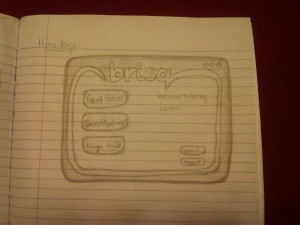
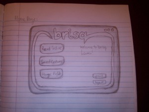
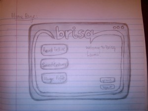
These pictures shows our paper prototypes of the GUI for the brisq software. This software is used as the central program which maps gestures to commands, and remains running as a background process to process the signals sent from the brisq bracelet.

IMG00096-20130329-2112

IMG00097-20130329-2114

IMG00098-20130329-2114

IMG00099-20130329-2114

IMG00100-20130329-2114

IMG00101-20130329-2115

IMG00102-20130329-2115

IMG00103-20130329-2115

IMG00104-20130329-2117

Brisq in use…three tasks


This first video depicts an anonymous user in the kitchen. He is attempting to cook food from an online recipe. Brisq helps to simplify this task by letting him keep one of his hands free, and keeping his distance from his computer, lest disaster strike!


This second video depicts another anonymous user lounging on his couch at home. He is enjoying a movie, but wants to turn up the volume on his computer and is too comfortable to get up. Brisq allows him to stay in his seat and change the volume on his laptop safely, without taking any huge risks.


The last video shows a third anonymous user who has broken her hand in a tragic pool accident. These types of incidents are common, and brisq makes it simple and easy for her to still use her computer, and access her favorite websites, even with such a crippling injury.

Reaching our goal

For the project, we have split the work into 2 main groups: the part concerning the hardware construction and gesture recognition, and the part concerning the creation of the brisq software for key-logging, mouse control, and gesture programming. Bereket and Ryan are going to take charge of the first group of tasks, and Ferg and Lauren will be taking charge of the second. Our goals for the final prototype are as follows: we hope to have a functioning, Bluetooth-enabled bracelet with which we can recognize 4 different gestures, and an accompanying GUI that is capable of mapping these 4 gestures to a recorded series of key-presses or mouse clicks. We think that, with some considerable effort, these are realistic goals for the end of the semester.

P3 — VAHN (Group 25)

Group 25 — VAHN

Vivian (equ@), Alan (athorne@), Harvest (hlzhang@), Neil (neilc@)

1. MISSION STATEMENT

Our mission is to create a recording software solution by combining the true-to-life sound quality of live performance with the ease of gesture-control. The project will give a capella singers quick, fun, and easy-to-use interface to make music complete songs themselves.


  • Vivian: the artistic guru of the group. She directed most of the design efforts of the prototyping process, drawing and cutting the prototype.
  • Alan: made sure the group has all the necessary tools to get the job done, and wrote the majority of the blog post.
  • Harvest: the resident music expert and he formulated the interactions (gestures) with and helped build the prototype.
  • Neil: the hardware specialist and gave insight on how the kinect would interface with the user, as well as recorded the videos and took photos.

2. PROTOTYPE

We hope to uncover any inconsistencies in our ideas about how the software should behave and features we want to implement.  In the prototyping process we hope to refine the interface so that:

  • Our core functionality is immediately recognizable and intuitive.
  • We achieve a “minimalist” look and feel.
  • Secondary and advanced functionality is still accessible.
  • The learning curve is not so steep

Here’s a video of a girl using a complicated hardware sequencer to make an a capella song. We’d like to make this process easier — http://www.youtube.com/watch?v=syw1L7_JYf0

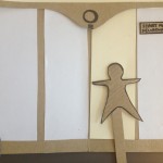
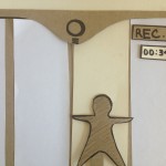
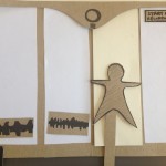
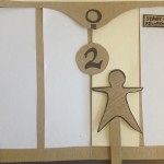
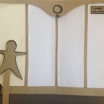
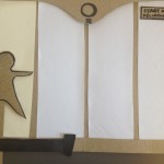
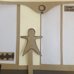
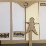
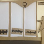
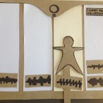
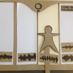
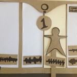
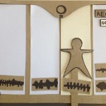
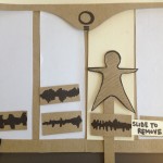
Our prototype consists of a paper screen (which would be the projector/TV). The user data (taken by the kinect) is shown as a paper puppet which can be moved around from panel to panel. Each panel represents a horizontal span of space. Users can move from between panels by moving horizontally in front of the kinect.

The following gestures manipulate the prototype:

  • Raise both hands: start/stop the master recording
  • Raise right hand: record a clip which will be saved in the panel that the user is standing in
  • Move side-to-side: switch between panels in the direction of movement
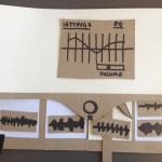
  • Both arms drag down: bring down settings screen
  • Both arms drag up: close the settings screen up
  • Touch elbow and drag horizontally: remove a sound clip on screen.

3. 3 TASKS

Task #1: Recording a simple master track.

This task is similar to hitting “record” on a traditional recording application — it just records one sound clip. The following video shows how the user would interact with the prototype:

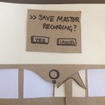
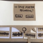
The user raises both arms to start the recording. The user then sings the song into a microphone or directly to some sound-recording device. To finish recording, the user raises both arms again. Then a menu drops down which asks if the user wishes to save their recording. The user would indicate with their arm the choice to save or cancel the recording.

This task worked well with our paper prototype we built.

Task #2: Recording multiple clips and overlaying them.

This task involves the user moving between panels and recording clips of a specified length (ex. 16 beats). The bar on the bottom of the screen will indicate the user how much time they have left in the sound clip. After the clip is recorded in one panel, it will repeatedly play. The user can record multiple clips in each panel. All the clips will be playing at the same time.

The user raises their right arm to start the recording in one panel. The user then sings the song into a microphone or directly to some sound-recording device. The bar at the bottom of the screen shows how much time is left in the sound clip (ex. 16 beats total, 5 beats left). When time runs out, recording stops and a track appears in the panel. To switch between screens, the user moves horizontally into another panel. All the recorded clips are being played back repeatedly at the same time.

This task was hard to show because in our final project, once a sound clip is recorded it will continually loop and play back. When users add additional sound clips, they will simultaneously play back. This was hard to show because we had no sound playback in our paper prototype!

One issue we realized we had to consider after making this prototype is how to sync recording for each individual sound clip. We may have to add a countdown similar to the master recording, but for each sound clip.

Task #3: Recording multiple clips and combining them into one master recording.

The user may have no clips or some clips already recorded in each panel. The user starts recording the master track and all the clips on screen (currently repeating together). The user can also add more clips into the panel they are standing in. The user can remove clips from the panel they are standing in. Settings can also be adjusted by bringing down the menu and changing EQ and overall recording volume.

User raises both arms to start master recording. User can now move between panels and record individual clips (adding extra clips to the sound) like in Task #2. Point arm to elbow and drag horizontally outwards to remove the sound clip in current panel. User can also use both arms, dragging down, to pull down the settings menu. When users are finished they can drag both arms up to close the settings menu.

Similar difficulties as in task #2.

4. DISCUSSION

We made our prototype with paper, glue, cardboard, and markers. Since our system is gesture based, we also made little paper puppets to simulate usage in a more streamlined way than jumping around ourselves and panning a camera back and forth. The only real difficulty we encountered was determining precisely how to realize our conceptual ideas about the software, especially because paper does not express screen position (of the person) like we would like the kinect to do. To fix this, we created a little “puppet” which represented the user’s position on the screen. We think we were moderately successful at capturing the user-screen interaction, however in the future we would like to reflect gestures on screen to better teach users how to use our interface.

The main thing which the paper prototype could not show was the audio feedback, since the sound clips would be playing repeat after the user records it. In this way, paper prototyping was not good at giving an accurate representation of the overall feel of our system. However, it was paper prototyping was good at forcing us to simplify and streamline our interface and figure out the best gestures to interact with it. Paper prototyping forced us to answer the following questions precisely: what should and should not be on the screen? Should we prototype every single little scenario or just a representative cross-section? For which functions should we switch to mouse control?  We ended up prototyping representative actions and did not show some of the settings (such as beat count, represented by the bar on the bottom of the screen) which we assumed in the current prototype would already be set. Showing the separate screens for each standing position of the user worked really well. The status for recording the master track could be more visible (by having the screen turning a different color, for example), so we would improve on this in the future.

P3 – BackTracker

Group #7, Team Colonial Club

David Lackey (dlackey), John O’Neill (jconeill), and Horia Radoi (hradoi)

Mission Statement

We are evaluating a system that makes users aware of bad posture during extended hours of sitting.

Many people are bound to sedentary lifestyles because of academics, desk jobs, etc.  If people have bad posture during the hours that they are seated, then it can lead to back problems later in life, such as degenerative disc disease.  We want our system to quickly alert people in the event that they have bad back posture so that they can avoid its associated negative long term effects.

From our first evaluation of our low-fidelity prototype, we hope to gain insight into what it will take to make a wearable back posture sensor.  We also want to learn how to correctly display relevant back posture information / statistics to the user.  Figuring out how to alert the user is important as well.

Concise Mission Statement

It is our mission to help users recognize when they have bad posture while sitting so that they can avoid long term back problems.

Team Roles

David – Drafted mission statement.
John – Initiated construction / task evaluations.
Horia – Formatting.

Description of Prototype

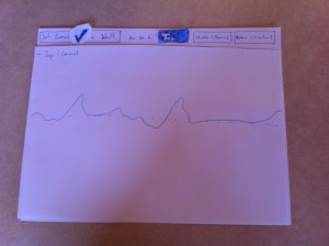
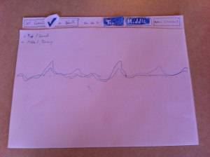
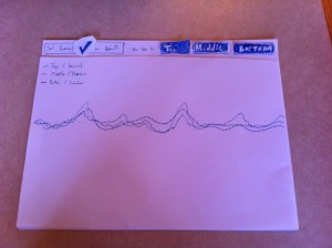
Our prototype consists of two components: the wearable device and the desktop interface. The first is intended to replicate how the user engages with the wearable component, and, as a prototype, demonstrate how vibrations are delivered to points on the users back where they are deviating from their desired posture. The second component serves two purposes: 1.  to demonstrate how the user sets their desired / default posture, and 2. to display to the user how the specific areas of their back deviate from their desired position over time.

image

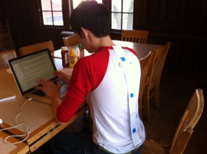
User is working at table with device attached. Note that there are there sensors, each one designating a specific portion of the spine.

image_1

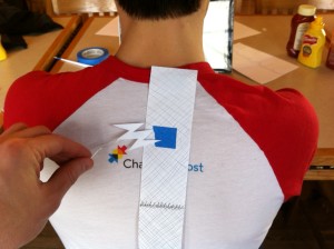
Here we demonstrate a vibration given by the device. We represent the location of vibrating motors with the placement of blue tape.

image_2

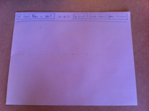
Base interface before readings have been taken / default has been set.

image_3

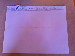
Once user sets default / desired posture, a confirmation check is placed on the screen for validation.

image_4

The user chooses to display the information provided by the top set of sensors.

image_5

The user chooses to also display the data received from the middle set of sensors. This data is laid over the other set of data that has previously been selected.

image_6

The user has selected to show all three sets of data.

Task Descriptions

Task #1: Set up a desired back position (medium)

For this task, the user is placing the device on their back and is designating their desired back position. Doing so enables the user to use the remaining features, and allows the user to customize the “base” posture that they wish to abide by.

[kaltura-widget uiconfid=”1727958″ entryid=”0_q2ik6xwp” width=”400″ height=”360″ addpermission=”” editpermission=”” /]

Task #2: Alert user if back posi­tion / pos­ture devi­ates too far from desired posture (easy)

For this task, the user is alerted if they deviate from the posture they originally wished to maintain. This helps the user become conscious of – and thus, adjust – any areas of their back that may be receiving excessive stress. The user is notified by the vibration of a motor near the area(s) of concern.

[kaltura-widget uiconfid=”1727958″ entryid=”0_s475xnr3″ width=”400″ height=”360″ addpermission=”” editpermission=”” /]

Task #3: Mon­i­tor how their pos­ture changes. (hard)

[kaltura-widget uiconfid=”1727958″ entryid=”0_1of32m3f” width=”400″ height=”360″ addpermission=”” editpermission=”” /]

Prototype Discussion

1. We created both components using paper and tape, using pen to designated different forms of information – data over time, buttons, and our mesh resistors.

2.  We agreed that a mock paper wearable device, as well as as a mock paper computer interface, were an appropriate step before creating a sensor-rich, coded version.

3. One thing that was difficult was determined how we wished to represent the deviance data over time. We decided that the best was to have a baseline: then, as a sensor bent one way, it traveled above this baseline – conversely, as it bent the other way, the plot line traveled below.

4. One thing that worked well was using different versions of the graph on different sheets of paper. This allowed us to easily show how user actions (specifically, selected buttons) would effect changes in the graph.

P3

Team TFCS: Dale Markowitz, Collin Stedman, Raymond Zhong, Farhan Abrol

Mission Statement

In the last few years, microcontrollers finally became small, cheap, and power-efficient enough to show up everywhere in our daily lives — but while many special-purpose devices use microcontrollers, there are few general-purpose applications. Having general-purpose microcontrollers in things around us would be a big step towards making ubiquity of computing and would vastly improve our ability to monitor, track, and respond to changes in our environments. To make this happen, we are creating a way for anyone to attach Bluetooth-enabled sensors to arbitrary objects around them, which track when and for how long objects are used. Sensors will connect to a phone, where logged data will be used to provide analytics and reminders for users. This will help individuals maintain habits and schedules, and allow objects to provide immediate or delayed feedback when they are used or left alone.

Because our sensors will be simple, a significant part of the project will be creating an intuitive interface for users to manage the behavior of objects, e.g. how often to remind the user when they have been left unused. To do this, Dale and Raymond designed the user interface of the application, including the interaction flow and screens, and described the actual interactions in the writeup. Collin and Farhan designed, built, and documented a set of prototype sensor integrations and use cases, based on the parts that we ordered.

Document Prototype

We made a relatively detailed paper prototype of our iOS app in order to hash out what components need to go in the user interface (and not necessarily how they will be sized, or arranged, which will change) as well as what specific interactions could be used in the UI. We envision that many iOS apps could use this sensor platform provided that it was opened up; this one will be called Taskly.

Taskly Interface Walkthrough

Taskly Reminder App

Below, we have a created a flowchart of how our app is meant to be used. (Right-click and open it in a new tab to zoom.)

Here we have documented the use of each screen:

IMG_0630

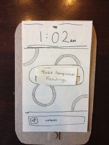
When a user completes a task, it is automatically detected by our sensor tags and pushes the user an iPhone notification–task completed!


IMG_0617

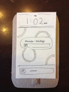
User gets a reminder–time to do reading!

IMG_0618

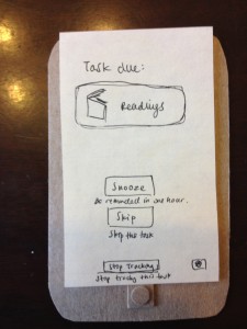
More information about the scheduled task–user can snooze task, skip task, or stop tracking.

IMG_0619

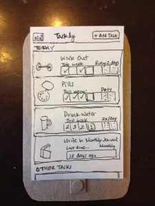
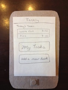
Taskly start screen–user can see today’s tasks, all tracked tasks, or add a new task

IMG_0620

When user clicks on “MyTasks”, this screen appears, showing weekly progress, next scheduled task, and frequency of task.

IMG_0621

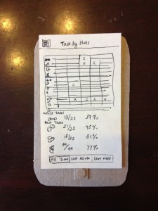
When user clicks on the stats icon from the My Tasks screen, they see this screen, which displays progress on all tasks. It also shows percent of assigned tasks completed.

IMG_0622

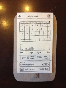
User can also see information about individual scheduled tasks, like previously assigned tasks (and if they were completed), a bar chart of progress, percent success at completing tasks, reminder/alert schedules, etc. User can also edit task.

IMG_0623

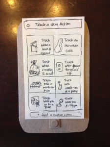
When user clicks, “Track a New Action”, they are brought to this screen, offering preset tasks (track practicing an instrument, track reading a book, track going to the gym, etc), as well as “Add a custom action”

IMG_0627

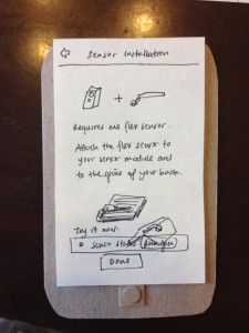
User has selected “Track reading a book”. Sensor installation information is displayed.


IMG_0629

IMG_0625

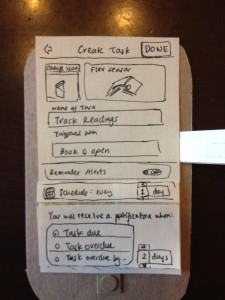
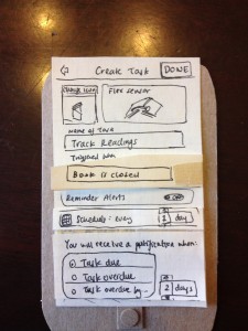
User can name a task here, upload a task icon, set reminders, change sensor notification options (i.e. log when book is opened) etc.

IMG_0624

Here, user changes to log task when book is closed rather than opened.

IMG_0628

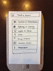
When a user decides to create a custom task, they are brought to the “Track a Sensor” screen, which gives simple options like “track light or dark”, “track by location”, “track by motion”, etc.

IMG_0626

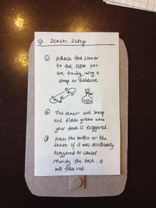
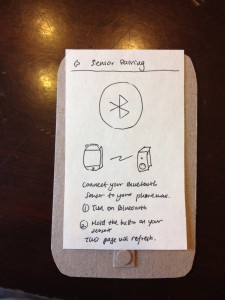
Bluetooth sensor setup information

Document Tasks

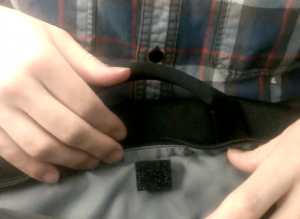
Easy: Our easy task was tracking how often users go to the gym. Users put a sensor tag in their gym bags, and then our app logs whenever the gym bag moves, causing the sensor tag’s accelerometer to note a period of nonmovement followed by movement. We simulated this with our fake tags made out of LED timer displays (about the same size, shape of our real sensors). We attached the tags to the inside of a bag.

Our app will communicate with the tag via Bluetooth and log whenever the tag’s accelerometer experiences a period of nonmovement followed by movement (we’ve picked up the bag!), nommovement (put the bag down at the gym), movement (leaving the gym), and nonmovement (bag is back at home). It will use predefined thresholds (a gym visit is not likely to exceed two hours, etc.) to determine when the user is actually visiting the gym, with the visit starting when the bag remains in motion for awhile. To provide reminders, the user will configure our app with the number of days in a week they would like to complete this task, and our app will send them reminders via push notification if they are not on schedule, e.g. if they miss a day, at a time of day that they specify.

Accelerometer Sensor for Gym Bags

Screen shot 2013-03-29 at 10.38.35 PM

Sensor is placed in a secure location in a gym bag, Its accelerometer detects when the bag is moved.

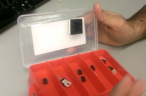
Medium: Our medium difficulty task was to log when users take pills. We assume that the user’s pillbox is typically shaped, i.e. a box with a flip-out lid and different compartments for pills (often labeled M, T, W, etc.). This was exactly the same shape as our Sparkfun lab kit, so we used it and had integrated circuits represent the pills. We attached one of our fake tags (LED timer display) to the inside of the box lid.

Our app connects to the tag via bluetooth and detects every time the lid is opened, corresponding to a distinct change of about 2 g’s in the accelerometer data from our tags. To provide reminders, the user sets a schedule of times in the week when they should be using medication. If they are late by a set amount of time, or if they open the pillbox at a different time, we will send them a push or email notification.

Magnetometer Sensor for Pill Containers

Screen shot 2013-03-29 at 10.40.00 PM

This “pillbox” is structurally very similar to the pillbox we imagine users using our product with (we even have IC pills!). A sensor is placed on the inside cover, and its accelerometer detects when the lid has been lifted.

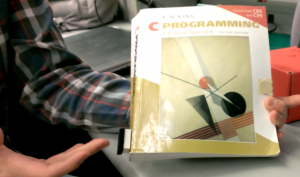
Hard: Our hard task was to track how frequently, and for how long, users read tagged books. Users will put a sensor on the spine of the book they wish to track. They will then put a thin piece of metal on the inside of the back cover of the book. Using a magnetometer, the sensor will track the orientation of the back cover in reference to the book’s spine. In other words, it will detect when the book is opened. Our iPhone app will connect to the sensor via bluetooth and record which books are read and for how long. It is important to note that this system is most viable for textbooks or other large books because of the size of the sensor which must attach to the book’s spine. Smaller books can also be tracked if the sensor is attached to the front cover, but our group decided that such sensor placement would be too distracting and obtrusive to be desirable.

This is the most difficult hardware integration, since sensors and magnets must fit neatly in the book. (It might be possible for our group to add a flex sensor to the microcontroller which underlies the sensors we purchased, thus removing the issue of clunky hardware integration in the case of small books. In that case, neatly attaching new sensors to the preexisting circuit would likely be one of the hardest technical challenges of this project.)

To track how often books are read, the user will set a threshold of time for how long the book can go unused. When that time is exceeded, our app will send them reminders by push notification or email. The interface to create this schedule must exist in parallel to interfaces for times-per-week or window-of-action schedules mentioned above.

Magnetometer Sensor for Books

Screen shot 2013-03-29 at 10.37.26 PM

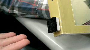
User attaches sensor to spine of a book. The magnetometer of the sensor detects when the magnet, on the cover of the book, is brought near it.

Screen shot 2013-03-29 at 10.37.42 PM

Sensor on spine of book.

Our Prototypes

How did you make it?:

For our iPhone app, we made an extensive paper/cardboard prototype with 12 different screens and ‘interactive’ buttons. We drew all of the screens by hand, and occassionally had folding paper flaps that represented selecting different options. We cut out a paper iphone to represent the phone itself.

For our sensors, we used an LED seven-segment display, as this component was approximately the correct size/shape of the actual sensor tags we’ll be using. To represent our pillbox, we used a sparkfun box that had approximately the same shape as the actual pillboxes we envision using our tags with.

Did you come up with new prototyping techniques?:

Since our app will depend upon sensors which users embed in the world around them, we decided that it was important to have prototype sensors which were more substantial than pieces of paper. We took a seven-segment display from our lab kit and used that as our model sensor because of its small box shape. Paper sensors would give an incorrect sense of the weight and dimensions of our real sensors; it is important for users to get a sense for how obtrusive or unobtrusive the sensors really are.

What was difficult?

Designing our iPhone app GUI was more difficult than we had imagined. To “add a new task,” users have to choose a sensor and ‘program’ it to log their tasks. It was difficult for us to figure out how we could make this as simple as possible for users. We ultimately decided on creating preset tasks to track and what we consider to be an easy-to-use sensor setup workflow with lots of pictures of how the sensors worked. We also simplified the ways our sensors could work. For example, we made sensor data discrete. Instead of our accelerometers to track acceleration, we allow users to track movement or no movement.

What worked well?

Paper prototyping our iPhone app worked really well because it allowed us, the developers, to really think through what screens users need to see to most easily interact with our app. It forced us to figure out how to simplify what could have been a complicated app user interface. Simplicity is particularly important in our case, as the screen of an iPhone is too small to handle unnecessarily feature-heavy GUIs.

Using a large electronic component to represent our sensors also worked well because it gave us a good sense of the kinds of concerns users would have when embedding sensors in the objects and devices around them. We started to think about ways in which to handle the relatively large size and weight of our sensors.