L2- TFCS

Dale, Colin, Farhan, Raymond – 4

We decided to build a Glove that controls the pitch of a song as it is being played. It was a real time interactive control on the music which allowed the user to create dubstep like effects on the music stream. The final system implemented the desired control well and mapped the up and down gestures to the pitch of the music. One improvement could be a more continuous mapping to the pitch, instead of the up and down motion corresponding to step shifts in the pitch, we could have a more fine control using the movements of the hand. We would also like to add gestures for controlling the wobble effect on the music (a left right twist of the wrist or such).


Instrument 1 – Scream Box (aka The Egg from Harry Potter):

The first instrument we designed was a box that starts making high pitched noise when you open it. As you try to cover the top with your hands, the pitch of the sounds goes down and to shut it off you close the lid of the box. The aim was to make a system that is a standalone musical object that has a very real-world mapping to it – you try to cover  as much of the box to make it quieter. The device uses a photo-sensor to measure how covered the top of the box is.

Instrument 2 – Touch Sensing Piano:

The aim was to recreate a piano like instrument with capacitive sensing aluminium foils as the keys. The mapping to create sound is natural, and the use of capacitive sensing makes the interaction feel natural and unobstructed.

Instrument 3 – Pitch Controlling Glove:

This instrument tries to map physical gestures to pitch control on music. The device uses an accelerometer to recognize motions of the hand and maps them to controlling the up of down pitch of a song. This can be used to recreate the “dubstep” effect on songs.


Final Instrument: Pitch Glove

We decided to refine the pitch glove because it afforded a very novel kind of interaction with the music and allowed control over a parameter of the music with gestures. The refining process was mainly dealing with mapping the accelerometer data to correct gestures and making the piping to the pitch control software work.

Parts List:

  1. Arduino Uno
  2. Processing Software

Instructions:

  1. Download the code for the processing of the music.
  2. Attach the Arduino either to your wrist using a strap, or hold it in your hand.
  3. Enjoy the music move with your gestures.

Code:
Arduino Controller

const int groundpin = A2; // analog input pin 2
const int powerpin = A0; // analog input pin 0
const int xpin = A5; // x-axis of the accelerometer
const int ypin = A4; // y-axis
const int zpin= A3; // z-axis
void setup()
{
//initialize the serial communications:
Serial.begin(9600);
// Provide ground and power by using the analog inputs as normal
//digital pins. This makes it possible to directly connect the
//breakout board to the Arduino. If you use the normal 5V and
//GND pins on the Arduino, you can remove these lines.
pinMode(groundpin, OUTPUT);
pinMode(powerpin, OUTPUT);
digitalWrite(groundpin, LOW);
digitalWrite(powerpin, HIGH);
}
void loop()
{

if(analogRead(zpin) > 440)
{
  Serial.print("h");
}
else if(analogRead(zpin) < 280)
{
  Serial.print("l");
}
else
{
  Serial.print("n");
}

}

Music Controller

// Parts of this code were based on Sampling_03.pde from Sonifying Processing tutorial

import beads.*;
import processing.serial.*;
AudioContext ac;
SamplePlayer sp1;
Gain g;
Glide gainValue;
Glide rateValue;
Glide pitchValue;
Serial myPort;
float rate;
float pitch;
char serialVal;
int bufferSize = 0;

void setup()
{
  String portName = Serial.list()[0];
  myPort = new Serial(this, portName, 9600);

  size(512, 512);
  background(0); // set the background to black
  stroke(100);
  line(width/2, 0, width/2, height);
  line(3*width/4, 0, 3*width/4, height);
  line(0, height/2, width, height/2);
  text("", 100, 120);

  ac = new AudioContext();
  try {  
    sp1 = new SamplePlayer(ac, new Sample(sketchPath("") + "music.mp3"));
   }
  catch(Exception e)
  {
    println("Exception while attempting to load sample!");
    e.printStackTrace();
    exit();
  }

  sp1.setKillOnEnd(false); // we want to play the sample multiple times

  pitchValue = new Glide(ac, 1, 30);
  sp1.setPitch(pitchValue);

  rateValue = new Glide(ac, 1, 30);
  sp1.setRate(rateValue);

  gainValue = new Glide(ac, 1, 30);
  g = new Gain(ac, 1, gainValue);
  g.addInput(sp1);
  ac.out.addInput(g);

  ac.start();  
}

void draw() {

  //read value from serial port.
  if ( myPort.available() > 0) {  // If data is available,
    serialVal = myPort.readChar();         // read it and store it in val
    bufferSize++;
  }

 if(bufferSize > 10)
 {
   myPort.clear();
   bufferSize = 0;
 }
 float dRateValue;
 if(serialVal == 'h')
 {
   dRateValue = 0.01;
 }
 else if(serialVal == 'l')
 {
   dRateValue = -0.01;
 }
 else
 {
   dRateValue = 0;
 }

  println(serialVal);
  // calculate the mouse position on screen as displacement from center, with a threshold
  // TODO: feed in the accelerometer values here
  //float dRateValue = ((float)mouseX - width/2.0);
  //float dPitchValue = ((float)mouseY - height/2.0);

  //if (abs(dRateValue) < 10) dRateValue = 0;
  //if (abs(dPitchValue) < 10) dPitchValue = 0;
  /*
  if(serialVal == 10)
  {
    dPitchValue = 0;
  }*/

  // adjust the rate and pitch depending on the X and Y position of the mouse, drawing a trace
  stroke(100);
  point(rate*width/10.0 + width/2.0, pitch*height/10.0 + height/2.0);
  rate += dRateValue;
 // rate = 2*dRateValue/width;
 // pitch = dPitchValue/height/10;
  stroke(255);
  point(rate*width/10.0 + width/2.0, pitch*height/10.0 + height/2.0);

  // print and set output
  println("Rate: " + rate + "; Pitch: " + pitch);
  rateValue.setValue(4.0*rate);
  pitchValue.setValue(-2.0*pitch + 1.0);
  sp1.setPitch(pitchValue);
  sp1.setRate(rateValue);

  delay(10);
}

void mousePressed() {
  rate = 0;
  pitch = 0;
}


A2 Free Food Finder

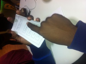
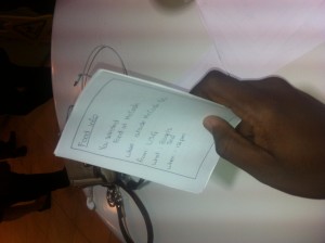
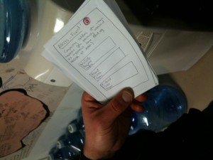
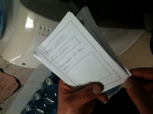
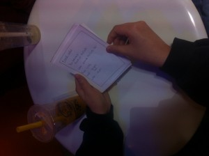
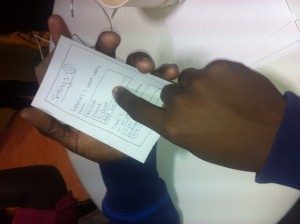
Lauren Berdick I paper prototyped an app that uses the freefood listerv in order to display and give information about where to find free food on campus.

Observations:

I observed people in-between lectures. People entertain themselves with an eclectic mixture of habits. Some people munch on food, either snacks or two course meals they got from late meal. Others, most likely those who have not been tired out for the week already, start to flip through a textbook, or lecture slides of the class to come. Many immediately take out their computer and start facebooking, playing random games, checking their Princeton gmail. The teachers, if they get there early, are generally setting up their computer for use with the projector, making sure their slides are organised. Some who arrive quite early may strike up a chat with a nearby student, or perhaps one of their TAs. I observed and then interviewed the following people directly to find out what they generally do, and some things they might feel would broaden their experience in these few minutes.


Nicole Loncke

She has one class before which she has a 10 minute break. They are both in McCosh, so she isn’t running frantically. She usually chats with some people if she sees anybody she knows. She’ll walk over slowly, get a good spot and then sit around. It is a music class, so the professor has music playing before class. She may talk to the person next to her if she knows them. Or, she may grab a snack. If she has a little more time, she will go to late meal. Alternatively, she will call her parents or a friend she hasn’t talked to in a while. If there are comfy chairs, she’ll take a nap, but at least 20 minutes are needed.


Daniel Brooker and Kaleb Bradford

Dan usually checks his email, because he is perpetually forgetting about things, events, etc. Kaleb calls relatives, friends to chat. He also checks facebook, emails. He may go over material for class that he is about to go to, but generally only if there is a quiz. Both also wanted to take naps. Dan likes music, so he would go for something in entertainment, music related, maybe play some game. Kaleb and Dan are sports fans, so they would check sports news, team scores. Kaleb would prefer to be able to follow specific teams. Dan feels he would want to check news, current events, etc, because he thinks Princeton students seem isolated from the daily goings on. They would prefer not to work during that small break, because they already spend most of their time outside class working, and then of course the time for the class lectures, precepts, labs. They don’t want to do more work during those 10 minutes. They need a break.


Brainstorm:

  • FreeFoodFinder: app to find food using the freefood listserv. Find food near you!
  • CallMe! : app that gives you an alert of who you haven’t called recently (but you have the ability to ignore that alert if you want)
  • OrganiseMe! : integrated with google calendar. Tells you what assignments you should start working on
  • Reminderapp: tells you what assignments you haven’t worked on for a while. “Why don’t you do a questions from this problem set?”
  •  Sleepify: app to show you where comfy places are to sleep/sit. (possible name) “Nooks and Crannies”
  • app integrated with blackboard, so has practice quizzes. Gives you a practice quiz question
  • Or practice LSAT, MCAT  question a day, or when you open app
  • FunnyBone: app that you can enter funny moments with your friends and so when you are bored, open the app and say, “Show me a funny moment in my past”, and then it will pull up a random memory
  • Scan emails for keywords, make a calendar out of it, and then you can check it what’s coming up
  • NapTaker, say I want to nap now, wakes you up 10 mins later.
  • Nap schedule, shows graphic of when can you take a nap
  • Filters for news, so you can be alerted of those kind of things in that area of news
  • Name game. Get to know your neighbours
  • A collaborative art project, maybe facebook photos that people contribute to
  • One tough problem that everyone contributes to

I chose free food because I had been wanting to do something like this for a while. Also, it may be a stereotype, but I hear Princeton students love free anything, especially food. This is what I got user feedback on. I also chose the CallMe app, because it seems like a lot of students like to call people they have not spoken to in a while during that break time.

Prototype: 

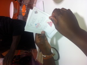
App loading and title page

FreeFoodFinder – app that finds free food on campus for you, using the freefood listserv

In the field:

Ajibike looking at loading page


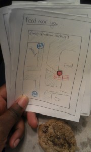
Nicole looking at the Food Neat You! screen. Screen showing your current location as a red dot and food locations as blue dots. Food near you shows food locations in a certain radius surrounding your location.


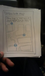
Screen which shows all food choices on campus, regardless of your location.

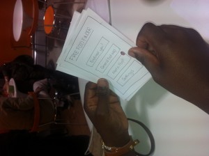
Screen showing menu options for users. The buttons lead to the following screens.


Kwaku, another user, deciding to look for free food

Kwaku selecting Food for You! This will bring him to the map page showing his current location and free food spots within a certain radius


Screen giving specific details on food: where, when, what. One way to get here is to select one of the blue food dots on the map.


Greg looking at the AlertMe! screen. This alerts you when there is food in certain locations (locations that the user previously set as a Favourite).

Greg selecting a location to find food in.


April checking out what her free food will be


Settings page — where the user can set preferences, e.g. “Favourite” locations that the user wants alerts from


Feedback

Ajibike Lapite

  • –wants background music
  • –“I like it”
  • –would definitely use it


Kwaku Ohemeng

  • –is there a way of making availability of food in real time?
  • –How much food is left?
  • –in settings, be able to change colour. Personalise app
  • –Main concern: Can we reserve food? If we ran and not there anymore would be a waste of time
  • –but it is cool
  • –would use it
  • –wants extra features available to independent students
  • –because they might be most likely to use this


April Liang

  • –What is the time? Because most free food emails say “food right now!” So would have to use email timestamp instead of finding time in email
  • –Select location should include a radius set by user
  • –Yes would use it


Greg Owen

  • –Might use, but probably not every day
  • –Would be great app if I had more time, like 30 mins in between class, because might have to go out of my way
  • –Definitely use Alert Me at a given time feature, because I know regularly when I am craving some food

Team X – Lab 2

Group 10:

  • Osman Khwaja (okhwaja)
  •  (av)
  • Igor Zabukovec (iz)
  • Junjun Chen (junjunc)

Prototype 1: The Buzz Drum

The piezo element picks up knocks (of varying loudness), causing the buzzer to buzz.

This prototype uses the Piezo sensor and a buzzer. When the piezo sensor senses a vibration, like when we knock on the surface, it sends a signal to the Arduino which then causes the buzzer to buzz. So, essentially, when you drum it, it buzzes.


Prototype 2: The Flex Buzz

The flex sensor changes the frequency of the buzzer tone.

This prototype uses the buzzer and the flex sensor. When the sensor is flexed, the tone of the buzzer was changed. In theory, it sounded like a good idea. In reality, we didn’t have much control over the flex sensor’s output values and the change in the buzzer was not as apparent as we had hoped.

Final Prototype/Prototype 3: DJ Breadboard

Our last prototype uses a potentiometer, accelerometer, and a button all located on the breadboard to control the output sound from the computer.

We thought this would be really cool because, using a couple of sensors, we could control many different aspects of the sound. The potentiometer controls frequency of the synthesized sound (just a triangle wave and a sine wave together). The x and y axis of the accelerometer control the left-right panning of the triangle and sine wave, respectively.  Lastly, the button fades the sound in or out. We used Arduino and Processing’s Sound Module (Minim)
Final System Parts:

  1. Arduino + USB cord + Breadboard
  2. Wires
  3. 1 10 kohm resistor
  4. 1 ADXL335 accelerometer
  5. 1 Button
  6. 1 Rotary Potentiometer

Instructions:

Connect the accelerometer to the Arduino (Vin to A0, 3Vo to A1, Gnd to A2, Yout to A4, Xout to A5). Note that we don’t connect Zout to the Arduino, as we won’t be using the Z axis, and we need A3 for the rotary pot. Connect the button to digital pin 2 (as well as 5V and the 10kohm resistor to ground).  Connect the rotary pot to A3 (and 5V and ground). Run the following code in Arduino and Processing

Arduino Code:

// these constants describe the pins. They won’t change:

const int groundpin = A2; // analog input pin 2

const int powerpin = A0; // analog input pin 0

const int xpin = A5; // x-axis of the accelerometer

const int ypin = A4; // y-axis

// const int zpin = A3; // z-axis

const int pot = A3;

const int button = 2;

void setup()

{

// initialize the serial communications:

Serial.begin(9600);

// Provide ground and power by using the analog inputs as normal

// digital pins. This makes it possible to directly connect the

// breakout board to the Arduino. If you use the normal 5V and

// GND pins on the Arduino, you can remove these lines.

pinMode(groundpin, OUTPUT);

pinMode(powerpin, OUTPUT);

pinMode(button, INPUT);

pinMode(pot, INPUT);

digitalWrite(groundpin, LOW);

digitalWrite(powerpin, HIGH);
establishContact();

}

void loop()

{
if (Serial.available() > 0) {
// print the sensor values:
double b = (digitalRead(button) == HIGH) ? 1 : 0;

double a = analogRead(pot) / 1023.0;

double x = (343.0 – analogRead(xpin)) / (413.0 – 343.0);

double y = (341.0 – analogRead(ypin)) / (411.0 – 341.0);
Serial.print(x);

// print a tab between values:

Serial.print(“,”);

Serial.print(y);

Serial.print(“,”);

Serial.print(b);

Serial.print(“,”);

Serial.println(a);

}
}

// Establish contact with processing.
void establishContact() {
// Send an initial string until connection made
while (Serial.available() <= 0) {
Serial.println(“0,0,0”);
delay(300);
}
}

Processing Code:

import ddf.minim.*;
import ddf.minim.signals.*;
import controlP5.*;
import processing.serial.* ;

Serial port;

Minim minim;
AudioOutput out;
SineWave sine;
TriangleWave tri;
ControlP5 gui;

public float triAmp = 0.5;
public float triPan = 0;
public float triFreq = 880;

public float sinAmp = 0.5;
public float sinPan = 0.5;
public float sinFreq = 440;

void setup()
{
size(512, 400, P3D);
minim = new Minim(this);
// get a stereo line out from Minim with a 2048 sample buffer, default sample rate is 44100, bit depth is 16
out = minim.getLineOut(Minim.STEREO, 2048);
// create a sine wave Oscillator, set to 440 Hz, at 0.5 amplitude, sample rate 44100 to match the line out
sine = new SineWave(440, 0.5, out.sampleRate());
// set the portamento speed on the oscillator to 200 milliseconds
sine.portamento(200);
// add the oscillator to the line out
out.addSignal(sine);
// create a triangle wave Oscillator
tri = new TriangleWave(880, 0.5, out.sampleRate());
tri.portamento(200);
out.addSignal(tri);

// set up the gui
gui = new ControlP5(this);
gui.addKnob(“triFreq”, 40, 5000, 10, 250, 60);
gui.addKnob(“triAmp”, 0, 1, 0.5, 85, 250, 60);
gui.addKnob(“triPan”, -1, 1, 0, 165, 250, 60);
gui.addKnob(“sinFreq”, 40, 5000, 280, 250, 60);
gui.addKnob(“sinAmp”, 0, 1, 0.5, 355, 250, 60);
gui.addKnob(“sinPan”, -1, 1, 0, 430, 250, 60);

/* Get serial data. */
println(“Available serial ports:”);
println(Serial.list());

port = new Serial(this, Serial.list()[0], 9600);

port.bufferUntil(‘\n’); /* Read in one line at a time. */
delay(1000);

}

void draw()
{
background(0);
gui.draw();
stroke(255);
// draw the waveforms

}

void stop()
{
out.close();
minim.stop();

super.stop();
}

void serialEvent(Serial port) {

String myString = port.readStringUntil(‘\n’); /* Read in a line. */
myString = trim(myString); /* Remove leading / tailing whitespace. */
float sensors[] = float(split(myString, ‘,’));

if (sensors.length == 4) {
tri.setFreq(sensors[3] * 1000);
tri.setAmp(triAmp);
tri.setPan(sensors[0]);
sine.setFreq(sensors[3] * 1000);
sine.setAmp(sinAmp);
sine.setPan(sensors[1]);

if (sensors[2] < 0.5) { tri.setAmp(0); sine.setAmp(0); } if (sensors[2] > 0.5) {
tri.setAmp(1);
sine.setAmp(1);
}

// Print out sensor values:
for (int sensorNum = 0; sensorNum < sensors.length; sensorNum++) {
print(“Sensor ” + sensorNum + “: ” + sensors[sensorNum] + “\t”);
}
println();
}

port.write(“A”); // Send byte to get more data from Arduino program.
}

Lab 2 – Team Cake

Members: Connie, Angie, Kiran, Edward
Lab Group 13

We built two sets of hardware interfaces: our final instrument was a wind instrument that played chords when you blew into “pipes” (straws), and our alternate interface was a “force-sensitive softpot” that combined the two sensors into a single control element. In our final instrument, we blew on a thermistor to change its temperature and combined three of these to create a wind-like instrument. We liked the weirdness of using heat to play music, as well as the quirky design: we used straws as the blowholes on our Arduino. The simple but exotic interface also lent itself well to our eerie synthesis mappings. However, it would have been better if we could have had a larger array of thermistors. Then, instead of mapping each thermistor change to a scale of notes, we could have done more complicated things and given the user more control. All in all, we were very satisfied with the sounds created by our final instrument – the ambiance that it gave off was really cool, and we thought it went really well together with our wind instrument interface.

Force-sensitive Softpot Instrument

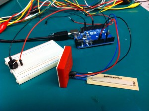
For our first two instruments, we used the same hardware interface. We wanted to design an instrument that deeply combined two sensors to create a different experience than we made in previous labs, where all the sensors were separate in the interface. Thus, we decided to make a Force-sensitive Softpot, that sensed not only where on a slider you were touching but also how hard. Combining the two dimensions of input like this made controlling two parameters into one action, allowing for more artistic effects.

We created two different mappings for our FSS instrument. The first was very simple, where position along the softpot mapped directly to frequency and the force on the FSR mapped to volume. Our choice of waveform (sine wave with a slight reverb) this created an eerie-sounding howling effect. We found after some experimentation that the softpot required a certain minimum level of force to give stable readings, so we adapted the FSR mapping to be thresholded instead (only mapping readings above the threshold to volume).

Our second mapping was a little bit more radical. We mapped force on the FSR to timbral parameters used in waveshaping synthesis, to make a sine tone sound more “sharp” or “buzzy”. We also changed the softpot mapping to a discrete frequency mapping, so that tones were constrained to the 12 notes of the western chromatic scale. The timbral effects were especially cool – we could make sounds that almost sounded like speech, since the different levels of timbre sounded almost like different vowels, and changing between them sounded like “Wa” noises.

Final Instrument: Wind instrument


This “wind instrument” used the user’s breath to warm up thermistors placed at the bottom of the “pipes” (straws). Each pipe is responsible for a different chord and a different tempo. For example, in our demonstration we have a fast Fm6, a fast Cm9, and a slower, lower Cm9. The actual pitch classes played are randomly selected from the chord. The temperature reading controls the octave in which the chord is played: as you blow into the pipe, the chord gets higher, and as you stop blowing, the chord gradually falls down to a lower range as the thermistor cools off. This causes a fancy decaying effect, almost like the fading resonance of a struck bell.

Parts List

  • 3x Thermistor
  • 3x 330K Resistors
  • 3x Straws
  • Arduino Uno
  • Wires
  • Straws

We also require a computer installed with Processing and ChucK (and Arduino, of course).

Instructions

  1. Connect one thermistor to 5V and to A0. Connect A0 to ground through a 330K pull down resistor.
  2. Cut a straw so it is about 5cm in length. Place it on top of the thermistor
  3. Repeat steps 1 and 2 twice more for your two remaining thermistors, connecting them to A1 and A2.
  4. Loosely tape the straws together.
  5. Take some readings of the thermistor with the straws on, but without blowing into them. Set the maximum such value as the baseline in the ChucK code.
  6. To play the instrument, blow into the straws. The raised temperature of your breath should warm up the thermistors, which will gradually cool. Take off the straws if you want it to cool down faster.

Source Code

Arduino Code

/*
 Temperature Blow Straw Music Instrument
 Lab 2
 COS 436: Human-Computer Interfaces
 March 6, 2013
 Arduino Code
 */

//variables 
int temperature1; //temp sensor 1
int temperature2; //temp sensor 2 
int temperature3; //temp sensor 3

//pins
int pinT1 = A0; 
int pinT2 = A1; 
int pinT3 = A2; 

void setup()
{
  // initialize the serial communication:
  Serial.begin(9600);
}

void loop() {
  temperature1 = analogRead(pinT1);
  temperature2 = analogRead(pinT2);
  temperature3 = analogRead(pinT3);
  
  //Serial.print("Temperature 1: ");
  Serial.print(temperature1);
  Serial.print(" ");
  Serial.print(temperature2);
  Serial.print(" ");
  Serial.println(temperature3);
  
  delay(100);
}

Processing Code

/* Generic numerical message forwarding from Arduino to OSC */
import java.util.*;
import oscP5.*;
import netP5.*;
import processing.serial.*;

Serial myPort;

OscP5 oscP5;
NetAddress dest;
int port = 6448;
String oscName = "/arduinoData";

String data;

void setup() {
  size( 400, 300 );
  myPort = new Serial(this, Serial.list()[0], 9600);
  myPort.bufferUntil('\n');
  oscP5 = new OscP5(this,12000);
  dest = new NetAddress("127.0.0.1",port);
}

void serialEvent(Serial myPort) {
  String instr = myPort.readStringUntil('\n');
  data = instr;
  sendOsc();
}

void draw() {
 ;
}

void sendOsc() {
  OscMessage msg = new OscMessage(oscName);
  String[] tokens = data.split("\\s");
  for (int i = 0; i  0) {
      msg.add(Float.parseFloat(tokens[i]));  
    }
  }
  oscP5.send(msg, dest);
}

ChucK Code

// HCI Lab 2 - Wind Instrument 
// ChucK Synthesis Script
// Generates random notes in chords, with the octave based on the readings from the arduino.
JCRev r => Gain g => dac;
.1 => r.mix;
.7 => r.gain; 
.5 => g.gain;

// ---------------- Globals ---------------
32 => float baseline;   // Ambient temperature readings for thermistors

1 @=> float octave[];  // Current octave
1 @=> float in[];      // Current reading
// ----------------------------------------

// ---------------- Chords ----------------
[0, 2, 4, 7] @=> int chord1[];    // I9
[5, 7, 9, 12] @=> int chord2[];   // IV
[7, 11, 14, 17] @=> int chord3[]; // V7

[0, 2, 3, 7] @=> int chord4[];    // i9
[5, 8, 12, 14] @=> int chord5[];  // iv6
[7, 11, 14, 17] @=> int chord6[]; // V7
// ----------------------------------------


// Function that plays notes in appropriate chord
fun void playstuff(int chord[], int index, int tonic, int speed) {
    SinOsc s => r;
    .2 => s.gain;
    3 => int x;
    1 => int off;
    while (true) {
        if (in[index] >= baseline) {
            Math.round((in[index] - baseline)/2) => octave[index];
            0.5 => s.gain;
            if (Math.random2(0,1) == 0) {
                1 => off;
            } else {
                3 => off;
            }
            Std.mtof(tonic + chord[(x + off)%4] + 12*octave[index]) => s.freq;
        } else {
            0 => s.gain;
        }
        x + 3 => x;
        if (x > 3) x - 4 => x;
        speed::ms => now;
    }
}

// Initialize one thread for each thermistor
spork ~ playstuff(chord4, 0, 60, 150);
spork ~ playstuff(chord5, 1, 60, 150);
//spork ~ playstuff(chord6, 2, 60, 150);
spork ~ playstuff(chord4, 2, 48, 600);


// --------------------- OSC Processing -------------------------
OscRecv recv;
6448 => recv.port;

recv.listen();

recv.event("/arduinoData, f f f") @=> OscEvent @ oe;

while(true) {
    oe => now;
    while(oe.nextMsg()) {       
		oe.getFloat() => in[0];
        oe.getFloat() => in[1];
        oe.getFloat() => in[2];
        <<>>;
    }
}

  1. ,0.,0.
  2. ,0.,0.

HCI Lab 2 — Do you even lift?

Names
Andrew, Peter, Adam, Matt

Group Number
12

What we built

We built a “magic wand,” similar to a conductor’s baton. We attached an accelerometer to the end of the wand to detect the downbeat, which triggered playing a note. We included our potentiometer prototype to allow the conductor to control what note will be played. We believe our project achieved a fair degree of success — it was intuitive enough that Adam was able to play “Twinkle Twinkle Little Star,” the “ABC’s”, and “Baa Baa Black Sheep”” with only three minutes of practice. Originally, our prototype played notes at a constant interval with no rests, so the introduction of the wand to control the timing of the notes was a large improvement. The wand interface worked well, and there’s little we would change about it. However, the potentiometer was difficult to use to control pitch, and sometimes resulted in the wrong note being played. This is the same for any musical instrument, but a better interface may have made it easier to play.

Prototype

1 — Simple Potentiometer. We built a simple circuit to assess how easily a potentiometer could be used to control pitch (and by extension, a flex sensor, a soft potentiometer, etc.) The arduino played a note of fixed duration at a fixed time interval

2 — Light Flute. We built a cardboard housing with three LEDs inside, and two slots insert cards into. When cards were inserted, they blocked the light, changing the amount of light that fell on the photosensor, which determined the pitch.

3 — Light Flute, version 2. We weren’t happy with having the notes be fixed duration. We included a flex sensor, where the amount of flex controls the duration of the note. We also added semi-transparent cards, to allow a broader array of notes to be played.

Video

You can see Adam playing “Twinkle Twinkle Little Star”. The downbeat of the wand controls when the note is played, and the position of the potentiometer controls the pitch.

Parts List

  • Breadboard
  • Wires
  • Arduino
  • Accelerometer
  • Rotary Potentiometer
  • Buzzer
  • Cardboard
  • Tape


Instructions

  1. Roll cardboard into tube. Mount breadboard and accelerometer on end of wand. Make sure the wire is long enough to allow for a free range of motion. Connect accelerometer to arduino with wires. (see tutorial here, but plug Vin to 5V instead of A0) Reinforce with tape.
  2. Attach buzzer to arduino (see tutorial here, connect to pin 8)
  3. Attach potentiometer to arduino (see tutorial here, connect to A0)
  4. Send below code to arduino


Code

(see code here)


L2: Team Colonial — The Muuzi

Team #7
John O’Neill: jconeill@
David Lackey: dlackey@
Horia Radoi: hradoi@

Project Description

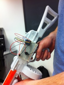
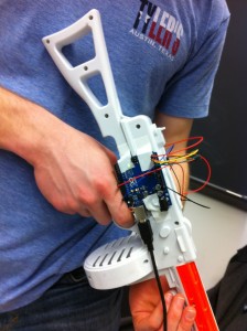
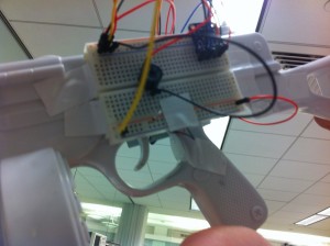
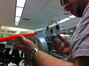
Our main project aimed to create a pointer device which enables the user to obtain a different sound based on the position of the nozzle of the gun – a musical uzi, or, as we have affectionally called it, The Muuzi. The idea came to us after we saw initial P1 brainstorm. We decided to use the accelerometer to determine the position of the gun’s x orientation, which we mapped to a range of pitches using an Arduino mapping function. The range we chose to map to was found via trial an hour; the one we settled one was the most relatively desirable, and thus, consider this version of the project to be a success. We managed to solve an issue with our intervals by performing integer division and multiplication (in order to normalize the intervals and avoid having two different noises being played at the same position.) In the future, we might expand the project to a 2- or 3-dimensional space.

Materials

  • 1 One Plastic Gun
  • 1 Accelerometer
  • 1 Arduino
  • 1 Piezo Sensor
  • 1 Breadboard

Instructions

First, place the breadboard on one side of the plastic gun and the Arduino on the opposing side. Orient and attach the accelerometer as it appears in the included photos so that any movements of the gun will correspond correctly with the provided code. Next, wire it such that the ground pin leads to A2, the power pin leads to A5, and the x-axis pin leads to A5. Now add the buzzer to pin 8, the Piezo sensor to A3, and complete the rest of the circuit as demonstrated in the accompanying photos.

Videos

gundave-480p
gunhoria-480p

Pictures

IMG_5629

The breadboard, featuring the accelerometer and the buzzer.

IMG_5628

The Arduino, attached to our musical uzi.

IMG_5635

A close-up view of the Piezo sensor, located behind the actual trigger (since the actual one generates a noise itself.)

IMG_5633

A user testing the Piezo sensor as a firing mechanism.

Source Code

const int groundpin = A2; // analog input pin 2
const int powerpin = A0; // analog input pin 0
const int xpin = A5; // x-axis 
const int xmin = 396;
const int xmax = 620;

void setup()
{
 // initialize the serial communications:
 Serial.begin(9600);

 // Provide ground and power by using the analog inputs as normal
 // digital pins. This makes it possible to directly connect the
 // breakout board to the Arduino. If you use the normal 5V and
 // GND pins on the Arduino, you can remove these lines.
 pinMode(groundpin, OUTPUT);
 pinMode(powerpin, OUTPUT);

 digitalWrite(groundpin, LOW); 
 digitalWrite(powerpin, HIGH);
}

void loop()
{
 int val = 0;
 int xreading = analogRead(xpin);
 // if the gun is pointed downward
 if ((xreading - xmin) < 20) {
   val = 0;  
 }  
 else {
   val = map(xreading, xmin, xmax, 1000, 5000);    
   val = val / 500;    
   val = val * 500;  //make values more discrete
 }    
 int x = analogRead(A3);  // read in sensor behind trigger
 if (x > 10)
   tone(8, val, 1000);
 delay(100);
}

Prototype #1: Slide Machine

This project created a music instrument in which the pitch varies according to a resistive slider. It succeeded in making the pitch vary by using a slider. It involved an led which lights up according to the power put up by the pwm. But because it was pointless, we did not include it in the final version.

slider-480p

IMG_5641

Mapping a slide sensor to different pitches. 

Prototype #2: Holy Tones

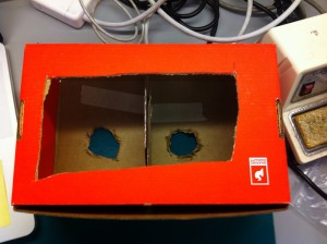
This prototype used two photocells, as well as a custom-made box which two holes, which allowed us greater control over the light that the sensors encountered. We built it as a way of developing a non-contact musical instrument, and found it moderately successful.

redbox-480p

IMG_5624

The base of our prototype, which houses two photocell sensors.

IMG_5625

The box that went over our breadboard, which had a divider to help isolate the light on each side.

L2: Bop It

Group 15: Prakhar Agarwal (pagarwal@), Gabriel Chen (gcthree@), and Colleen Carroll (cecarrol@)

Initial Prototypes:

Our first attempt at making an instrument out of a frisbee. One prong has a flex sensor underneath so the prong can be bent to control pitch.

http://www.youtube.com/watch?v=eaklr8EyHkU

Source Code: See source code for final design.

Prototype 2 uses the same base to control different elements. This time we have added a button to make the tone play only when it is pressed, as well as a rotary potentiometer for volume control.

http://www.youtube.com/watch?v=xs3a8tc6fVE

Source Code: See source code for final design.

For the last prototype, we tried something completely different, and came up with a pretty good Halloween or horror movie music maker.

http://www.youtube.com/watch?v=WSFCYuvStzk

Source Code:

/*

ADXL3xx

Reads an Analog Devices ADXL3xx accelerometer and communicates the

acceleration to the computer. For AdaFruit ADXL335 breakout board.

Modified from code at

http://www.arduino.cc/en/Tutorial/ADXL3xx

The circuit:

analog 0: Vin

analog 1: 3vo

analog 2: ground

analog 3: z-axis

analog 4: y-axis

analog 5: x-axis

test pin is hanging off the edge :)

created 2 Jul 2008

by David A. Mellis

by Tom Igoe

modified 19 Feb 2013

by Rebecca Fiebrink

This example code is in the public domain.*/

// these constants describe the pins. They won't change:

const int groundpin = A2; // analog input pin 2

const int powerpin = A0; // analog input pin 0

const int xpin = A5; // x-axis of the accelerometer

const int ypin = A4; // y-axis

const int zpin = A3; // z-axis

void setup()

{

// initialize the serial communications:

Serial.begin(9600);

// Provide ground and power by using the analog inputs as normal

// digital pins. This makes it possible to directly connect the

// breakout board to the Arduino. If you use the normal 5V and

// GND pins on the Arduino, you can remove these lines.

pinMode(groundpin, OUTPUT);

pinMode(powerpin, OUTPUT);

digitalWrite(groundpin, LOW);

digitalWrite(powerpin, HIGH);

}

void loop()

{

// print the sensor values:
Serial.print(analogRead(xpin));

// print a tab between values:

Serial.print("\t");

Serial.print(analogRead(ypin));

// print a tab between values:

Serial.print("\t");

Serial.print(analogRead(zpin));

Serial.println();

int xfreq = analogRead(xpin);
int yfreq = analogRead(ypin);
int zfreq = analogRead(zpin);

tone(8, xfreq+yfreq+zfreq);
// delay before next reading:

delay(100);

}

Description of Final Design:

Our group built a an instrument that can be played by 1-3 people. Our inspiration was essentially creating a musical Bop-It. Each end of the three-prong instrument has a different control over the sound. We liked that the instrument can be played by a range of people, our project can be the basis for a solo, duet, or trio piece. The device is limited in the range of interactions. While there are multiple useful controls, each sits on the unmoving object. With one more iteration we may have included the accelerometer to make a moving object. Additionally, we can only play within one octave because of limitations with the size of the Overall, we found the final product a fun and interesting challenge for multiple players.

In this instrument, as mentioned before, each prong of the frisbee controls a different musical aspect of the sound that the buzzer plays. One has a button to control when the tone is made. A second has a rotary potentiometer to control volume. The third will have a sliding potentiometer that determines the pitch.

http://www.youtube.com/watch?v=6ZTAg1WNUTs

Source Code:

#include "pitches.h"
/* FSR simple testing sketch.

Connect one end of FSR to power, the other end to Analog 0.

Then connect one end of a 10K resistor from Analog 0 to ground

For more information see www.ladyada.net/learn/sensors/fsr.html */

int slidePin = 0; // the FSR and 10K pulldown are connected to a0

int buttonPin = 9;

int slideReading; // the analog reading from the FSR resistor divider

int buttonReading;

void setup(void) {

// We'll send debugging information via the Serial monitor

Serial.begin(9600);

}

void loop(void) {

slideReading = analogRead(slidePin);

Serial.print("Analog reading = ");

//Serial.println(slideReading); // the raw analog reading

Serial.println(slideReading);

int freq;
if (slideReading < 125) {
freq = NOTE_C7;
}
else if (slideReading < 250) {
freq = NOTE_D7;
}
else if (slideReading < 375) {
freq = NOTE_E7;
}
else if (slideReading < 500) {
freq = NOTE_F7;
}
else if (slideReading < 625) {
freq = NOTE_G7;
}
else if (slideReading < 750) {
freq = NOTE_A7;
}
else if (slideReading < 875) {
freq = NOTE_B7;
}
else {
freq = NOTE_C8;
}
/* buzzer in 8th pin */
while (true) {
tone(8, freq);
buttonReading = digitalRead(buttonPin);
if (buttonReading == 0) {
noTone(8);
break;
}
}
}

Materials:

Three-Prong Frisbee
Buzzer
10K Resistor
Potentiometer
Button
3 Small (Red) Breadboards
1 Large Breadboard
Arduino
Electrical Tape
Wire

Instructions:

Firstly, wire the buzzer on the large breadboard and hook it up to the Arduino.
Set the button in one of the small breadboards and connect it to the buzzer so that the buzzer will now only play when the button is pressed.
In one prong, cut a hole and place the button through it. Tape it in place.
Next, set the rotary potentiometer in another small breadboard. You will wire this to the buzzer, replacing the resistor in the buzzer circuit with the rotary pot.
Cut a hole in another prong and place the rotary pot though it. Tape it in place.
Lastly, wire the sliding potentiometer on a small breadboard and attach the output to an input pin on the arduino. The code below shows how we map the potentiometer readings to buzzer frequencies.
Cut a hole in the frisbee on the last prong and slip the sliding pot through it. Tape it in place. You now have a musical bop-it!


L2 Loops I Did it Again

Group Number 1: Kuni (nagakura@), Yaared (kyal@), Avneesh (asarwate@), John (subosits@), Joe (jturchia@)

We built a sound looping system for our final result. The interface is three buttons and a potentiometer, where each button corresponds to a different pitch and the potentiometer determines the tempo. When the system starts, there is a constant stream of 16th notes on top of which the user builds the loop. Once the loop begins, the user can add different notes to the loop and it will keep playing it. Over a couple of loops, any user can make a beat! We built this, because we thought looping was cool and also accesible to non-musical users. We are very happy with our final result. The interface is intuitive and easy to use and pretty much anyone can make some sort of simple beat/rhythm using our system. For future improvements, we would add more buttons to provide more diversity in the looping sounds. We could also add a switch to change instruments.

Prototypes:

Prototype 1:

For our first prototype, we made a simple button to chord mapping using ChucK and three buttons on the Arduino. Every combination of buttons creates a unique chord.

2013-03-06 22.38.11

Prototype 2:

We used a SoftPot and FSR for our second prototype and built a system where the amount of pressure on the FSR determines the volume of the note, and the SoftPot controls the pitch. The prototype plays the sound of a mandolin and the interface is intuitive even for non-musical users.

Movie on 2013-03-06 at 20.38

Prototype 3:

For the last prototype, made a sound looping system. We have three buttons and a constant stream of 16th notes, where each button corresponds to an instrument and the user can create samples and loops using the 3 buttons.

2013-03-06 22.45.27

Final System:

Avneesh makes beats, speeds up the tempo, and has a great time:

Final System Demo

Parts List:

  • Arduino
  • 3 buttons
  • Jumper wires
  • 3 resistors (10k pulldown)
  • Breadboard
  • Potentiometer

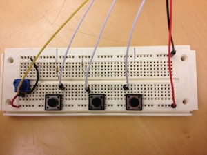
Instructions (image attached):

  1. Attach three buttons to breadboard, spaced comfortably apart.
  2. Attach a pulldown resistor between each of the buttons and ground.
  3. Connect ground to Arduino.
  4. Attach 5V line to the other side of the buttons.
  5. Attach signal lines between the resistors and buttons and run to digital pins 6, 8, and 10 on the Arduino.
  6. Attach potentiometer to Analog 0, ground, and 5V
2013-03-06 23.01.43

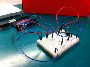
Reference Image for Circuitry

Source Code:
buttons.ino

#include 

int b1 = 6;
int b2 = 8;
int b3 = 10;
int b1Reading;
int b2Reading;
int b3Reading;
int curReading;
int lastReading;
int potPin = 0;
int fixed;

void setup(void) {
  MIDI.begin(0);
  Serial.begin(9600);
  pinMode(b1, INPUT);
  pinMode(b2, INPUT);
  pinMode(b3, INPUT);
}

boolean b1Last = false;
boolean b1New = false;
boolean b2Last = false;
boolean b2New = false;
boolean b3Last = false;
boolean b3New = false;

void loop(void) {
 
curReading = analogRead(potPin);
if (abs(curReading - lastReading) > 2) {
  fixed = map(curReading, 0, 1023, 0, 250);
  Serial.print("p");
  Serial.print(fixed);
   Serial.println(" ");
}

lastReading = curReading;
b1Reading = digitalRead(b1);
if (b1Reading == HIGH) { 
  b1New = true;
}
else {b1New = false;}

b2Reading = digitalRead(b2);
if (b2Reading == HIGH) { 
  b2New = true;
}
else {b2New = false;}

b3Reading = digitalRead(b3);
if (b3Reading == HIGH) { 
  b3New = true;
}
else {b3New = false;}

if( !b1Last && b1New) {
  Serial.println("1 ");  
}
if( !b2Last && b2New) {
  Serial.println("2 ");  
}
if( !b3Last && b3New) {
  Serial.println("3 ");  
}
b1Last = b1New;
b2Last = b2New;
b3Last = b3New;

delay(5);
}

beatlooper.ck

Shakers inst[16];
int filled[16];
0 => int count;
.125::second => dur step;
for(0 => int i;i  dac;
}
// create our OSC receiver
OscRecv recv;
// use port 6449
6449 => recv.port;
// start listening (launch thread)
recv.listen();
recv.event( "set, i" ) @=> OscEvent set;
<<>>;
fun void play() {
    while(true){  
        
        if(filled[count] == 1) {
            .9 => inst[count].energy;
            .8 => inst[count].noteOn;
            <<>>; 
        }
        step => now;
        if(filled[count] == 1) {
            .8 => inst[count].noteOff;
        }
        (count + 1) % 16 => count;
    }   
}
spork~ play();
while(true) {
    
    set => now;
    set.nextMsg();  //loop thing?
    1 => filled[count];
    set.getInt() => inst[count].preset;
    
    <<>>;   
}

looperknob.py

import serial
import OSC
import time

ser = serial.Serial('/dev/tty.usbmodemfa141', 9600)

client = OSC.OSCClient()
client.connect( ('127.0.0.1', 6449) )  
iset = OSC.OSCMessage()
iset.setAddress("set")
knob = OSC.OSCMessage()
knob.setAddress("knob")


while 1:
    line = ser.readline()
    if " " in line:
        if("p" in line):
            s = line.replace("p", "")
            print int(s)
            knob.append(int(s))
            client.send(knob)
            knob.clearData()
        else:
            print int(line)
            iset.append(int(line))
            client.send(iset)
            iset.clearData()

L2: Expressive Chaos

Krithin Sitaram (krithin@)
Amy Zhou (amyzhou@)
Daniel Chyan (dchyan@)
Jonathan Neilan (jneilan@)
Thomas Truongchau (ttruongc@)

Group 11

Expressive Chaos
Video Link
We built an instrument that combines multiple sensors that provides a unique experience for a performer to produce multiple sounds. We decided upon this design in order to challenge ourselves to use every sensor on the parts list and we believe we were successful in constructing this instrument. The final product does look a bit messy and it would be better if we had an enclosure in order to have a more pleasant looking instrument.

Instructions to Build:
Use 2 breadboards. On one breadboard, put flex sensor on the other breadboard, place the slide sensor, light sensor, and the button. The flex sensor, light sensor, and button are connected through pull-down resistors of 10k Ohms, 330 Ohms, and 330 Ohms respectively. Each are connected to an analog input pin.

Source Code:

const int INPINS[] = {A0, A1, A2, A3};
const int MAXVALUES[] = {950, 400, 1023, 320};
const int MINVALUES[] = {610,0,0,140};
const int BUZZER = 8;

void setup() {
  pinMode(BUZZER, OUTPUT);
  Serial.begin(9600);
}

void loop() {
  for (int i = 0; i < 4; i++) { // hardcoded len(INPINS);
    double outtone = (analogRead(INPINS[i]) - MINVALUES[i]) * ((double)1000/(MAXVALUES[i] - MINVALUES[i])) + 440;
    tone(BUZZER, outtone, 100);
    Serial.println(analogRead(INPINS[i]));
      Serial.println(outtone);
    delay(130);
    noTone(BUZZER);

  }
  Serial.println();
  Serial.println();

}

Prototype 1: Expressive Maraca
Video Link
This instrument simulates a maraca electronically using an accelerometer and buzzer.

Source Code:

#include <Math.h>

const int groundpin = A2; // analog input pin 2
const int powerpin = A0; // analog input pin 0
const int xpin = A5; // x-axis of the accelerometer
const int ypin = A4; // y-axis
const int zpin = A3; // z-axis 
int BASELINE; // baseline for accelerometer

void setup()

{
 Serial.begin(9600);

 pinMode(groundpin, OUTPUT);
 pinMode(powerpin, OUTPUT);
 digitalWrite(groundpin, LOW); 
 digitalWrite(powerpin, HIGH);
 BASELINE = analogRead(xpin);

}

void loop()
{

 Serial.print(analogRead(xpin));  // print the sensor values:
 Serial.print("\t");  // print a tab between values:
 Serial.print(analogRead(ypin));
 Serial.print("\t");   // print a tab between values:
 Serial.print(analogRead(zpin));
 Serial.println();
 delay(5); // delay before next reading:

 double diff = fabs(analogRead(xpin) - BASELINE);
 if (diff > 150) {
    tone(10, 440);
    delay(10);
    noTone(10);
 }

}

Prototype 2: Expressive Siren
Video Link
This instrument produces a siren sound with an accelerometer and buzzer.

Source Code:

#include <Math.h>

const int groundpin = A2; // analog input pin 2
const int powerpin = A0; // analog input pin 0
const int xpin = A5; // x-axis of the accelerometer
const int ypin = A4; // y-axis
const int zpin = A3; // z-axis 
int YBASELINE; // baseline for accelerometer
int XBASELINE; 

void setup()

{
 Serial.begin(9600);

 pinMode(groundpin, OUTPUT);
 pinMode(powerpin, OUTPUT);
 digitalWrite(groundpin, LOW); 
 digitalWrite(powerpin, HIGH);
 XBASELINE = analogRead(xpin);
 YBASELINE = analogRead(ypin);
}

void loop()
{
 double xchange =  fabs(analogRead(xpin) - XBASELINE); 
 double ychange =  fabs(analogRead(ypin) - YBASELINE); 
 double diff = sqrt(xchange*xchange + ychange*ychange);

 double ytone = (analogRead(xpin) - 272) * (440/137) + 440;
 Serial.println(ytone);
 tone(10, ytone);

}

int roundToTenth(double a) {
  double t1 = a / 10;
  double t2 = floor(t1) * 10;
  Serial.print(t2);
  Serial.println();
  return t2;

}

Prototype 3: The Metronome (which becomes Expressive Chaos)
Video Link
This metronome turns into our Expressive Chaos instrument.

Source Code:

const int INPINS[] = {A0, A1, A2, A3};
const int MAXVALUES[] = {950, 1023, 1023, 320};
const int MINVALUES[] = {610,0,0,140};
const int BUZZER = 8;

void setup() {
  pinMode(BUZZER, OUTPUT);
  Serial.begin(9600);
}

void loop() {
    tone(BUZZER, 440, 100);
    delay(1000);
    noTone(BUZZER);

}

Parts List for Expressive Chaos
– 1 Flex Sensor
– 1 Slide Sensor
– 1 Photocell
– 2 Resistors – 330 Ohms
– 1 Resistor – 10k Ohms
– 1 Buzzer
– 1 Button
– 2 Breadboards
– Arduino

Sensor Wonderland

Group #6: Gene Mereweather, Alice Fuller, Phillip Oasis and Rodrigo Menezes

Our final instrument used a whammy pedal and a slide sensor to modify the pitch and length of each buzz on our buzzer. The user would control the whammy pedal with their feet and the slide sensor with their finger on the desk. We were pretty satisfied with the overall results, especially with the functionality of the whammy pedal. If we put more effort into it, we would try to find a more natural way to change the time between buzzes.

Prototype 1: Whammy Pedal

This prototype used an empty box, a whiteboard eraser, a light sensor, a big spring and a buzzer to create a “whammy pedal”. When the box is pressed down, the light sensor recognizes that there is less light in the box. The code in the prototype uses the change in light to modify the tone and frequency of the buzzing. We used both a Piezo sensor and buzzer for sound.

Prototype 2: Light-ccordian

To continuing playing around with the light sensor, we put holes in a rectangular box down the center. The less light received by the light sensor, the smaller the pitch of each buzz emitted by the buzzer.

Prototype 3 and Final Instrument: Slide Pitch + Whammy Pedal

We added an additional touch sensor to prototype 1 and re-worked the software, so that the light sensor would control the length of each buzz and the slide potentiometer would control the pitch. It worked really well and we were able to perform with it, so we chose this to be our final instrument. We kept adapting the code until we were satisfied with the musicality. In the following video, Gene performs with our final instrument:

List of parts used

  • Arduino, wires, two breadboards
  • Slide potentiometer
  • Buzzer + 330 Ohm resistor
  • Piezo sensor
  • Light sensor + 10k Ohm resistor
  • Box, whiteboard erase marker, spring and duct tape (for the whammy pedal)

How to build it

We put the spring on the whiteboard erase marker using duct tape, and placed it within a small square box. The light sensor was placed with the 10k Ohm resistor in one breadboard within the box. Wires connected this to our analog reads. We put the slide potentiometer, piezo sensor and buzzer on the other bread board. The buzzer required a 330 Ohm resistor and was connected to a digital pin. The slide potentiometer was in another analog pin and the piezo sensor was connected to another digital pin.

View post on imgur.com

View post on imgur.com

View post on imgur.com

Source code

const int lightAnalogPin = 0; // FSR is connected to analog 0
const int slideAnalogPin = 1;
int slideReading;    // the analog reading from the slide pot
int lightReading;    // the analog reading from the light resistor divider

const int piezoPin = 9;
const int buzzerPin = 5;

int duration; // time that each note lasts
const int betweenNotes = 0; // time between notes

void playTone(int tone, int duration) { // adapted from Arduino tutorials
  for (long i = 0; i < duration * 1000L; i += tone * 2) {
    digitalWrite(piezoPin, HIGH);
    delayMicroseconds(tone);
    digitalWrite(piezoPin, LOW);
    delayMicroseconds(tone);
  }
}

void setup(void) {
  pinMode(piezoPin, OUTPUT);
  pinMode(buzzerPin, OUTPUT);
  Serial.begin(9600);
}

void loop(void) {
  lightReading = analogRead(lightAnalogPin);
  slideReading = analogRead(slideAnalogPin);
  Serial.print("Analog reading = ");
  Serial.println(slideReading);

  duration = map(lightReading, 0, 1023, 500, 10); // low light = shorter note

  // adapted from Arduino tutorials
  int buzzerValue = map(slideReading, 0, 1023, 16, 7902); // low light = low pitch
  tone(buzzerPin, buzzerValue, 100);
  int piezoValue = map(slideReading, 0, 1023, 1915, 956); // low light = low pitch
  playTone(piezoValue, duration);
  delay(duration);
}