Colleen Caroll, Angela Dai, Connie Wan, Edward Zhang
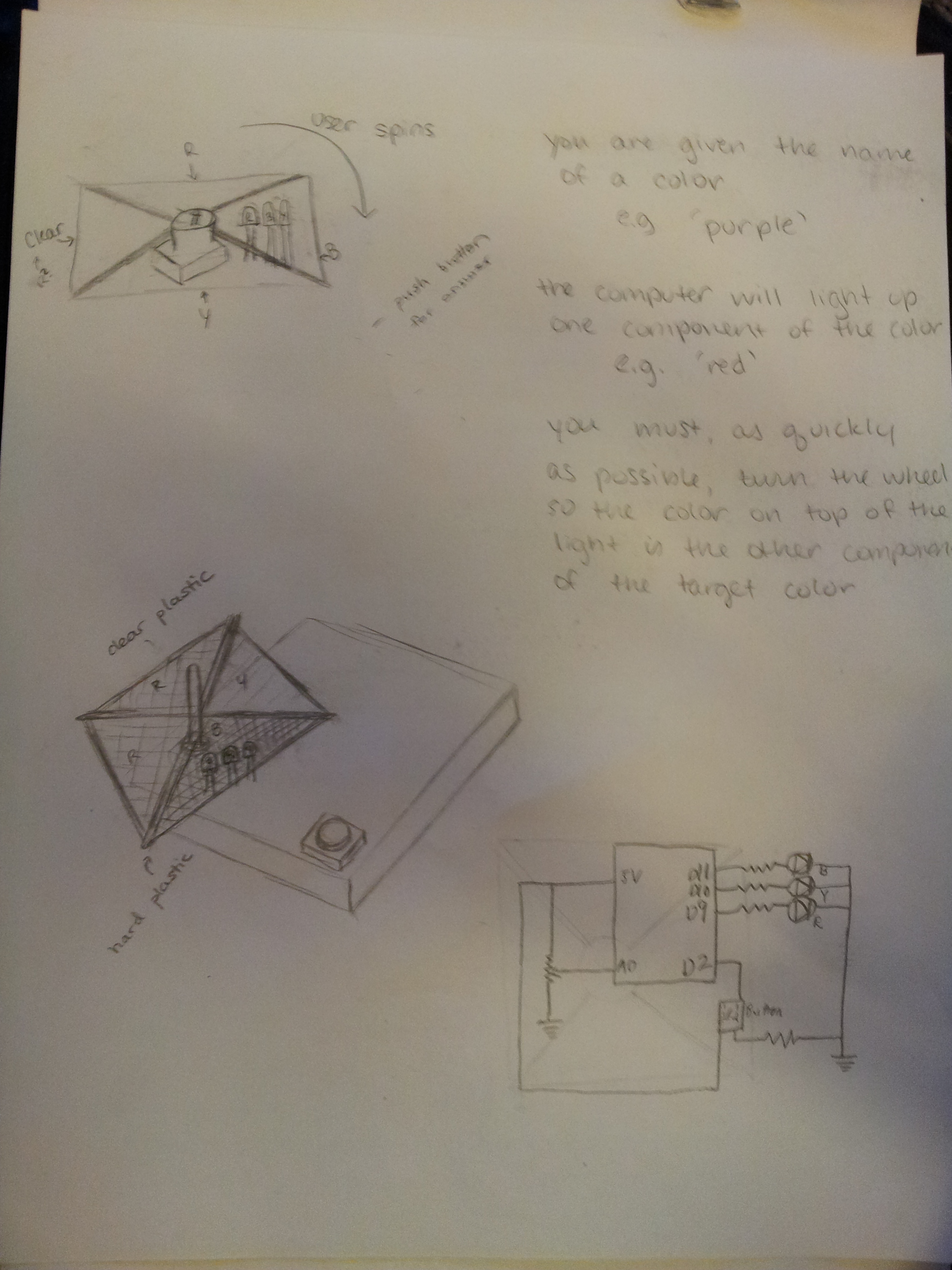
The Color Wheel is a game that challenges players to create a specified color using LEDs and colored filters. It is a fun and easy way for children to learn about the primary colors and the secondary colors that they create! The system is great because it is simple to use and understand. A color appears on the computer screen (e.g. “purple”), one colored led lights up on the board (e.g. red lights up), and then the user only has to turn the color wheel so that the color on the wheel mixes with the light to create the desired color (e.g. player turns the wheel to blue, thus making purple). It was, however, difficult to get a medium that would diffuse the LED properly so that color of the light and the filter would mix properly to the desired color. The LED is so focused that it was a challenge to get it to blend well with a material. We tried saran wrap, copy paper, toilet paper, and finally–thin sketch paper with watercolor to increase the translucence slightly. We put a lot of effort into finding the most effective and aesthetically pleasing diffuser, as it an integral part of the function of our game. Our game works well (we have played several successful games) but would be even better with a more diffuse light (or another filter) that blended better.
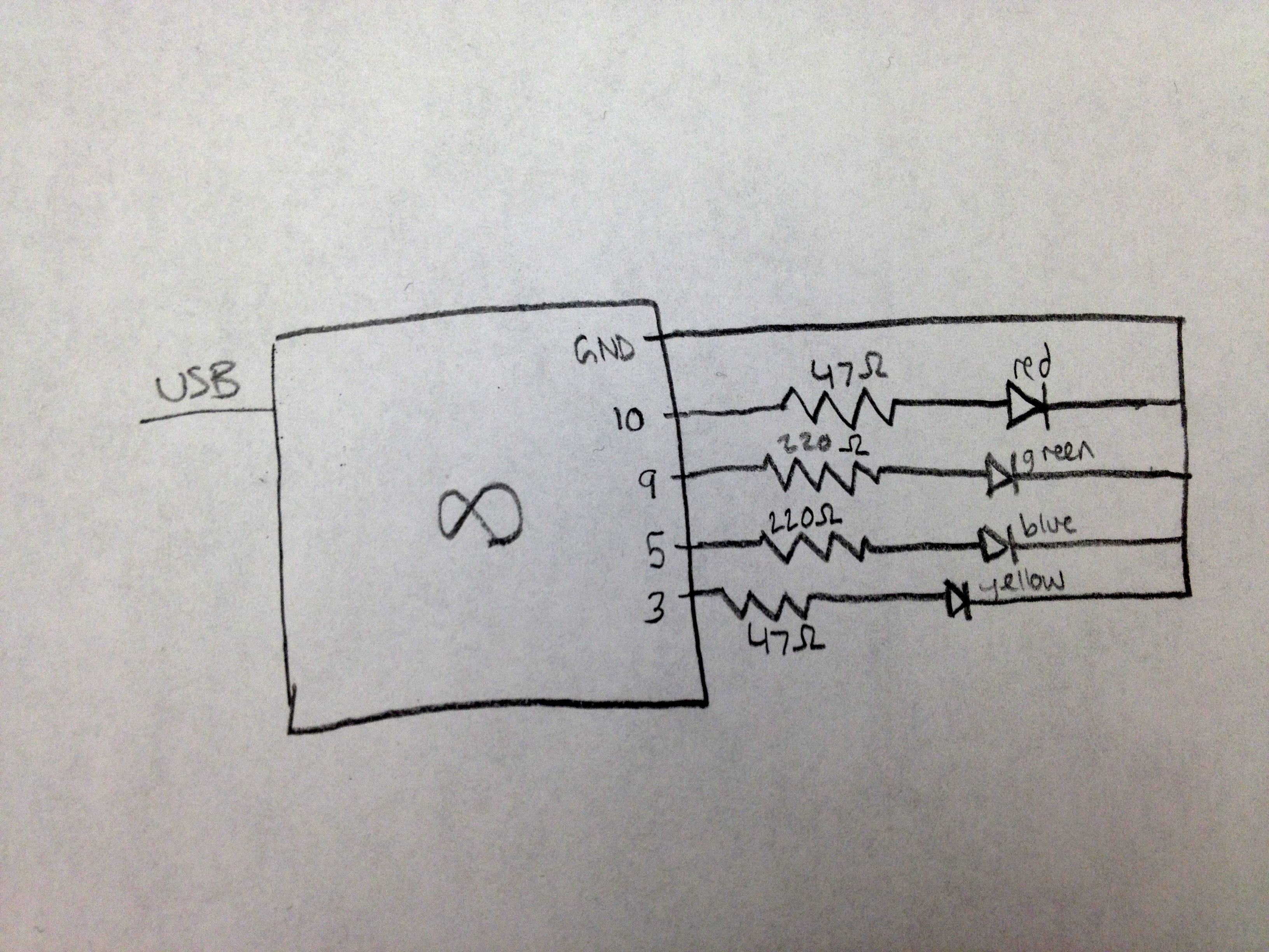
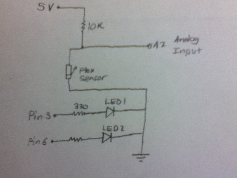
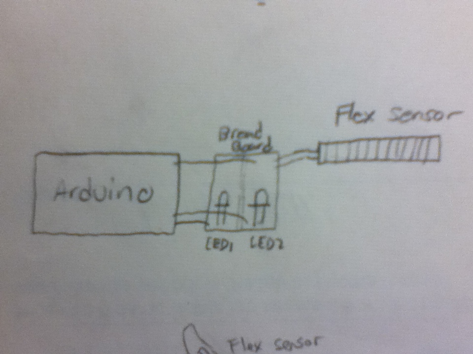
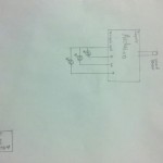
Diagrams:
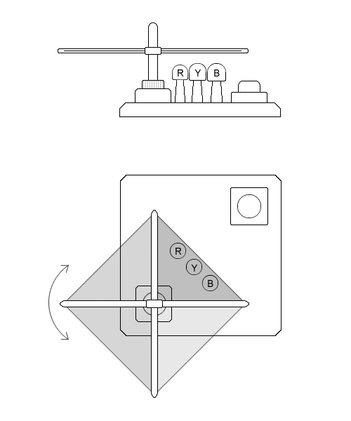
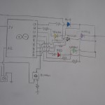
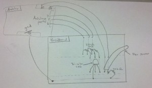
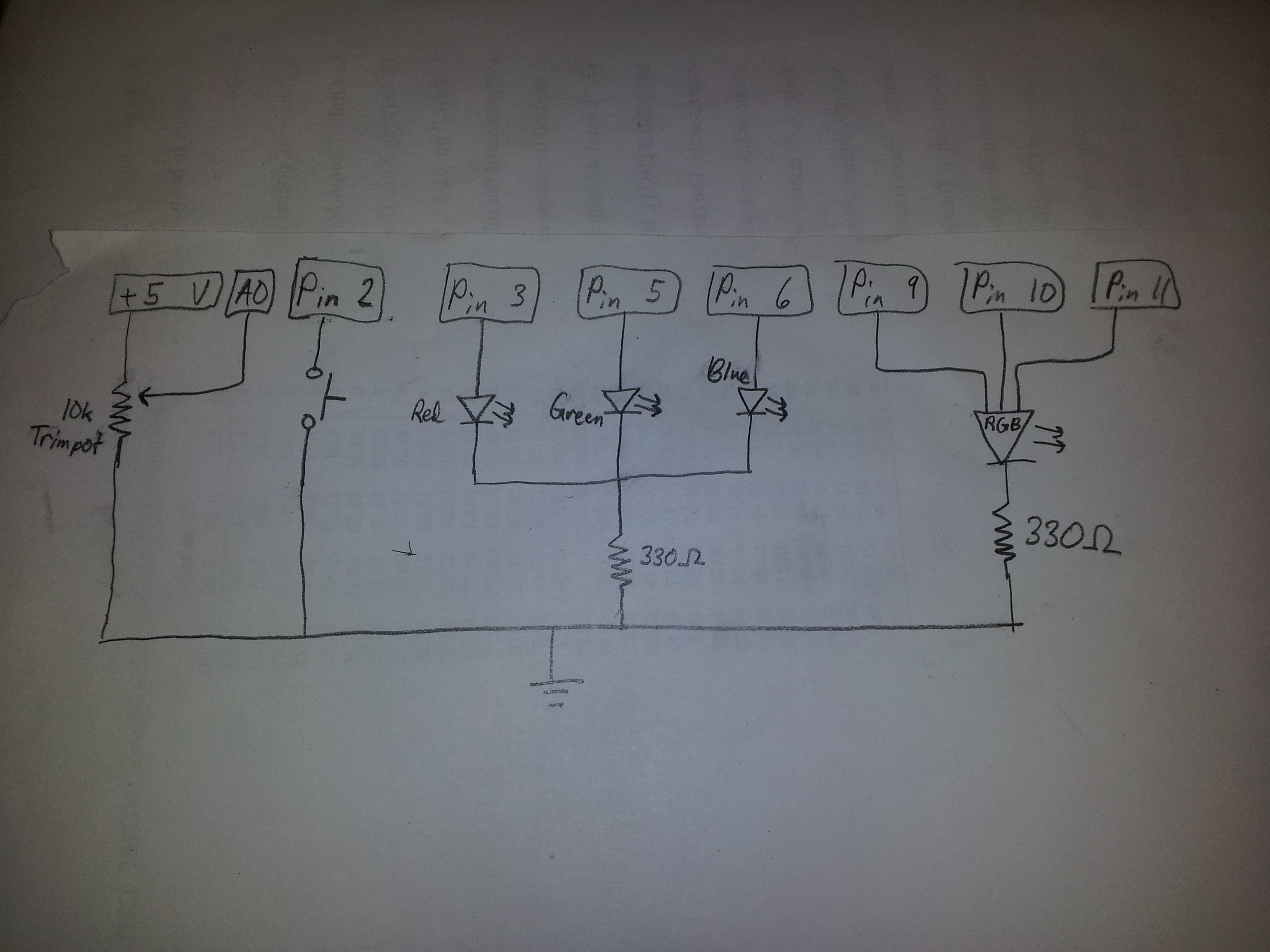
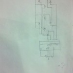
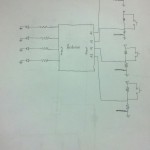
This schematic shows the rotating diffusing filter (mounted on a potentiometer) atop the LEDs, with the “Submit” push button on the side.
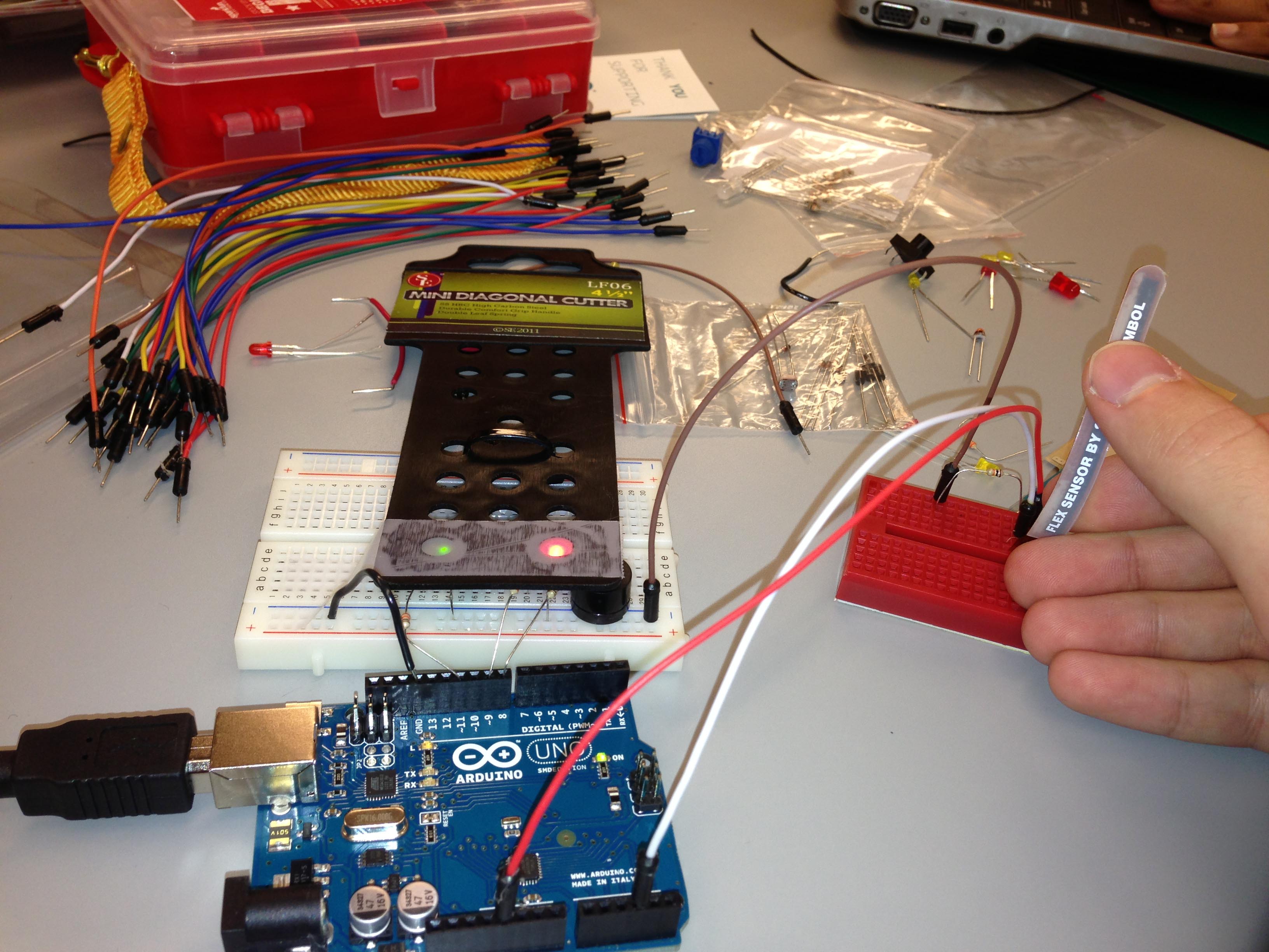
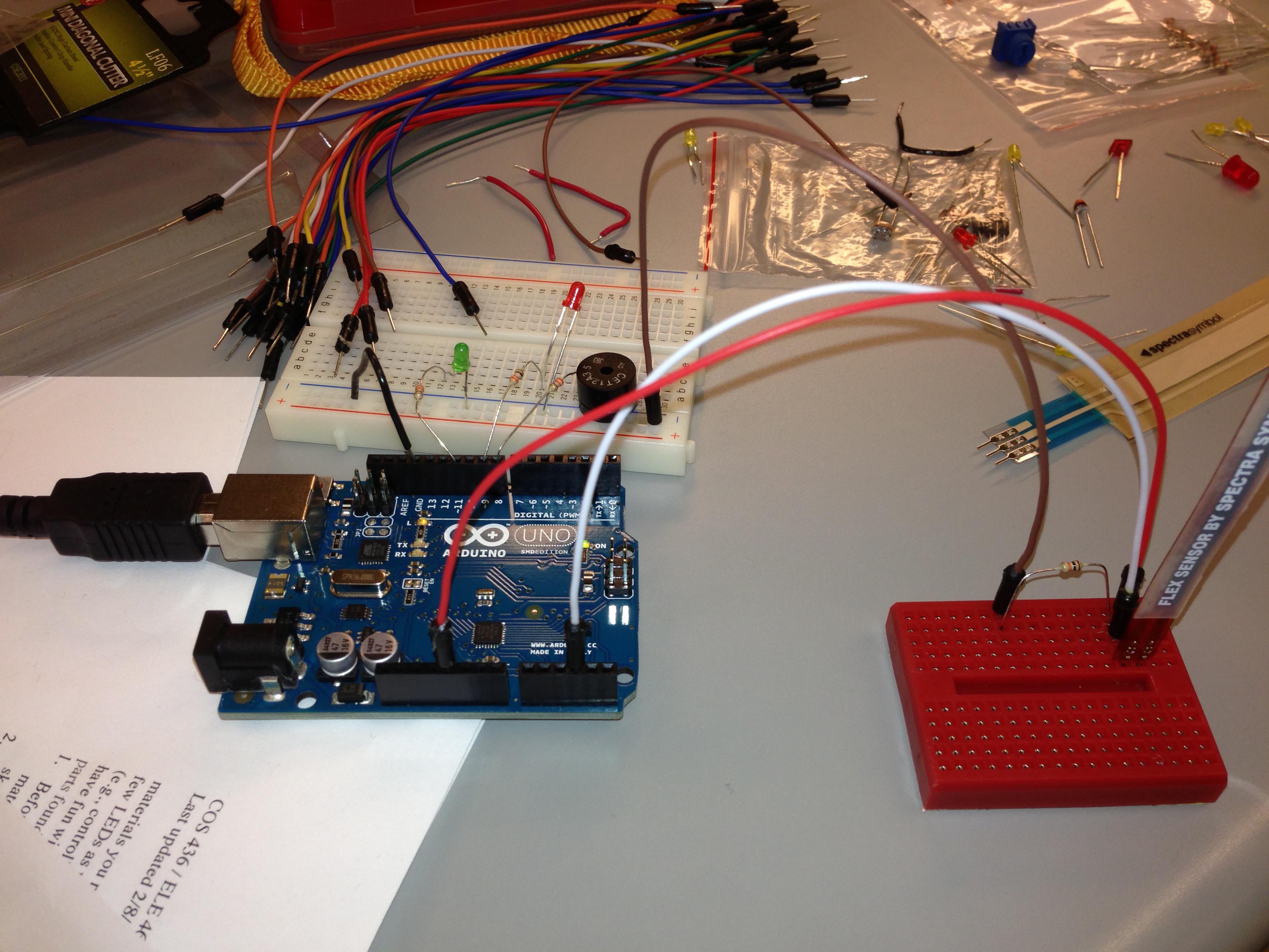
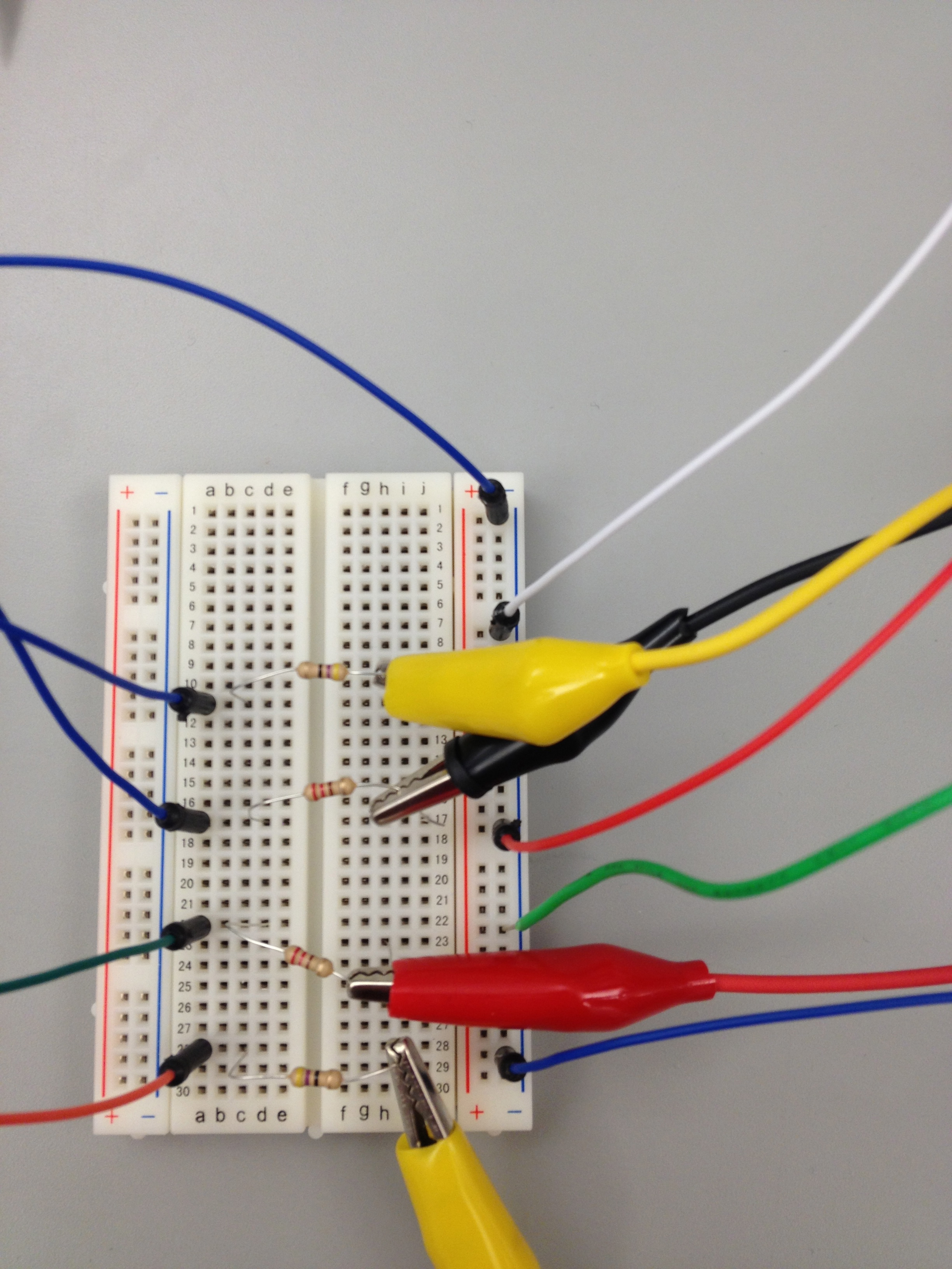
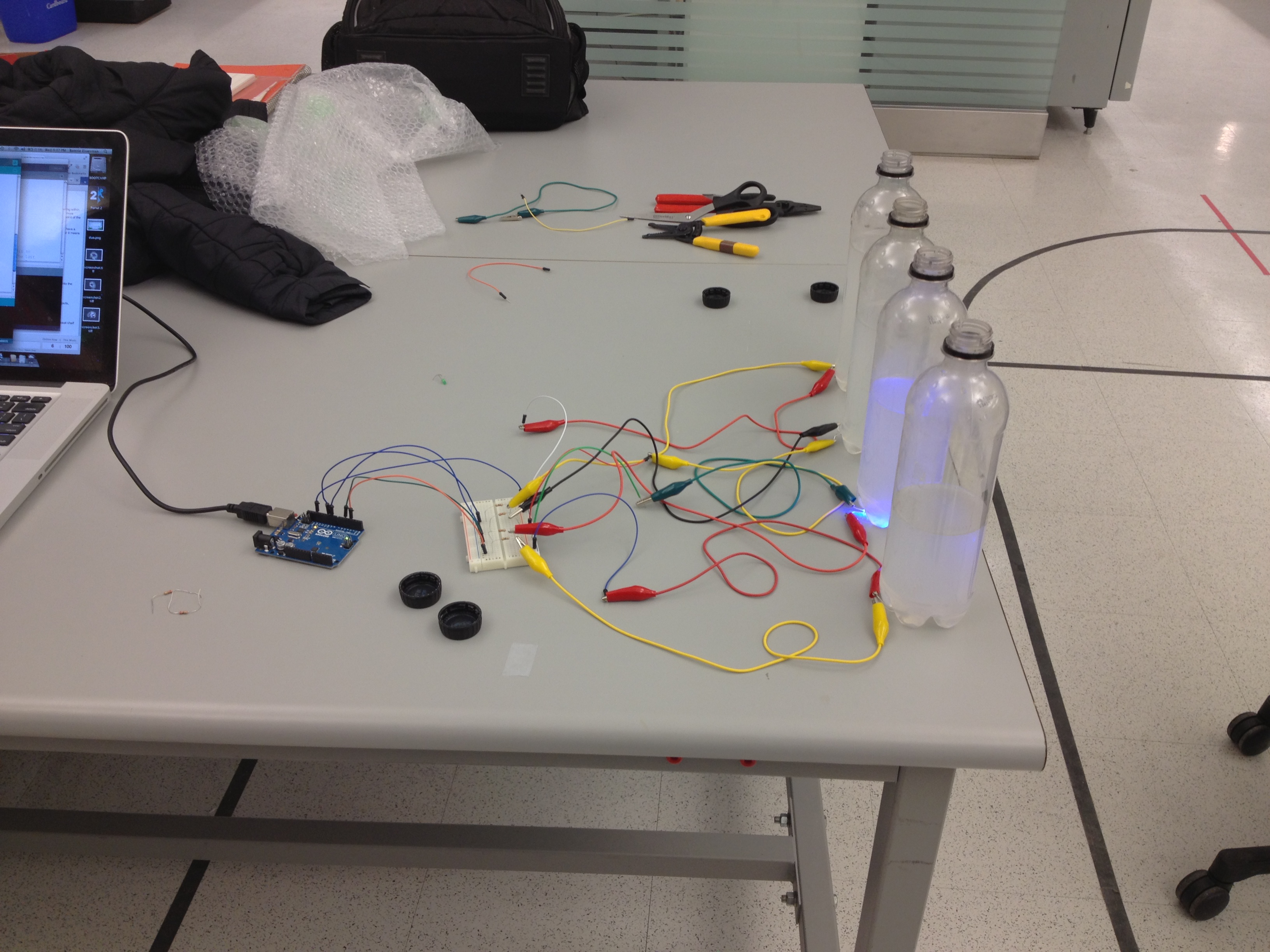
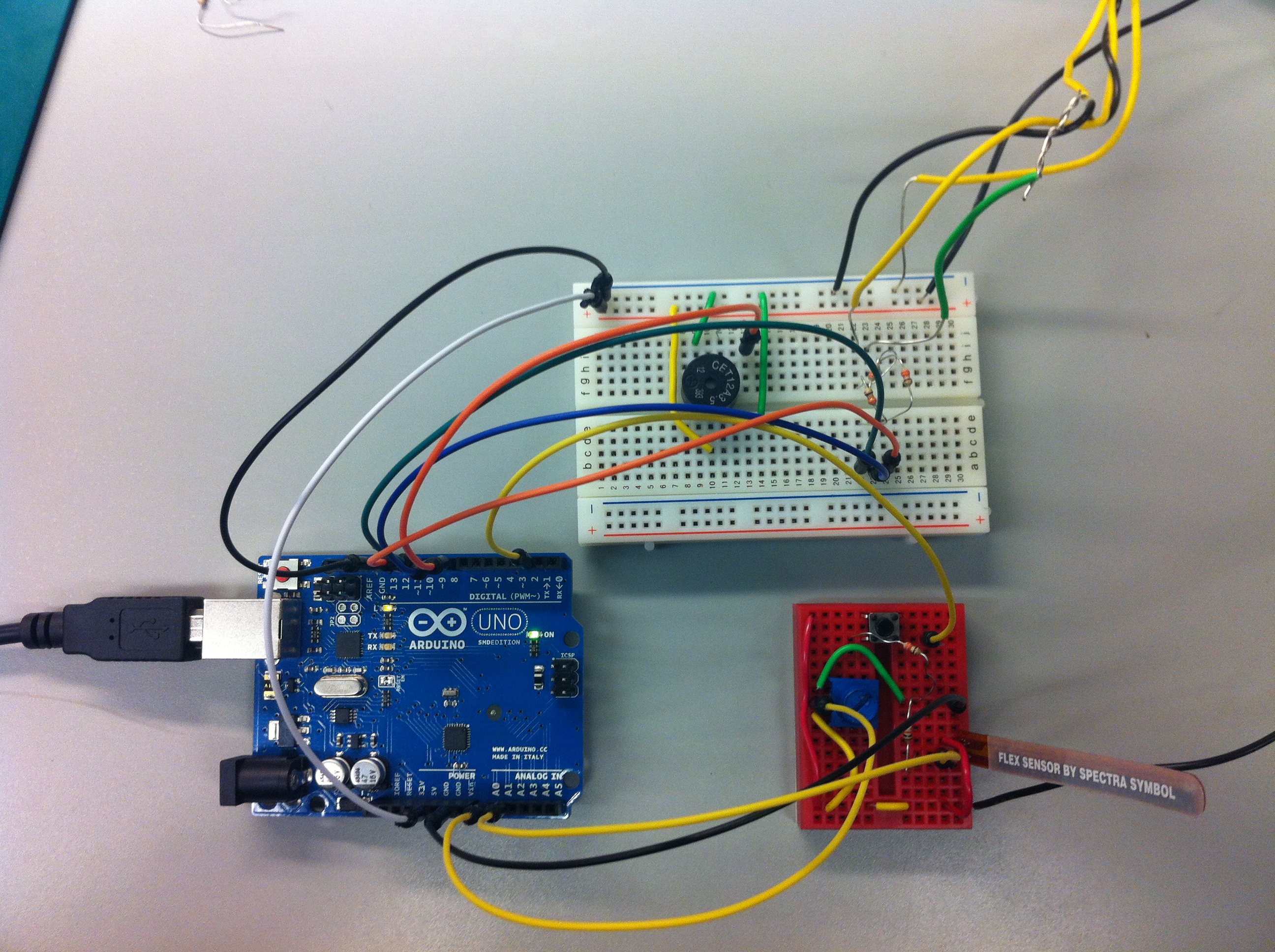
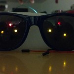
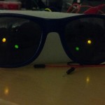
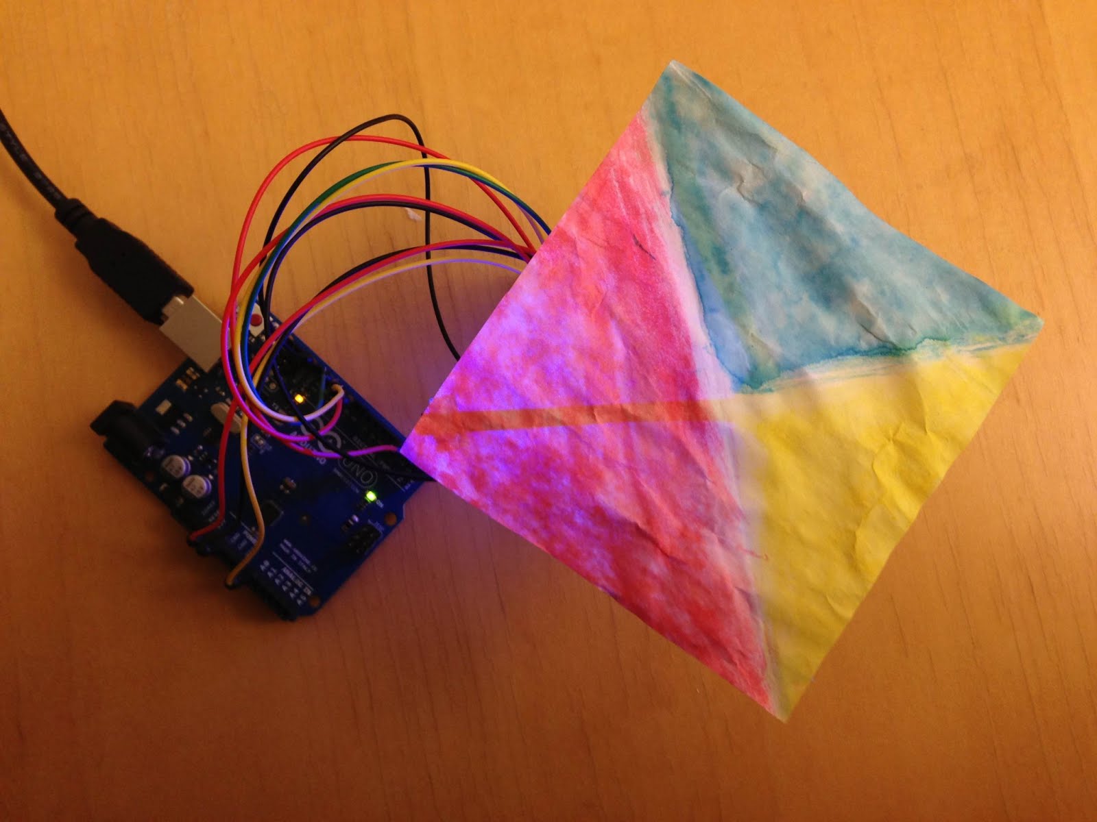
Images of Final System:
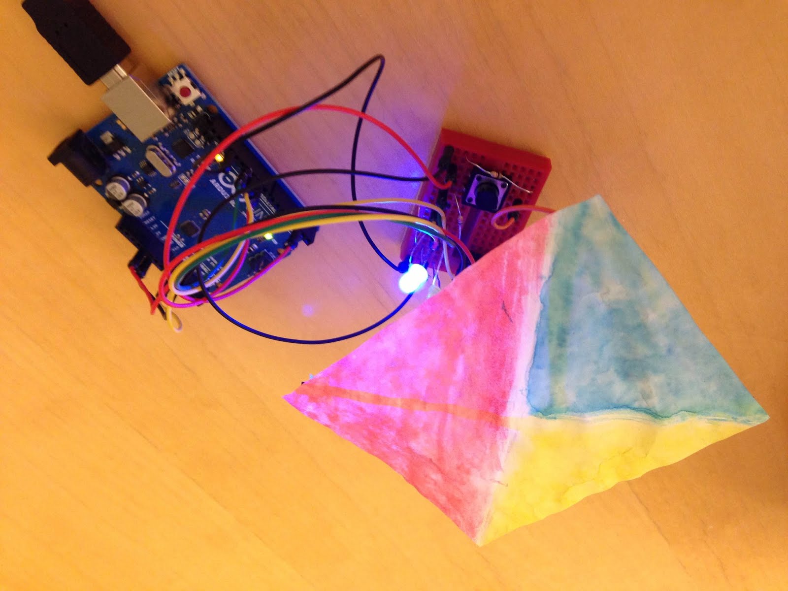
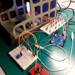
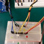
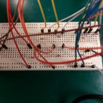
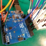
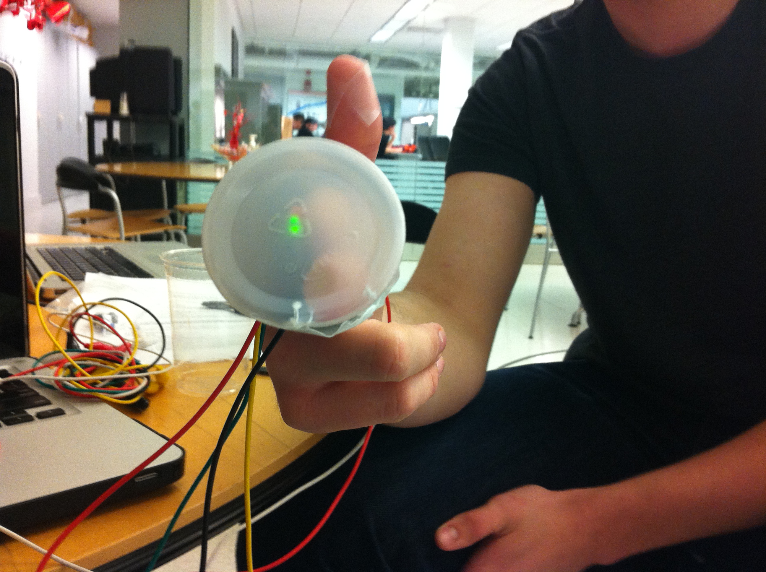
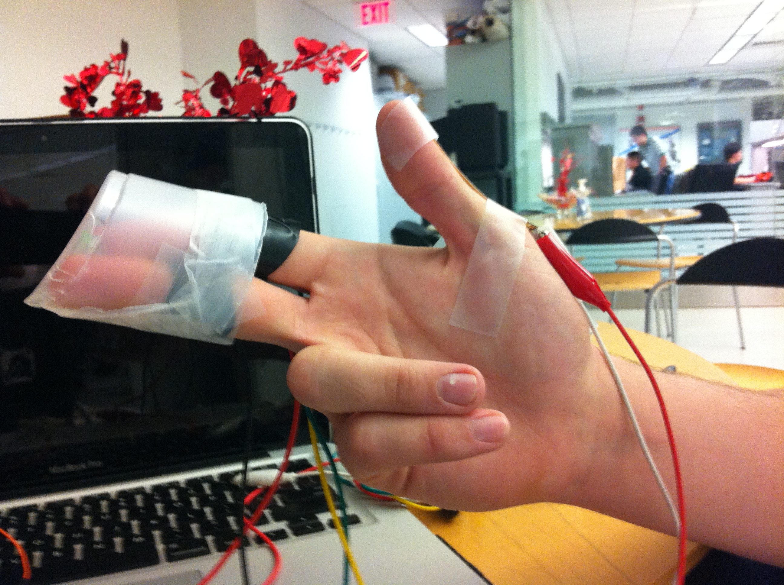
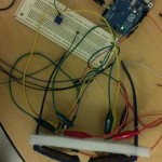
The electronics. Turn the paper filter (which is connected to a potentiometer) so that the blended color with the displayed LED light becomes a prompted color. Push the button to submit your guess.
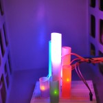
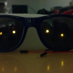
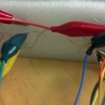
For a prompted color of purple and a blue LED light, we turn the paper filter to red so that a purple color is seen.
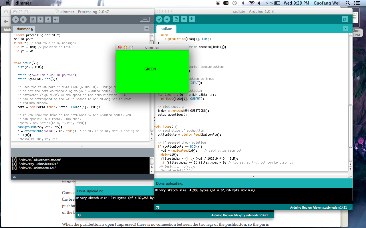
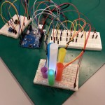
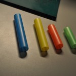
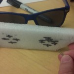
We used processing to display a prompt color to achieve (in this case green) using the displayed LED color and the filter paper.
Parts List:
Electronics:
- Red, Yellow, and Blue LED (or a tricolor LED + yellow LED)
- 3x 330Ω Resistors
- 1x 10kΩ Resistor
- Linear Potentiometer
- 12mm button
- Breadboard
- Arduino Uno
Other:
- Straw
- Paper
- Red, yellow, and blue markers
- Duct Tape
Instructions:
- Connect each of the LEDs to ground through a 330Ω resistor. Connect the positive side of the red LED to digital port 9, the yellow LED to digital port 10, and the blue LED to digital port 11.
- Connect the middle pin of the potentiometer to A0 (analog input 0) on the Arduino, and the outer pins to ground and 5V power,
- Connect one pin of the button to 5V power, another to digital pin 2, and another to ground through a 10kΩ resistor.
- Tape the end of the straw to the potentiometer, so that the straw sticks straight out of the knob. The tape should be strong enough such that turning the tape turns the knob of the potentiometer and the straw.
- Cut the other end of the straw lengthwise such that it splits into four strips. Flatten out the strips so they are perpendicular to the rest of the straw.
- Using the markers, color a square of paper (approx. 10cm x 10cm) so that approximately a third is red, a third yellow, and a third blue. The paper and markers should result in something that, when the LEDs shine through it, the colors blend into the primary combinations (green, purple, orange).
- Attach this paper to the straw strips using tape. The potentiometer-straw diffuser should be positioned such that the LEDs are underneath the paper to one side, and turning the potentiometer places each of the different colored paper regions over the LEDs.
Source Code:
Arduino Code
/**
* arduino
**/

/*
 Radiate, L0
 */

int val = 0;       // variable to store the value coming from the sensor
int leds[] = {9, 10, 11}; // LED pins
int NUM_LEDS = 3;           // number of LEDs
const int buttonPin = 2;
int buttonState = 0;

enum COLOR {
  RED,
  YELLOW,
  BLUE,
  ORANGE,
  GREEN,
  PURPLE,
  NUM_PROMPTS
};
const int NUM_QUESTIONS = 9;
int question_leds[] =    {RED, RED,    RED,    YELLOW, YELLOW, YELLOW, BLUE, BLUE,   BLUE};
int question_prompts[] = {RED, ORANGE, PURPLE, YELLOW, ORANGE, GREEN,  BLUE, PURPLE, GREEN};
int solutions[] =        {RED, YELLOW, BLUE,   YELLOW, RED,    BLUE,   BLUE, RED,    YELLOW};

int index = 0; // index of question
int filterindex = 0;

void setup_question()
{
  // turn on/off corresponding leds
  for (int i = 0; i < NUM_LEDS; i++) {
    if (i == question_leds[index]) {
      digitalWrite(leds[i], HIGH);
    }
    else
      digitalWrite(leds[i], LOW);
  }
  Serial.println(question_prompts[index]);
}

void setup()
{
  // initialize the serial communication:
  Serial.begin(9600);

  // initialize pushbutton as input
  pinMode(buttonPin, INPUT);

  // initialize led outputs:
  for (int i = 0; i < NUM_LEDS; i++)
    pinMode(leds[i], OUTPUT);

  // pick question
  index = random(NUM_QUESTIONS);
  setup_question();
}

void loop() {
  // read state of pushbutton
  buttonState = digitalRead(buttonPin);

  // if pressed check solution
  if (buttonState == HIGH) {
    val = analogRead(A0);    // read value from pot
    delay(10);
    filterindex = (int) (val / 1023.0 * 3 + 0.5);
    if (filterindex == 3) filterindex = 0; // two red so that pot can be circular
   /* Serial.print(val);
    Serial.print(" ");
    Serial.print(filterindex);
    Serial.print(" ");
    Serial.println(solutions[index]); */
    if (filterindex == solutions[index]) {
      // correct! new question
      index = random(NUM_QUESTIONS);
      setup_question();
    }
  }
}
Processing Code:
/**
processing -- displays colour prompts
**/

 import processing.serial.*;
 Serial port;
 PFont f; // font to display messages
 int xp = 100; // position of text
 int yp = 70;

 void setup() {
   size(256, 150);

   println("Available serial ports:");
   println(Serial.list());

   port = new Serial(this, Serial.list()[4], 9600);

   // If you know the name of the port used by the Arduino board, you
   // can specify it directly like this.
   //port = new Serial(this, "COM1", 9600);
   background(255, 255, 255);
   f = createFont("Arial", 16, true); // Arial, 16 point, anti-aliasing on
   fill(0);
   //text("BEGIN", xp, yp);
 }

 void draw() {
 }

 void serialEvent(Serial myPort) {
   // get ascii string
   String instring = myPort.readStringUntil('\n');
   if (instring != null) {
     // trim off whitespace
     instring = trim(instring);
     int prompt = int(instring);
     drawbackground(prompt);
   }
 }

 void drawbackground(int prompt) {
   switch (prompt) {
     case 0:
     background(255, 0, 0);
     text("RED", xp, yp);
     break;
     case 1:
     background(255, 255, 0);
     text("YELLOW", xp, yp);
     break;
     case 2:
     background(0, 0, 255);
     text("BLUE", xp, yp);
     break;
     case 3:
     background(255, 127, 80);
     text("ORANGE", xp, yp);
     break;
     case 4:
     background(0, 255, 0);
     text("GREEN", xp, yp);
     break;
     case 5:
     background(255, 0, 255);
     text("PURPLE", xp, yp);
     break;
     default:
     background(0, 0, 0); // error
     fill(255);
     text("ERROR " + prompt, xp, yp);
     fill(0);
     break;
   }
 }
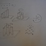
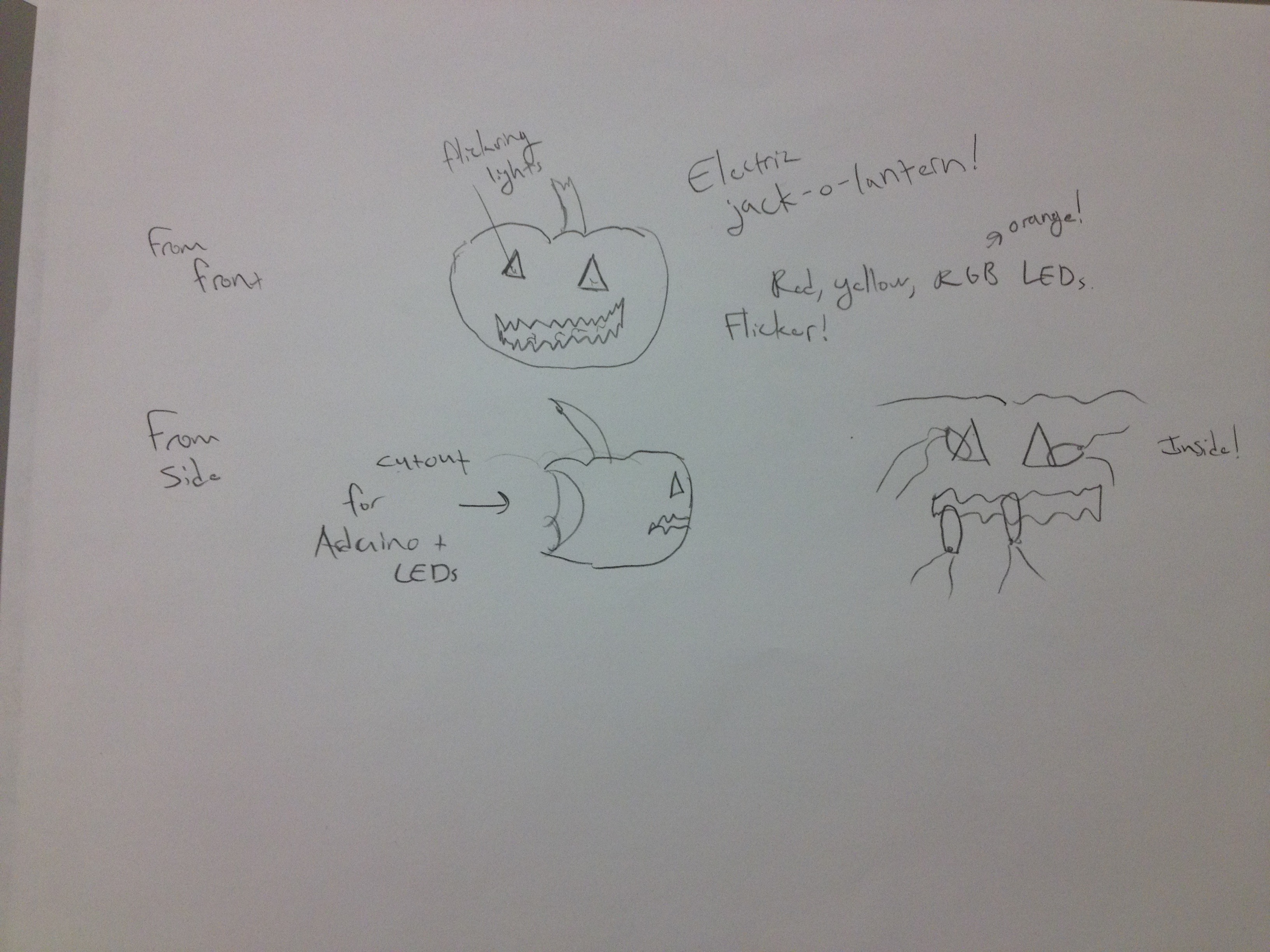
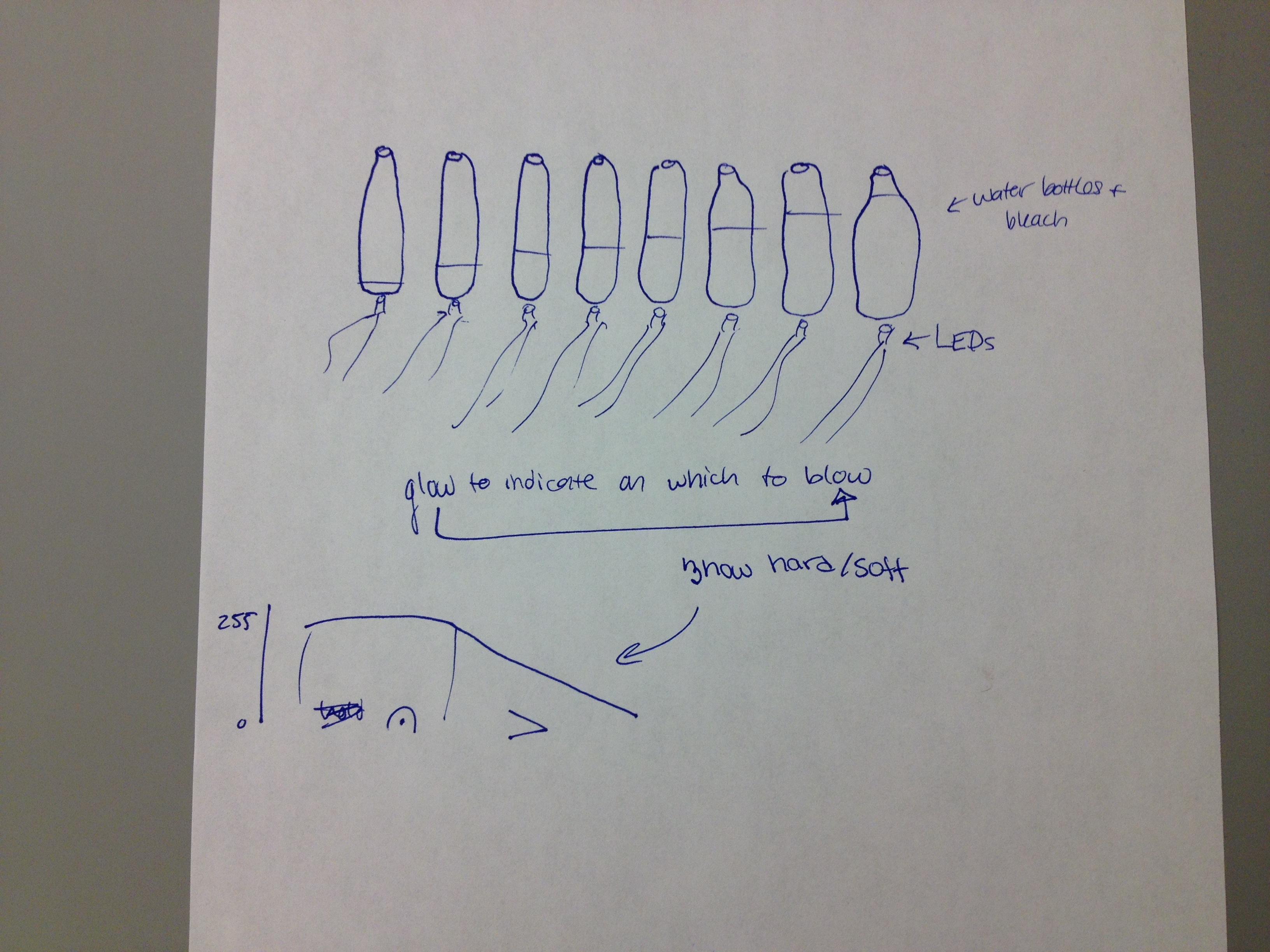
Other Ideas:
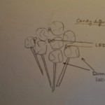
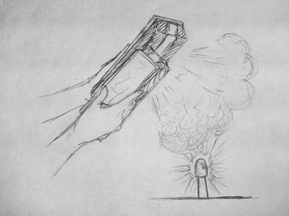
1. Chalk Dust Diffuser – Fill up a room with smoke (or chalk dust if a smoke machine is not readily available) and have multicolored LEDs changing color in sync to music. Awesome ambient lighting for a dance floor. This was a “diffuser-focused” idea.
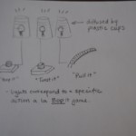
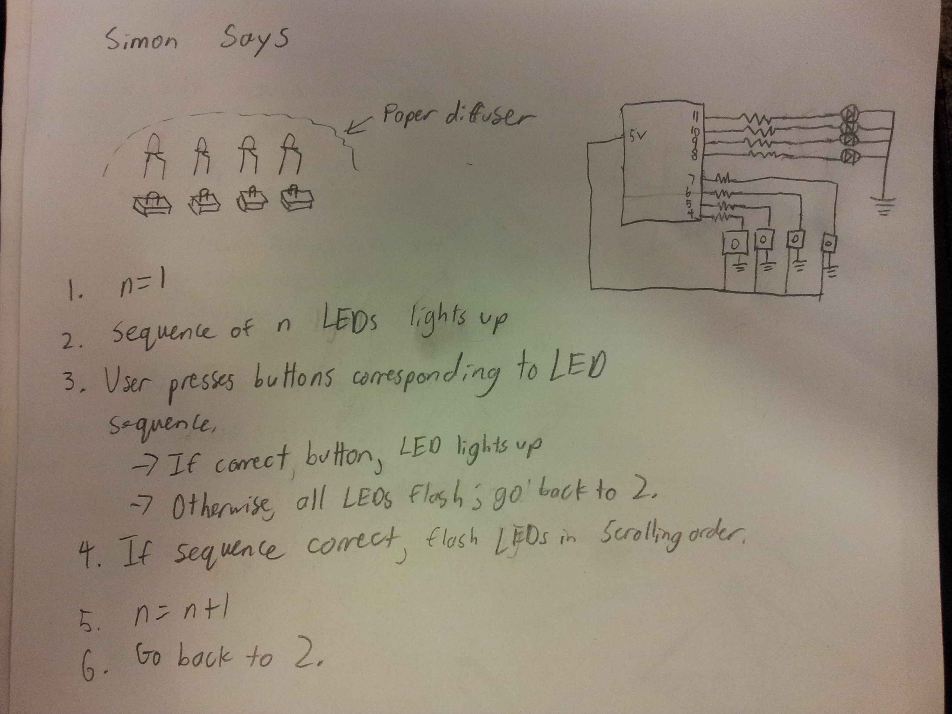
2. Simon Says – Using a set of buttons and colored LEDs, this game presents the user with sequences of colored lights of increasing length. They have to press the buttons corresponding to the appropriate lights in the correct order to advance. Unfortunately, while interactive, this didn’t really use the idea of a diffuser effectively.
3. Color matching game – This was an interactive game that had a diffuser as an integral part of the system. Create colors by moving the appropriately colored filter above the lit LED.