P1 – Team X

Group 10:

  • Osman Khwaja (okhwaja)
  • (av)
  • Igor Zabukovec (iz)
  • Junjun Chen (junjunc)

Brainstorming List

  1. Fingerprint sensing bike lock opener.
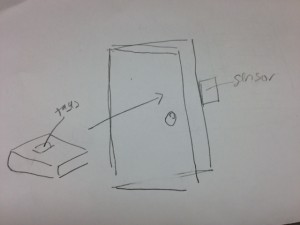
  2. Password gesture for opening a door.
    s4
  3. Darkness detecting light system for dorm rooms.
  4. Mood Llghting based on music.
  5. Device that automatically scrolls Facebook based on your eye position.
  6. Kindle that flips the page based on your eye position.
  7. Switch computer windows with gestures.
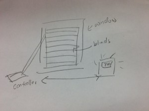
  8. Shades that close based on how bright it is outside.
    s5
  9. Shades on a timer for taking naps.
  10. Alarm clock that opens blinds.
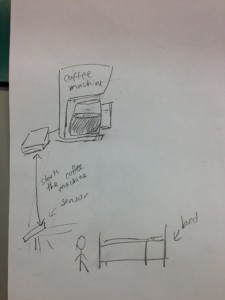
  11. Alarm clock that senses if you’re still in bed.
  12. Drawers that open pants/shorts, t-shirts/long sleeve based on the weather.
  13. Golf swing analyzer sunglasses.
  14. Smart foot stool that softens when you put your foot on it but stays rigid when other things are on it.
  15. Automatic coiling headphones that coil when you tug on them 3 times above a certain tension threshold.
  16. A mouthguard type sensor that tells if, after brushing your teeth, your mouth has an acceptable amount of plaque.
  17. A laptop monitor sensor that adjusts the angle of the screen based on your positioning in bed.
  18. A smartphone keyboard that adjusts to how you’re holding it (i.e. if holding it with one hand, will make a viable keyboard that caters to your one-handedness).
  19. When connecting external monitors to your laptop, you have to set your screen’s relative position. How about creating a system that that adjusts the external screen based on your position relative to the screen?
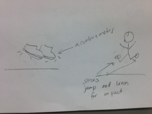
  20. A running shoe step monitor that tells a runner if they’re pronating their foot properly and recommends what type of shoe to buy.
  21. A gadget that lets you compare prices of a certain good while you’re at the store. Imagine you walk into Walmart and want to know if you’re getting a good deal on these headphones. Pull out smartphone/gadget, take picture, and a list of competitor prices shows up. (Kayak for real life).
  22. A toothbrush that tells you if you’re brushing your teeth too hard.
  23. Shoes that, as you’re jumping in the air, brace for impact by increasing cushion (I think laptops have something similar).
    s6
  24. A phone, that when placed on your bed, senses that you’re asleep and automatically moves calls to voicemail.
  25. Developing an alternative for knobs for music production programs (knobs are terrible to use with the mouse … we could just use physical knobs, but is there something more interesting?).
  26. Turn a laptop into a touch screen.
  27. Water dispenser that measure the amount of water in your cup (so it can stop pouring).
  28. Refrigerator that tracks what you have (and how much) and tells you what you need to buy.
  29. Sensor that reminds you to water your plants when the soil is dry
  30. Clothing that tells you if you’re slouching
  31. Clothing that indicates when it is stained / wrinkled / untucked, etc.
  32. Glasses that indicate whether or not you are straining your eyes too much (for example if you spend a lot of time in front of your computer screen).
  33. Headwear to help blind people navigate (senses when there is something in their path)
  34. Sound visualizer: Turn sounds to colors (for deaf people, or just to visualize sounds)
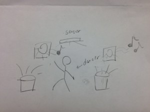
  35. System for dancers to learn moves that is synchronized to music. i.e. if they practice moves slowly, the music will play slowly, if they stop, it stops, etc.
    s2
  36. Similarly, an interactive system that responds to a dancer’s movements by generating both sound and visuals, allowing the dancer to control an entire multimedia performance (not necessarily just for practice).
  37. A similar system that compares a dancer’s moves against a previously recorded prototype (say by a teacher), so it can show mistakes in practice.
  38. A similar system for musicians to practice with an accompaniment track (slows down when they do, etc.)
  39. System that tells you if you have everything you need when you leave your room
  40. System that helps you find stuff in your room
  41. Live responsive software to music for a party : visuals are created according to the music played by the band/dj : sound, patterns, volumes. Possibility to use machine learning algorithms so that the software could recognize patterns in music
  42. Live responsive software to people’s movement in space for party: create visuals according to their movements: combining micros and kinects and use effects.
  43. Combine 40 and 41 : create a whole integrated systems for parties, where the experience keeps changing.
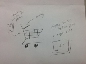
  44. Tools on shopping carts that reads your shopping list on a USB key. Then minimize the distance in the shopping mall and tells you where to go exactly on a screen placed on the shopping cart.
    s3
  45. Shopping cart as above, but instead of just telling you where to go, drives itself following the calculated path.
  46. Bike padlocks that have heating function (using a battery) so that the lock does not get stuck when it freezes (this happened to me a few times and it is very annoying).
  47. Electronic remote that can be used for all sorts of appliances: control your coffee machine, tv radio, etc.
  48. Same idea, except using voice and gesture recognition:  by saying “coffee”, “TV”, etc. turn things on or off, and by raising or lowering your arm change the volume (for example).
  49. Tool to plug and heat the coffee machine and make your coffee when your alarm clock goes off or when you go out of bed (in connection with idea 11) so that you do not have to wait in front of your coffee machine.
    s1
  50. System to drive a car using only eye movements, for paraplegics.
  51. Program that allows your to chance the source code file that you are working on without using the keyboard, so that you separate the functions of writing code and of choosing the file.
  52. A new way of accessing different directories on the computer that simulates files organized in a 3d space.

Idea Chosen

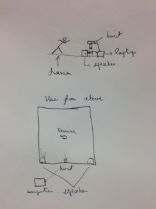
We chose idea #35: System for dancers to learn moves that is synchronized to music (i.e. if they practice moves slowly, the music will play slowly, if they stop, it stops, etc). We chose this because this (more than many of our other ideas) applies to a specific target user group. We also think that learning moves is a real world problem that our system could realistically help solve. Our system wouldn’t interfere much with users’ normal practice, which means it wouldn’t be hard for them to use. Also, since there are many dancers on campus, we would have access to the target user group for testing. It seems feasible in terms of budget, as it wouldn’t require very many parts. It would be a Kinect-based application, but as a second idea, we could also use tethers and other sensors (large flex sensors, etc). It also seems feasible in terms of work, and it is also a good starting point from which we can build on if we have time to extend the project (see ideas #36 and #37).

Target User Group

Dancers are our target user group. Although this system would ideally be useful for all dancers, it will be particularly interesting to work with dancers who want to introduce non-traditional practices in their performance, where their craft consists of an interaction with the music, instead of being treated as a response to the music. A very important aspect of our system is to minimize any limitations to their movement, and to allow the system to work in a large space.

Project Description and Context

A system to allow dancers to practice moves without disturbing their practice. Currently, if  dancers want to change their music during practice, they must stop and go to a device that controls the music (like a computer or iPod). This would disrupt their practice, as it would require a lot of back and forth movement unrelated to the piece that they wish to perform. Additionally, since there is no easy way of controlling the tempo of the music on the spot, a dancer must adjust their moves to the predefined tempo. This may work for performances, but is not good for practice, when the dancer might want to practice some moves slower (but still to the music). This whole process might be improved with a technical solution that makes the music follow the person, instead of the other way around. Dancers must spend a lot of time practicing and they generally have a set practice location. This means that the problem solution does not have to be mobile, and that the user group would be motivated to use it. One related solution is using a remote control, but this means that the dancer must carry the remote with them. There are also other gesture based control systems, but they require the dancer to interrupt their practice in order to display these gestures to control the system. Our aim to develop a more “intelligent” and responsive system, to make the practice routine as fluid and efficient as possible.

Technology Platform

We chose to use several sensors :
– Kinect would probably be the best and most useful since it can easily capture movements. This would capture the whole body movement of the dancer, as well as allow the dancer to move around the room. Also, since we can use gesture controls with the Kinect, this also means that the dancer wouldn’t have to walk from their practice location to say a computer or other physical interface to control the music. A Kinect platform would be the least disruptive to a dancer’s normal practice.
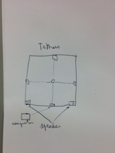
– In case no kinect are available we could use tethers: thanks to them it is possible to determine the position of the dancer and  their movements. However, the dancers would have to be attached to physical objects on stage which is not as practical, but could create interesting performance possibilities
– Flex sensors with an Arduino can also be used as well, though seem more difficult.

Sketches

sk1sk2

Lab 1 – DigiSketch

Group 10:

  • Junjun Chen (junjunc),
  • Igor Zabukovec (iz),
  •  (av),
  • Osman Khwaja (okhwaja).

Description: 

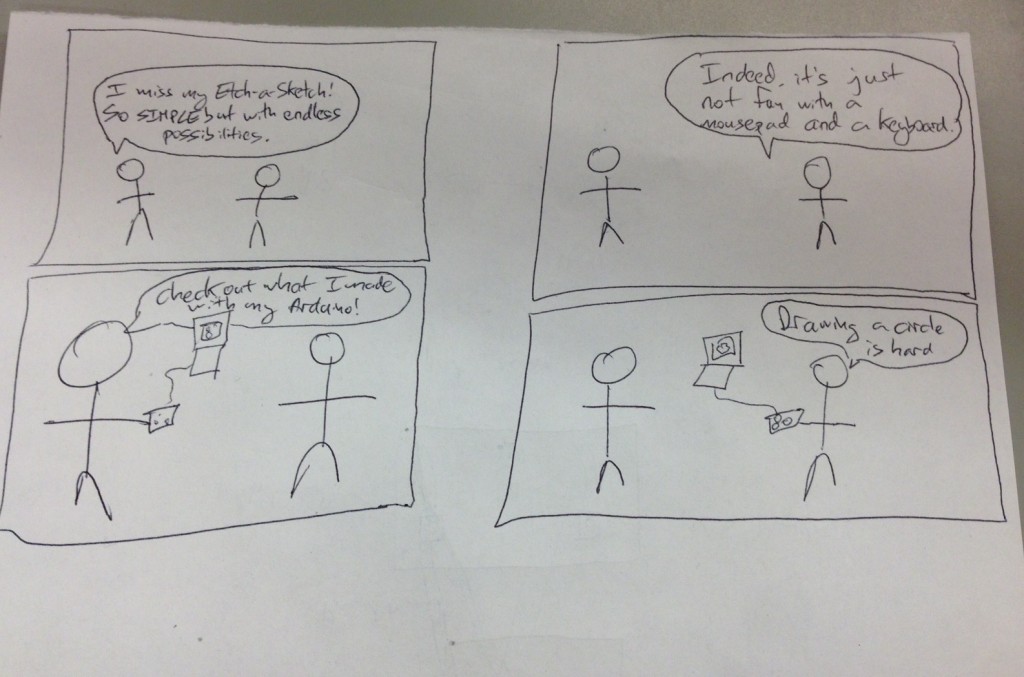
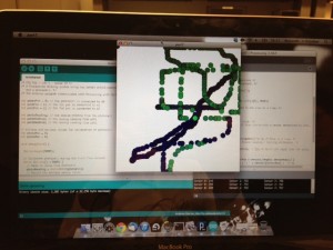
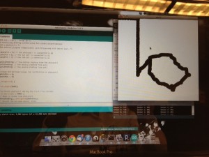
This DigiSketch is intend to do renew the famous Etch-a-Sketch, providing a new way to write on the computer. The principle is quite simple : use the two potentiometers to draw lines of circles and the photo-sensor to change the color of them. You can basically write and draw whatever you want. Start by writing letters, basic forms, and continue by increasing the complexity of your drawings and to test how skillful you are, try to draw a circle. If the user is adventurous, the Processing program can be modified in order to use a different color palette, a different sized canvas, or a different pen shape.

Our system overall achieved its goal. However, the calibration of the photocell could be improved, in order to allow the user more precise control over the color. Perhaps a different sensor could be used for this purpose. To make the system more sophisticated, we could have three different sensors controlling red/green/blue, rather than a single sensor controlling the shade of one color, as we have now. In general, our system proves how easy it is to replicate the Etch-a-Sketch concept; the possibilities for refinement are vast.

Pho­tos of sketches:

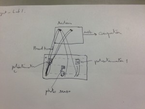
A system which allows you to draw in Processing using two rotary potentiometers to control  position, and using a photocell to control color.

photo2

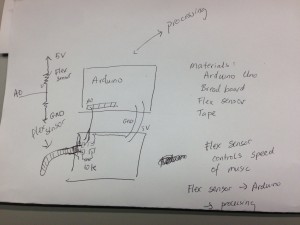
A system which allows you to control the playback speed of a sound file by flexing your finger.

photo

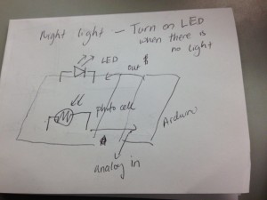
An LED night-light system: turns on the night light when it is dark.

photo3

Sto­ry­board: photo

DigiSketch in Action:

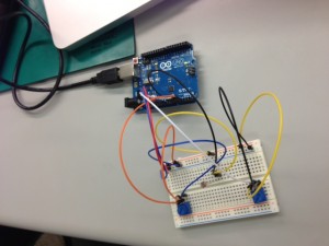
The Arduino and the circuit:

photo7

An example of different colors that can be obtained by varying input to the photocell:

photo6

An attempt at drawing a circle:

photo5

List of parts

  • Arduino, wires, USB cord, breadboard
  • 10 k ohm resistor
  • Photocell
  • 2 rotary pots

Instruc­tions for Recreation

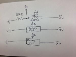
Connect a photocell to the bread board, with a 10kOhm pull down resistor from one leg of the photocell the ground. Connect the other leg to 5V. Connect the point between the photocell and the resistor to analog pin on the Arduino (we used A0). Connect a rotary potentiometer the the breadboard so that one other pin is connected to 5V and the other outer pin is connected to ground. Connect the middle pin to another analog pin (A1). Do the same for the other rotary pot to connect it to A2. Use the attached source code for Processing and Arduino – the Processing program receives messages from Arduino in order to draw on the screen.

Circuit diagram:

photo4

Arduino Source Code:

/* COS 436 - Lab 1 - Group 10 */
/* A Processing drawing system using two rotary potentiometers
   and a photocell. */
/* The Arduino program communicates with Processing with Serial port. */

int photoPin = 0; // the photocell is connected to A0
int pot1Pin = 1; // the 1st pot is connected to A1
int pot2Pin = 2; // the 2nd pot is connected to A2

int photoReading; // the analog reading from the photocell
int pot1Reading; // the analog reading from pot1
int pot2Reading; // the analog reading from pot2

// minimum and maximum values for calibration of photocell
int photoMin = 0;
int photoMax = 0;

void setup(void) {

  Serial.begin(9600);

  // Calibrate photocell during the first five seconds
  while (millis() < 5000) {     // Read in value from photocell     photoReading = analogRead(photoPin);     // Record the maximum sensor value     if (photoReading > photoMax) {
      photoMax = photoReading;
    }
    // Record the minimum sensor value
    if (photoReading < photoMin) {       photoMin = photoReading;     }   }      // Establish contact with Processing   establishContact(); } void loop(void) {   // Only send messages when there is a connection   if (Serial.available() > 0) {
    // Read input from Arduino's analog pins
    photoReading = analogRead(photoPin);
    pot1Reading = analogRead(pot1Pin);
    pot2Reading = analogRead(pot2Pin);

    // Map sensor value to desired range
    photoReading = map(photoReading, photoMin, photoMax, 0, 255);
    photoReading = constrain(photoReading, 0, 255);

    // Send sensor reading as comma separated values.
    Serial.print(photoReading);
    Serial.print(",");
    Serial.print(pot1Reading);
    Serial.print(",");
    Serial.println(pot2Reading);
  }
}

// Establish contact with processing.
void establishContact() {
  // Send an initial string until connection made
  while (Serial.available() <= 0) {
    Serial.println("0,0,0");  
    delay(300);
  }
}
Processing Source Code:
/* COS 436 - Lab 1 - Group 10 */
/* The Processing program recieves input from sensors which the 
   Arduino sends by serial port. */

import processing.serial.* ;

/* Serial port for message communication. */
Serial port;

/* Drawing parameters */
float ypos;
float xpos;
float fgcolor;

void setup() {
  size(500, 500); /* Canvas dimensions */
  background(255); /* White background. */

  println("Available serial ports:");
  println(Serial.list());

  port = new Serial(this, Serial.list()[0], 9600);  

  port.bufferUntil('\n'); /* Read in one line at a time. */
}

void draw() {  
  fill(fgcolor, fgcolor, fgcolor); /* Set color. */
  ellipse(xpos, ypos, 20, 20); /* Draw circle with a center determined by pots. */
}

void serialEvent(Serial port) {
  String myString = port.readStringUntil('\n'); /* Read in a line. */
  myString = trim(myString); /* Remove leading / tailing whitespace. */

  int sensors[] = int(split(myString, ',')); /* Split CSV input into int array. */

  // Print out sensor values:
  for (int sensorNum = 0; sensorNum < sensors.length; sensorNum++) {     print("Sensor " + sensorNum + ": " + sensors[sensorNum] + "\t");   }   println();      if (sensors.length > 1) { /* else input is incorrectly formatted */
    fgcolor = 255 - sensors[0]; /* Set color of circles */
    xpos = map(sensors[1], 0, 1023, 0, width); /* Set x-position of circle center. */
    ypos = map(sensors[2], 0, 1023, 0, height); /* Set y-position of circle center. */
  }
  port.write("A"); // Send byte to get more data from Arduino program.
}

Lab 0: RGB Whack-a-Mole


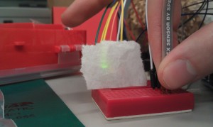
We designed an RGB version of the ever-popular Whack-a-Mole game using a single multicolor LED, some buttons, and good old Arduino. We wanted to create something entertaining and interactive, that similarly allowed us to explore coding on the Arduino. At first, we envisioned a game with multiple LED’s, but then decided that playing the game in response to different colors in a single light was much more interesting than responding to the turning on or off of lights. Our second revision imagined the multicolor LED starting out as fully lit (white light), and then having components of the light drop out with the player having to press buttons to restore those color components. We liked the dual challenge both of reacting quickly and having to determine which color component was missing, but when playtesting we found that this latter aspect of the challenge was more frustrating than enjoyable for the player. Our final version lights up the LED with one of the three colors behind the diffusion screen and rapidly begins to dim. If the player either fails to respond in time or presses the wrong button, the light will go white, signaling GAME OVER! We are overall quite happy with how the game turned out, and how it helped us play around with the Arduino. The game is fun and completely customizable in just about every parameter. However, we had very few materials with which to construct the physical exterior of the game, so the prototype itself is somewhat of an eyesore.

Team Members: Joseph Bolling, Evan Strasnick, Aleksey Boyko, Jacob Simon

List of Parts:

  • Arduino Uno
  • Pushbutton style switches (3)
  • Tri-color RGB LED
  • 330Ω resistors (3)
  • Wire jumpers
  • Prototyping Breadboards (2)
  • Cardboard
  • Scotch tape

Instructions:

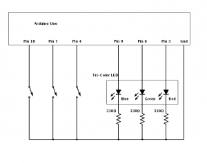
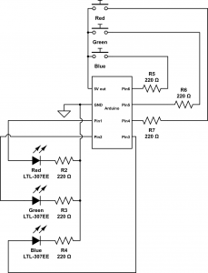
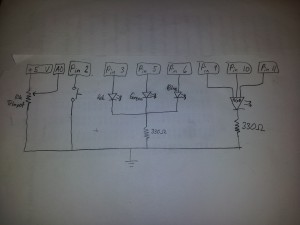
To create your own RGB Whack-a-Mole game, take a look at the circuit included above as a reference.  For the switches, use basic push-buttons.  Note that we chose to place our buttons on a separate breadboard from our tri-color LED, so that we would have a rudimentary controller and output device setup.  Connect the button that you’d like to correspond to the red color to pin 4 of the Arduino, the button that you’d like to use for blue to pin 7, and the button that you’d like to use for green to pin 10.  The red, green, and blue led leads should connect to pins 3, 6, and 9, respectively.

Label your buttons with the color they control, and make a cover for your LED so that the wiring is protected and hidden.  We used simple cardboard and some scotch-tape to make a window for our LED.  Then, upload our code to your Arduino and have fun!

Diagrams:

RGB Whack-a-Mole Circuit — This is the idea we implemented.

WhackAMole

Binary Calculator Circuit — This would allow the user to perform simple arithmetic.

BinaryCalculator

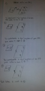
Color Selector Circuit — This would allow the user to create any color by selecting its RGB components.

Sketch 3 - Color scaler

Arduino Program:

// :::::::::::::::::::::::
// Lab 0
// COS436 / ELE469
// Trichromatic Whack-a-Mole / Color Blindness Reflex Test
// Group participants: jbolling, jasimon, estrasni, aboyko
// :::::::::::::::::::::::

// :::::::::::::::::::::::
// INPUT PINS
// :::::::::::::::::::::::
int r_but = 4;
int g_but = 7;
int b_but = 10;

// :::::::::::::::::::::::
// OUTPUT PINS
// :::::::::::::::::::::::
int r_pin = 3;
int g_pin = 6;
int b_pin = 9;

// :::::::::::::::::::::::
// INITIAL COLOR VALUES
// :::::::::::::::::::::::
int r_v = 0;
int g_v = 0;
int b_v = 0;

// :::::::::::::::::::::::
// DIMMING PARAMETERS
// :::::::::::::::::::::::
boolean dim_on = false;
int dim_delta = 0;
float dim_factor = 1;
int dim_ch = 0;
int counter = 1;
int score = 0;

// :::::::::::::::::::::::
// SETUP FUNCTION
// :::::::::::::::::::::::
void setup() {

Serial.begin(9600); // Terminal output

// Input settings
pinMode(r_but, INPUT);
pinMode(g_but, INPUT);
pinMode(b_but, INPUT);

digitalWrite(r_but, HIGH);
digitalWrite(g_but, HIGH);
digitalWrite(b_but, HIGH);

// Output settings
pinMode(r_pin, OUTPUT);
pinMode(g_pin, OUTPUT);
pinMode(b_pin, OUTPUT);

Serial.println(“Set up complete”);

reset_state();

}

// :::::::::::::::::::::::
// MAIN LOOP
// :::::::::::::::::::::::
void loop() {
// If no dimming is happening, try to initiate
if (!dim_on) {
Serial.println(“Dim is not on”);
dim_on = initiate_dimming();
}

int io_code = factor_input();
if (dim_on) {
Serial.println(“Dim is on!”);

// see if input stops dimming
if (io_code != 0) {
// no user input
dim_more();
} else {
// correct input
counter++;
reset_state();
}
} else {
reset_state();
}

// set the diffuser output
analogWrite(r_pin, r_v);
analogWrite(g_pin, g_v);
analogWrite(b_pin, b_v);

delay(100);
}

void reset_state() {

// Reset color values
r_v = 0;
g_v = 0;
b_v = 0;

// Turn dimming off
dim_ch = 0;
dim_on = false;
}

boolean initiate_dimming() {

// Choose a random color
dim_ch = random(0, 3);

// Turn that color on, full brightness
switch (dim_ch) {
case 0:
analogWrite(r_pin, 255);
r_v = 255;
break;
case 1:
analogWrite(g_pin, 255);
g_v = 255;
break;
case 2:
analogWrite(b_pin, 255);
b_v = 255;
break;
default:
break;
}

// New dimming factor
dim_factor = 1.0 – (counter) / 20.0;

// Terminal output
Serial.print(“\tDimming channel “);
Serial.print(dim_ch);
Serial.print(” with factor “);
Serial.println(dim_factor);

return true;
}

int factor_input() {

// read KEY_DOWN events
boolean r_pressed = (digitalRead(r_but) == LOW);
boolean g_pressed = (digitalRead(g_but) == LOW);
boolean b_pressed = (digitalRead(b_but) == LOW);
// encode input with one value
int in_code = (r_pressed?1:0) + (g_pressed?2:0) + (b_pressed?4:0);

// if any was down wait until all keys are released
while (r_pressed || g_pressed || b_pressed) {
delay(100);
r_pressed = (digitalRead(r_but) == LOW);
g_pressed = (digitalRead(g_but) == LOW);
b_pressed = (digitalRead(b_but) == LOW);
}

// Encode dimming channel in the same way as buttons
int out_code = 0;
if (dim_on)
out_code = 1 << dim_ch;

// Difference between input and output
int input_factor = out_code – in_code;

// If user’s input doesn’t match correct input…
if (input_factor != 0 && in_code != 0) {
failure(); // Fail and reset
}

return input_factor;
}

void dim_more() {
if (!dim_on) return;

switch(dim_ch) {
case 0:
//r_v += dim_delta;
r_v *= dim_factor;
if (r_v < 10) failure();
break;
case 1:
//g_v += dim_delta;
g_v *= dim_factor;
if (g_v < 10) failure();
break;
case 2:
//b_v += dim_delta;
b_v *= dim_factor;
if (b_v < 10) failure();
break;
default:
break;

}

}
void failure() {
digitalWrite(r_pin, 255);
digitalWrite(g_pin, 255);
digitalWrite(b_pin, 255);
Serial.print(“Game over! Score = “);
Serial.print(score);
Serial.println(” Try again…?”);
score = 0;
counter = 1;
dim_on = false;
delay(3000);
}

void light_correct() {
score++;
reset_state();
}

Harlem Shake v436

Group Members

Osman Khwaja
Alejandro Van Zandt-Escobar
Gabriel Chen
Avneesh Sarwate
Prakhar Agarwal

Description

We built a glass world that reacts to light using a photosensor and behaves according to the state it is in. There are three states governed by a button: the idle state, the build state, and the drop state. Before the button is enabled, the world is in a calibration state, used to expose the photoresistor to the range of possible light inputs and thus, resistances. The idle state consists of a tricolor LED, fitted with a straw. The tricolor LED oscillates between all ranges of colors according to three sin functions. The other LEDs do nothing. The build state is to be initiated by the press of the button when the song “Harlem Shake” is played (in light of the recent trend). The tricolor LED begins to change colors erratically, and the remaining LEDs alternate slowly between reds and blues, arranged diagonally from each other. The behavior matches the tempo of the song. The drop state is to be initiated at the beat drop of the song. The tricolor LED continues its erratic behavior, but the remaining LEDs now act based on the light sensor. This can be used to induce extremely erratic behavior all LEDs, in accordance with Harlem Shake tradition. Thus, we felt that our design successfully produced the desired behavior. The different states of the design are a good representation of different stages in the song, and the use of a button allows for ease of state transition. Additionally, the straw and ice cube trays were excellent diffusers, and really emphasized the output of the LEDs. One limitation of our design was the sensitivity of the photoresistor. It was placed under a thick layer of glass, which may have diffused light entering the circuit. Although this made the design more aesthetic, the functionality was slightly impaired. Overall, we were happy with the Harlem Shake video we were able to produce using our design, and we hope that it goes viral!

Photos of Sketches

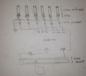
Slide sensor controls the brightness of the lights. Lights closest to finger are brightest. Move finger to control the light.

Follow the finger: Slide sensor controls the brightness of the lights. Lights closest to finger are brightest. Move finger to control the light.


Perfect Pushup - Use a diffuser and flex sensor to determine whether pushup form is correct or not.

Perfect Pushup: Use a diffuser and flex sensor to determine whether pushup form is correct or not.


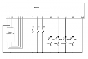
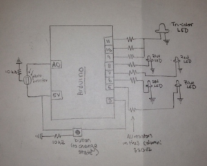
A schematic of our final design.

A schematic of our final design.


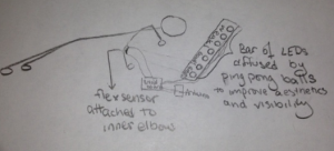
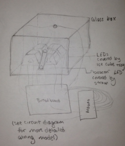
A design diagram of our project

A design diagram of our project.

Video

Parts

  • Arduino Uno
  • Button
  • Photoelectric Sensor
  • Ice Cube Tray
  • Glass Box/Flower Vase
  • 1 Straw
  • Wires
  • 2 10k Ohm Resistor
  • 7 330 Ohm Resistors
  • 2 Blue LEDs
  • 2 Red LEDs
  • 1 Tricolor LED
  • 2 Alligator Clips
  • Tape

Instructions

  1. Connect the TriColor LED to the three analog pins 11, 10, 9 through 330 Ohm resistors.
  2. Connect 4 LEDs in a general box shape just below the TriColor to the pins 7,6,5,4 with a 330 Ohm Resistor for each.
  3. Attach a photoelectric sensor to the top of the glass box using the alligator clips. Ensure that the sensor is facing outwards.
  4. Connect the button to the breadboard with the 10k Resistor, pulling 5 Volts from Arduino. Connect the output to pin 3.
  5. Connect the photosensor with a 10k Resistor to pin A0 on the Arduino.
  6. Cover the 4 LEDs with the ice cube tray, the tricolor with a straw, and all of them with the glass case.
  7. When powering up the system, make sure to calibrate the photosensor by covering and uncovering the sensor. The Blue LED will light up during this time.

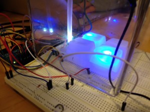
    Here is what the final setup should look like.

    Here is what the final setup should look like.

Source Code

// ----------------------
// Harlem Shake v. 436
// ----------------------
// COS 436, Lab 0
// February 18, 2013
// ----------------------
// Prakhar Agarwal
// Gabriel Chen
// Osman Khwaja
// Avneesh Sarwate
// Alejandro Van Zandt-Escobar
// ----------------------
// The "beacon" (multicolor LED) is connected to three analog outputs
const int beaconRed = 11;
const int beaconGreen = 10;
const int beaconBlue = 9;
// The four other LEDs are connected to four digital outputs
const int ledYellow = 8;
const int ledRed = 7;
const int ledBlue = 6;
const int ledGreen = 5;

// Sensor 1: Photocell
const int sensorPin = A0;

int sensorValue = 0;
int sensorMin = 1023; // minimum sensor value
int sensorMax = 0; // maximum sensor value
int threshold = 127;

// Button
const int buttonPin = 3;

int buttonState = 0; // HIGH or LOW
int buttonCounter = 0; // Number of clicks determines the program's current state.
int lastButtonState = 0; // HIGH or LOW

// Setup Routine
void setup() {

// For debugging:
Serial.begin(9600);

// Set up I/O.
pinMode(beaconRed, OUTPUT);
pinMode(beaconGreen, OUTPUT);
pinMode(beaconBlue, OUTPUT);

pinMode(ledGreen, OUTPUT);
pinMode(ledBlue, OUTPUT);
pinMode(ledRed, OUTPUT);
pinMode(ledYellow, OUTPUT);

pinMode(buttonPin, INPUT);

// Calibrate photocell during the first five seconds.
while (millis() < 5000) { // Light up LED at the beginning of calibration phase. digitalWrite(ledBlue, HIGH); // Read in value from photocell sensorValue = analogRead(sensorPin); // Record the maximum sensor value if (sensorValue > sensorMax) {
sensorMax = sensorValue;
}

// Record the minimum sensor value
if (sensorValue < sensorMin) {
sensorMin = sensorValue;
}

// Turn off LED at end of calibration phase
digitalWrite(ledBlue, LOW);

}

}

// Variables for timing and rhythm
double time = 0;
double t = 0; // Used for sin wave patterns
int beat = 430; // Duration of a beat (in ms)
int downBeatBeacon;
int downBeatCubes;

void loop() {

// *** Process Photocell Input ***
// Read photocell sensor
sensorValue = analogRead(sensorPin);
// Apply calibration
sensorValue = map(sensorValue, sensorMin, sensorMax, 0, 255);
// Map sensor value to desired range
sensorValue = constrain(sensorValue, 0, 255);

// *** Process Button Input ***
// Read state of pushbotton
buttonState = digitalRead(buttonPin);
// Compare the buttonState to its previous state
if (buttonState != lastButtonState) {
// State changes when button is pressed down (from off to on)
// If state has changed then increment counter
if (buttonState == HIGH) {
// If the current state is HIGH then button went from off to on
if (buttonCounter == 2)
buttonCounter = 0;
else
buttonCounter++;
// For debugging:
// Serial.println("on");
// Serial.print("number of button pushes: ");
// Serial.println(buttonCounter);
}
else {
// If the current state is LOW then the button went from on to off
Serial.println("off");
}
}
// save the current state as the last state, for next time through the loop
lastButtonState = buttonState;

// *** Main Program Loop ***

// *** Idle State ***
if (buttonCounter == 0) {
// Tri-color LED has an intersecting sinusoidal pattern
analogWrite(beaconRed, (int) (127 + 127 * sin(t)));
analogWrite(beaconBlue, (int) (127 + 127 * sin(t + 3.14/3)));
analogWrite(beaconGreen, (int) (127 + 127 * sin(t + 6.28/3)));

// Turn all other LEDs off
digitalWrite(ledBlue, LOW);
digitalWrite(ledGreen, LOW);
digitalWrite(ledRed, LOW);
digitalWrite(ledYellow, LOW);

// Progression of sinusoidal pattern
t += 0.1;
delay(20);
}

// *** Build State ***
else if (buttonCounter == 1) {
// Beacon's activity is determined by eighth notes
downBeatBeacon = ((int) (time / (beat / 2)));
// Cube's activity is determined by half notes
downBeatCubes = ((int) (time / (beat * 2))) % 2;

// The beacon plays an accelerated sinusoiodal pattern
// Erratically matched to the rhythm of eighth notes
analogWrite(beaconRed, (int) (127 + 127 * sin(downBeatBeacon + .9)));
analogWrite(beaconBlue, (int) (127 + 127 * sin(9 * downBeatBeacon + .2)));
analogWrite(beaconGreen, (int) (127 + 127 * sin(7 *downBeatBeacon)));

// The four LEDs in the icecube alternate diagonally, on every half beat.
// On beat 1:
if (downBeatCubes == 0) {
digitalWrite(ledBlue, HIGH);
digitalWrite(ledGreen, LOW);
digitalWrite(ledRed, LOW);
digitalWrite(ledYellow, HIGH);
}
// On beat 2:
else if (downBeatCubes == 1) {
digitalWrite(ledBlue, LOW);
digitalWrite(ledGreen, HIGH);
digitalWrite(ledRed, HIGH);
digitalWrite(ledYellow, LOW);
}

// Update every eighth note
delay(beat / 2);
time += beat / 2;

}

// *** Drop State ***
else {
// Beacon's activity is determined by eighth notes
downBeatBeacon = ((int) (time / (beat / 2)));

// The beacon plays an accelerated sinusoiodal pattern
// Erratically matched to the rhythm of eighth notes
analogWrite(beaconRed, (int) (127 + 127 * sin(downBeatBeacon + .9))); // turn the LED on (HIGH is the voltage level)
analogWrite(beaconBlue, (int) (127 + 127 * sin(9 * downBeatBeacon + .2))); // turn the LED on (HIGH is the voltage level)
analogWrite(beaconGreen, (int) (127 + 127 * sin(7 *downBeatBeacon)));

// The cube LEDs play the same pattern, but switch according
// to input from the photocell.
if (sensorValue < threshold) {
digitalWrite(ledBlue, HIGH);
digitalWrite(ledGreen, LOW);
digitalWrite(ledRed, LOW);
digitalWrite(ledYellow, HIGH);
}
else {
digitalWrite(ledBlue, LOW);
digitalWrite(ledGreen, HIGH);
digitalWrite(ledRed, HIGH);
digitalWrite(ledYellow, LOW);
}

// Update every eighth note
delay(beat / 2);
time += beat / 2;
}
}

Color Mixer

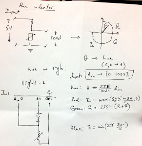
i. Group: Philip Oasis, Gene Merewether, Alice Fuller, Rodrigo Menezes

ii. We built a color mixer, in which the user turns a potentiometer to adjust the brightness of red, green, and blue LEDs, and then observes the mixed output of the three hues on a single RGB LED.  The purpose for the user is to observe how RGB colors are mixed, as well as a fun way to try making new colors.  The tissue paper diffuser is meant to spread out the light and make it easier to view.  We feel that it is successful in achieving these goals, and that the interface is relatively easy to understand and operate.  We enjoyed using the final product and trying to make interesting colors.  We might have liked to use more LED’s to make the panel brighter and easier to see.

iii. Sketches of possible designs
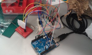
20130213_201102

A reaction game where the user tries to hit the push button after the final LED is lit.

rgb-two-step-memory-game


A memory game in which the user uses a button to select the LED which was lit a certain number of lights ago.

20130206_210759 20130206_220008


A color mixer in which the user selects brightness of red, green, and blue LED’s and then observes the combination of those hues.

iv. Video of the system in action

http://www.youtube.com/watch?v=RQmMFz5ngmM

v. Parts list

  • (1) Red LED
  • (1) Green LED
  • (1) Blue LED
  • (1) Tricolor LED
  • (1) 10k trimpot
  • (4) 330 ohm resistor
  • (2) Breadboard

vi. Instructions to recreate design

  1. Connect potentiometer to analog pin A0, powered by 5v
  2. Connect push button to digital pin 2, powered by 5v, with a 330Ω resistor.
  3. Connect red, green, and blue LED’s to digital pins 3, 5, and 6 (respectively), all powered by 5v and each with a 330Ω resistor.
  4. Connect the rgb LED to digital pins 9, 10, and 11, again powered by 5v, and with 330Ω resistors.
  5. (optional) Cover the LED’s with a tissue paper diffuser

vii. Source code

const int sensorPin = 0;
const int buttonPin = 2;
const int redPin = 3;
const int greenPin = 5;
const int bluePin = 6;
const int ledRedPin = 9;
const int ledGreenPin = 10;
const int ledBluePin = 11;
 
const int RED_STATE = 0;
const int GREEN_STATE = 1;
onst int BLUE_STATE = 2;
 
int prevButtonState;
int systemState;
int redValue;
int greenValue;
int blueValue;
void setup() {
    Serial.begin(9600);
    pinMode(buttonPin, INPUT);
    pinMode(redPin, OUTPUT);
    pinMode(bluePin, OUTPUT);
    pinMode(greenPin, OUTPUT);
    pinMode(ledRedPin, OUTPUT);
    pinMode(ledGreenPin, OUTPUT);
    pinMode(ledBluePin, OUTPUT);
 
    prevButtonState = HIGH;
    systemState = RED_STATE;
    redValue = 0;
    greenValue = 0;
    blueValue = 0;
}
 
void loop() {
    int buttonState = digitalRead(buttonPin);
    int sensorValue = analogRead(sensorPin)/4;
    Serial.println(sensorValue);
 
    if (buttonState == HIGH && prevButtonState == LOW)
    {
        systemState = systemState + 1;
        if (systemState == 3)
        {
            systemState = 0;
        }

    }
    prevButtonState = buttonState;
    switch (systemState)
    {
         case RED_STATE:
             redValue = sensorValue;
             analogWrite(redPin, redValue);
             analogWrite(greenPin, 0);
             analogWrite(bluePin, 0);
             break;
         case GREEN_STATE:
             greenValue = sensorValue;
             analogWrite(redPin, 0);
             analogWrite(greenPin, greenValue);
             analogWrite(bluePin, 0);
             break;
         case BLUE_STATE:
             blueValue = sensorValue;
             analogWrite(redPin, 0);
             analogWrite(greenPin, 0);
             analogWrite(bluePin, blueValue);
             break;
         }

analogWrite(ledRedPin, redValue);
analogWrite(ledGreenPin, greenValue); 
analogWrite(ledBluePin, blueValue); 
} 

Strength Testing Game

Group Members

Jeff Snyder (jasnyder@)
Clay Whetung (cwhetung@)
Michael Newman (menewman@)
Neil Chatterjee (neilc@)

Description

We built a “strongman game” that uses a flex sensor to measure a player’s “digital” strength. As the player flexes the sensor, the amount of flex is categorized into one of five strength levels, and we use three LEDs and a speaker to demonstrate which level has been reached. Within each level, the brightness of the brawniest LED reached is varied with pulse-width modulation to match the player’s exertions. At the lowest level, none of the LEDs are lit and the speaker produces no noise. At the next-lowest level, the green LED lights up. At the middle level, the green and yellow LEDs light up. At the second-highest strength level, the green, yellow, and red LEDs light up. At max strength, all three LEDs light up and celebratory music plays from the speaker. We chose to build this because we wanted a way to demonstrate our finger-flexing prowess, and the game’s cheerful blinking lights and victory song brightened our day while affirming our digital swole. In general, the project was a success, and we were especially pleased with the jingle. For future improvement we might want to change the kind of sensor being used (for example, a pressure sensor that measures the force from the strike of a comically large hammer) and/or the number of lights and tunes available (and consequently, the number of strength categories available).

Video

Arduino Strength Tester

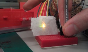
Each Strength Level

First Strength Level

Strength Level One

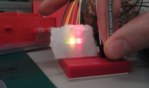
Second Strength Level

Strength Level Two

Third Strength Level

Strength Level Three


Design Sketches and Final Build
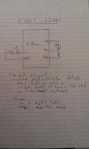
Night Light

First Design – Night Light

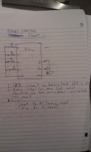
Clapping Binary Counter

Second Design – Clapping Binary Counter

Strength Tester

Third Design – Strength Tester

Strength Tester

Final Strength Tester Design


Parts Used

– 3 LEDS (green, yellow, red)
– 1 speaker
– 1 flex resistor
– 1 Arduino
– jumper wires
– 2 breadboards
– 3 330-ohm resistors
– 1 100-ohm resistor
– 1 10k-ohm resistor
– 1 laptop with usb cable
– 1 wax paper diffuser

Instructions

1. Set up the LEDs in a line on a breadboard next to the flex sensor. Place the speaker across the center divider of the other breadboard. You may find it helpful to connect ground and +5V to the power rails of the breadboard for the following steps.

2. Make the following connections:
– Connect the anode of the red LED to pin 6 of the Arduino, the anode of the yellow LED to pin 11, and the anode of the green LED to pin 11.
– Connect the cathode of each LED to ground via a 330 ohm resistor.
– Connect one pin of the speaker to pin 8 and the other to ground via a 100 ohm resistor.
– Connect one side of the flex sensor to a +5V pin.
– Connect the other side both to A0 and to ground via a 10 kilo-ohm resistor.

3. Check the values output by the flex sensor using the serial monitor and the Serial.println() function. In the code, change the FLEX_MAX and FLEX_MIN values as appropriate.

4. Mount the wax paper diffuser in front of the three LEDs.

5. Test your brawn!

Source Code

/* 
  Authors: jasnyder, cwhetung, menewman, neilc
  Date: 2/11/2013
  COS 436 Lab L0: The Strength Test

  Test the user's strength with a flex sensor. Display the
  results to LEDs and play them a tune if they are truly
  powerful.
*/
#include "pitches.h"

const int FALSE = 0;
const int TRUE = 1;

//  Input / Output Constants
const int FLEX_MIN = 150;  //  set me as appropriate!
const int FLEX_MAX = 348;  //  set me as appropriate!
const int NUM_STAGES = 6;
const int STAGE_SIZE = ((FLEX_MAX - FLEX_MIN) / NUM_STAGES);
const int ANALOG_MAX = 255;

//  Possible States
const int SONG = 0;
const int ALL_ON = 1;
const int TWO_ON = 2;
const int ONE_ON = 3;
const int ALL_OFF = 4;

//  Musical Constants
const int NOTE_DELAY = 300; // (ms)
const int NOTE_DUR = 250;

//  Pin Connection Constants
const int green = 11;
const int red = 6;
const int yellow = 10;
const int flex = A0;
const int speaker = 8;

//  Variables
int flexvalue = 0;  //  value returned by flex sensor
int stage = 0;  //  current state of LEDs / sensor
int play = 0;  //  have we already played the tune?
int pwmout = 0;  //  dimming value

//  Set internal pull-ups for output on LED pins
void setup()
{
  pinMode(green, OUTPUT);
  pinMode(red, OUTPUT);
  pinMode(yellow, OUTPUT);
}

void loop() {

  //  Grab the bend value and map it to one of the stages
  flexvalue = analogRead(flex);
  stage = map(flexvalue, FLEX_MIN, FLEX_MAX, 0, NUM_STAGES - 1);

  //  Within each stage, dim the "last" LED to the approximate
  //  progression through the stage 
  pwmout = (flexvalue - FLEX_MIN) % STAGE_SIZE;
  pwmout = map(pwmout, 0, STAGE_SIZE, 0, ANALOG_MAX);

  //  Turn all LEDS on and play the song once
  if (stage == SONG) {
    digitalWrite(green, HIGH);
    digitalWrite(yellow, HIGH);
    digitalWrite(red, HIGH);

    //  If we have already played the song, do nothing
    if (play == FALSE)
    {
      playACongratulatoryTune();
      play = TRUE;
    }
  }

  //  All on, red variable
  if (stage == ALL_ON) {
    play = FALSE;  //  reset the song
    digitalWrite(green, HIGH);
    digitalWrite(yellow, HIGH);
    analogWrite(red, pwmout);
  }

  //  Green and yellow on, yellow variable
  if (stage == TWO_ON) {
    play = FALSE;
    digitalWrite(green, HIGH);
    analogWrite(yellow, pwmout);
    digitalWrite(red, LOW);
  }

  //  Green on and variable
  if (stage == ONE_ON) {
    play = FALSE;
    analogWrite(green, pwmout);
    digitalWrite(yellow, LOW);
    digitalWrite(red, LOW); 
  }

  //  All leds off
  if (stage == ALL_OFF) {
    play = FALSE;
    digitalWrite(green, LOW);
    digitalWrite(yellow, LOW);
    digitalWrite(red, LOW); 
  }
}

//  Play a classic little ditty!
void playACongratulatoryTune() {
  tone(speaker, NOTE_G4, NOTE_DUR);
  delay(NOTE_DELAY);
  tone(speaker, NOTE_C5, NOTE_DUR);
  delay(NOTE_DELAY);
  tone(speaker, NOTE_E5, NOTE_DUR);
  delay(NOTE_DELAY);
  tone(speaker, NOTE_G5, NOTE_DUR);
  delay(NOTE_DELAY*2);
  tone(speaker, NOTE_E5, NOTE_DUR);
  delay(NOTE_DELAY);
  tone(speaker, NOTE_G5, NOTE_DUR*4);
  delay(NOTE_DELAY*5); 
}

Uploading Video Files

This blog has been enhanced with the ability to upload videos to the campus Kaltura video management system. This system facilitates the use of video by streamlining the transcoding and streamed delivery of video materials. Streamed videos play much quicker and more smoothly because they do not need to be downloaded before playback can begin.

kaltura-iconTo upload a video from your computer while editing a post or page, click the orange Add Interactive Video icon just above the text entry area.

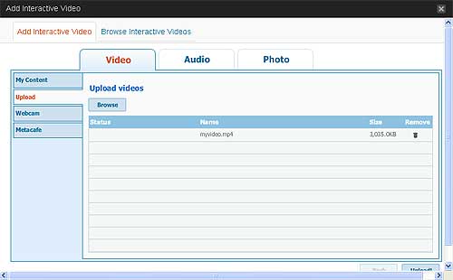
In the resulting window, make sure the Video tab is selected and select Upload from the left-hand menu. Click Browse to navigate to the video file on your computer. Note that you may also select multiple video files if you wish.

upload

After the video files appear in the list, click the Upload button in the bottom-right hand corner of the window.

After the file has finished uploading, click Next to begin the conversion of the file into a format suitable for presentation on the web.

In the next window, you may select any specifics about the design of the player on the page, but the default settings should be fine.

Click Insert into Post to insert the necessary codes into the post and to begin the conversion process.

Don’t forget to click Publish (or Update if you are editing an existing post) to save your post.

Please be aware that the conversion process can take quite a while depending on the size of the video.  When the video has finished processing, it will be available for viewing.