Not just your average crane…

I. Group members:

Xin Yang Yak <xyak@princeton.edu>, Junjun Chen <junjunc@princeton.edu>, Josh Chen <joshchen@princeton.edu>, Igor Zabukovec <iz@princeton.edu>

II. Description:

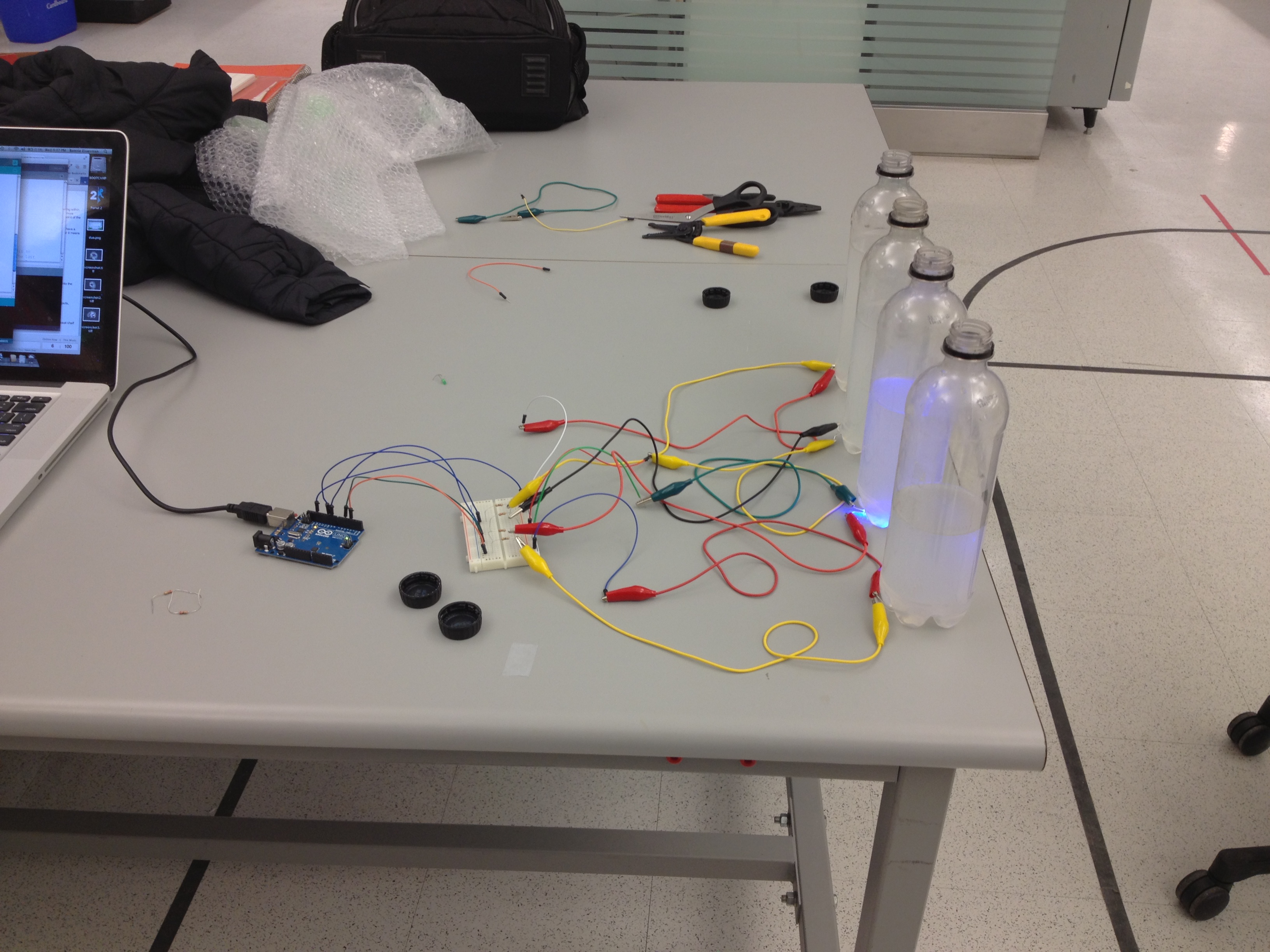
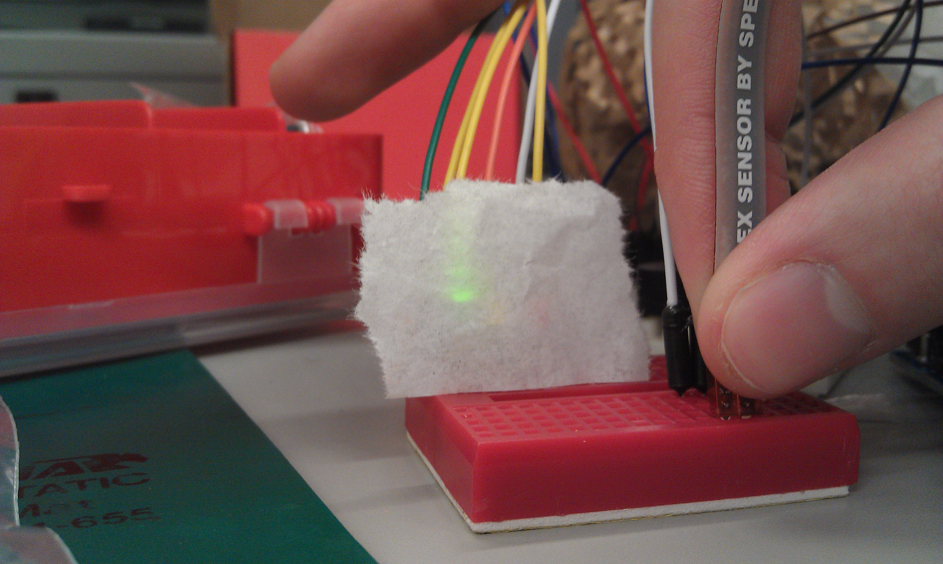
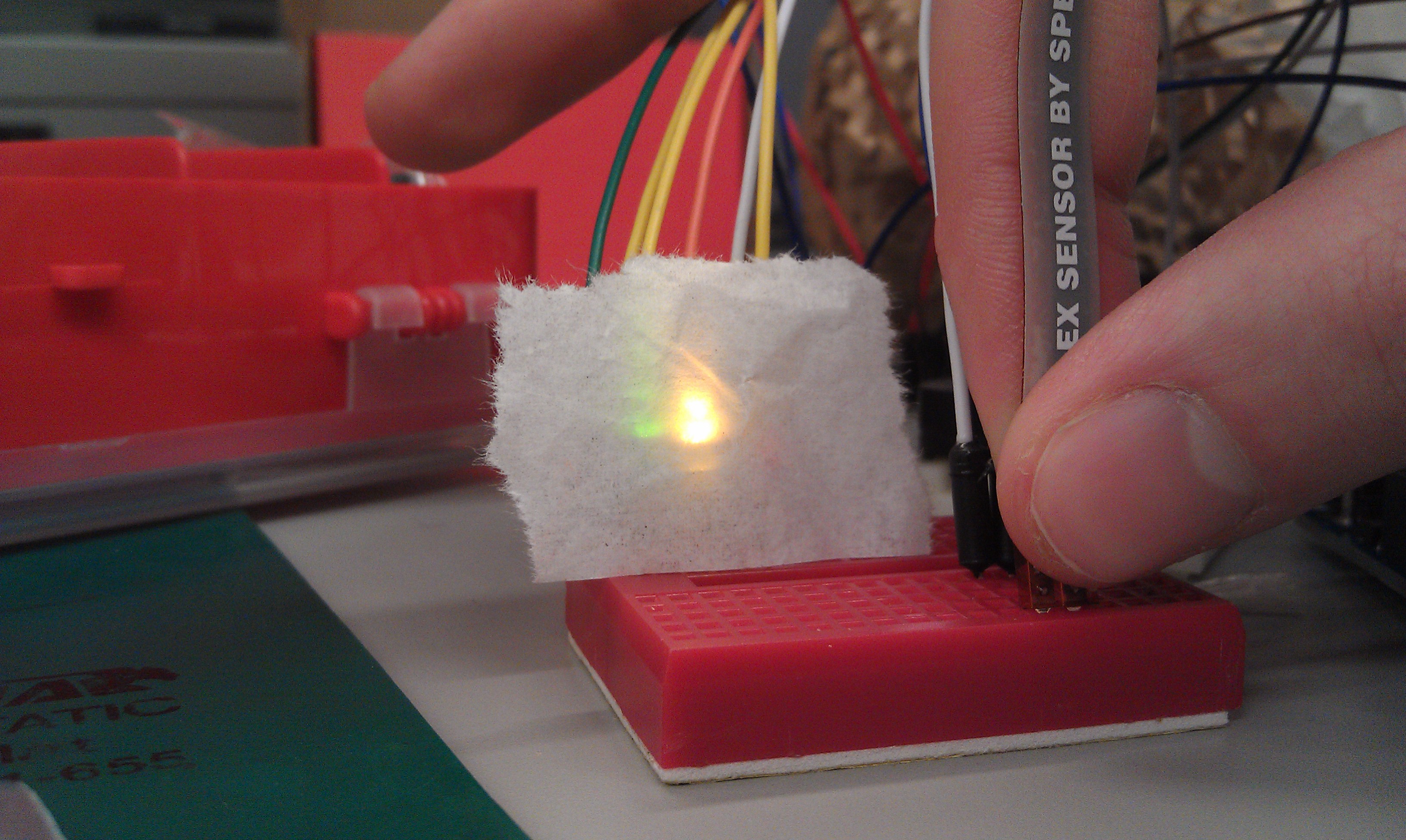
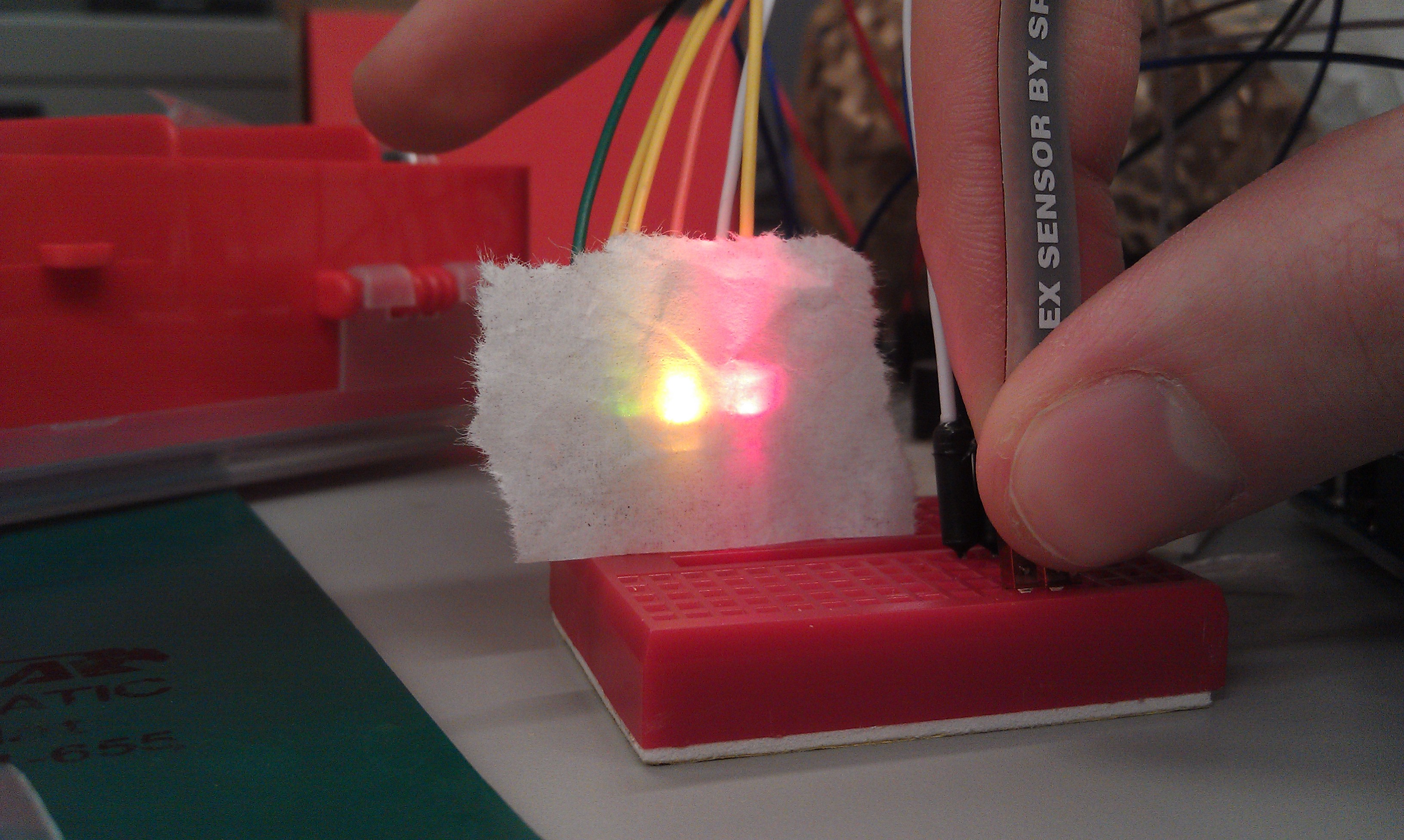
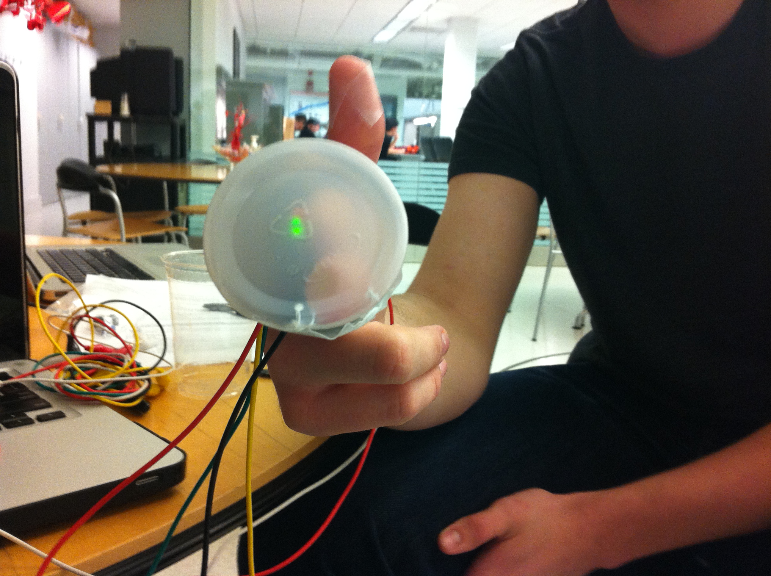
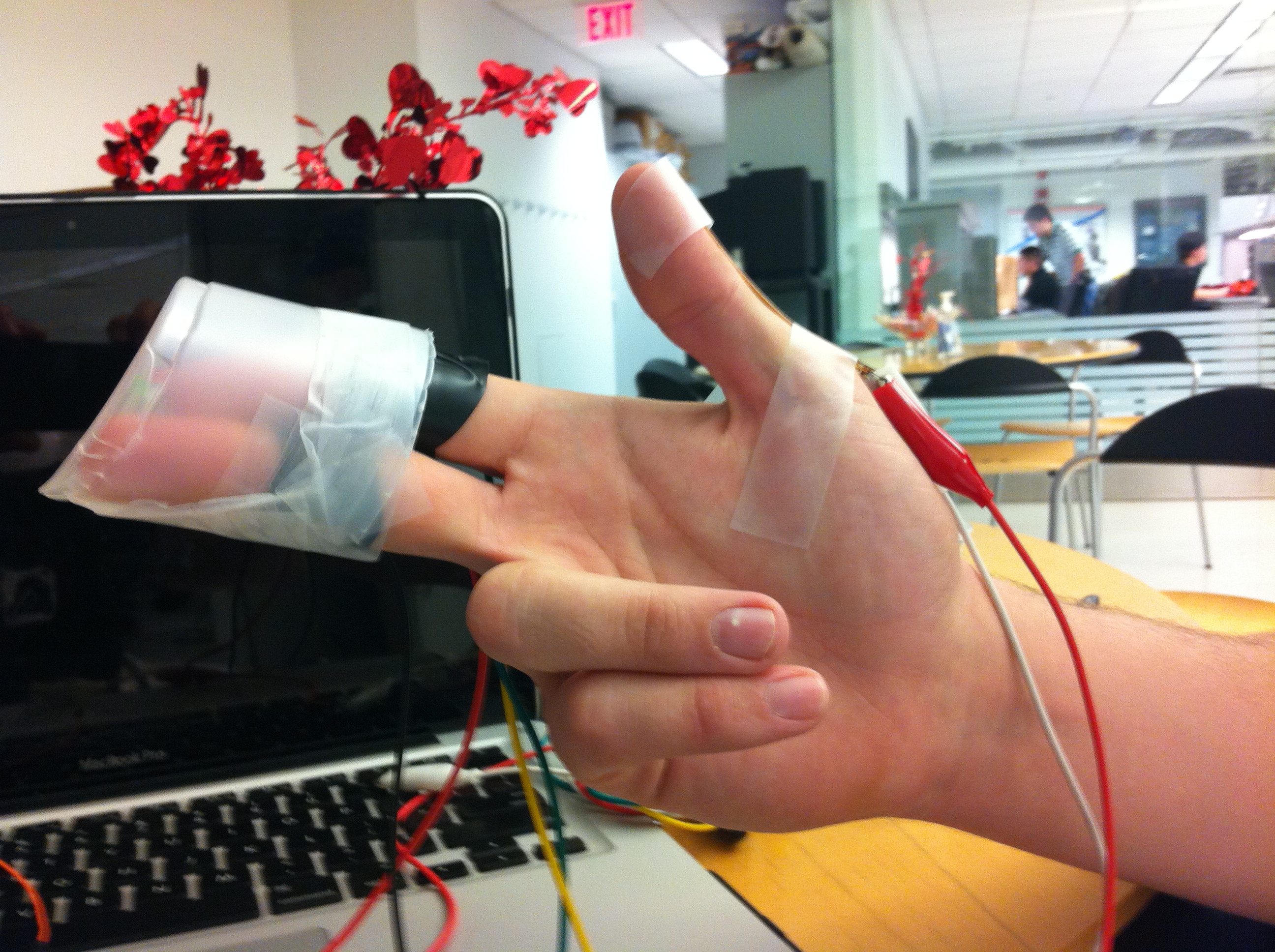
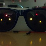
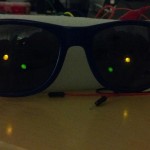
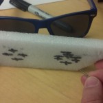
We made an ornamental Origami crane that glows with different colors based on its state. The crane glows red when left alone, and flashes green and blue when its tail is bent in the standard Origami way. We liked this design because it puts multiple forms of interactivity into one design: The crane responds to someone pulling its tail both electronically and mechanically, by both changing color (thanks to the Arduino and Flex sensor) and changing shape (thanks to our Origami design).  We think that our design was successful because, as shown in our video, all intended functionality worked.  However, the Flex sensor is quite visible and fragile, as it is only taped externally onto the crane’s tail.  The design could be improved upon if we had a Flex sensor that was thinner, shorter, and less rigid – ideally, we would use a wire Flex sensor that changed resistance when bent.

III. Diagram:

2013-02-16 16.45.35

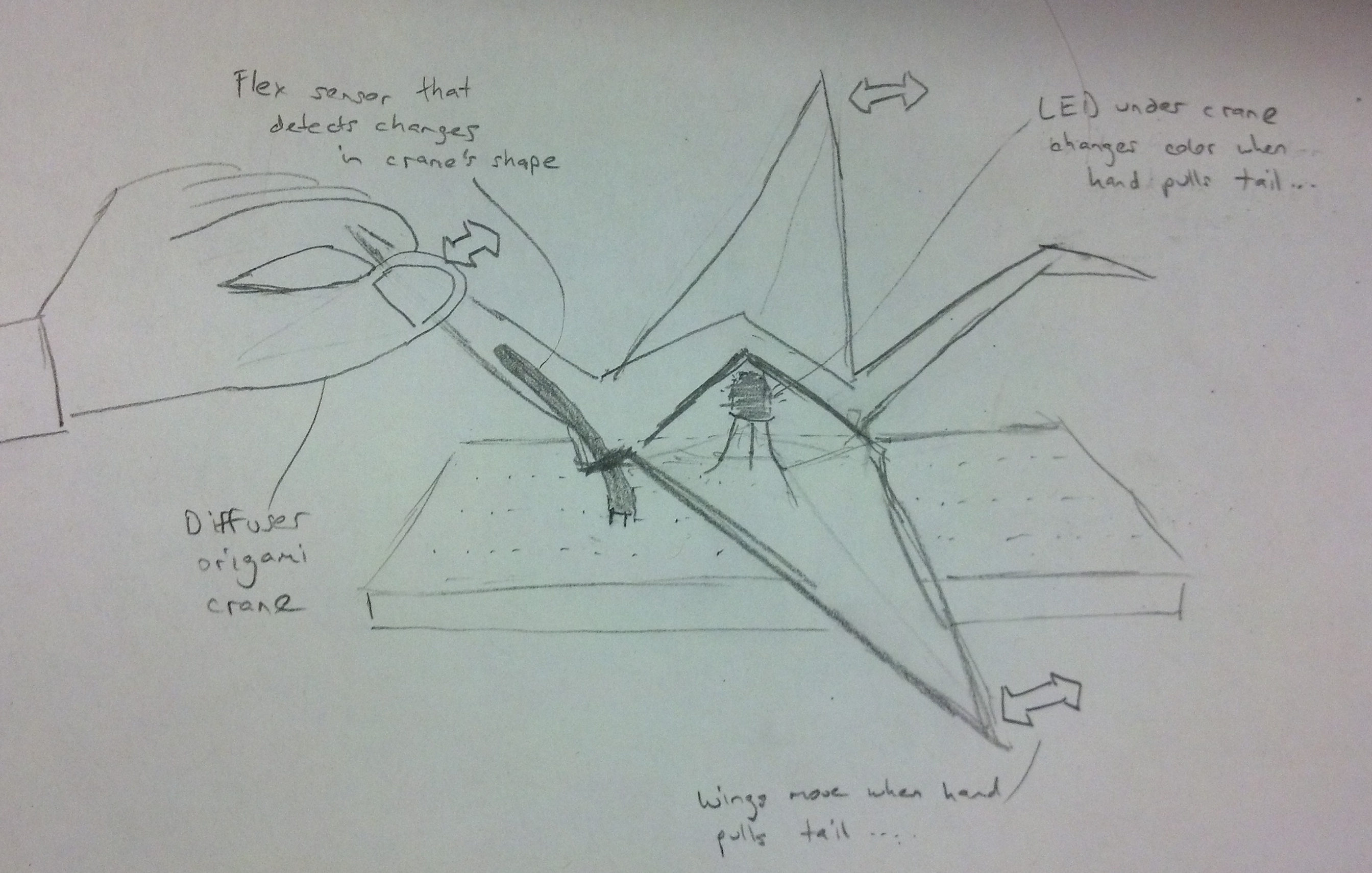
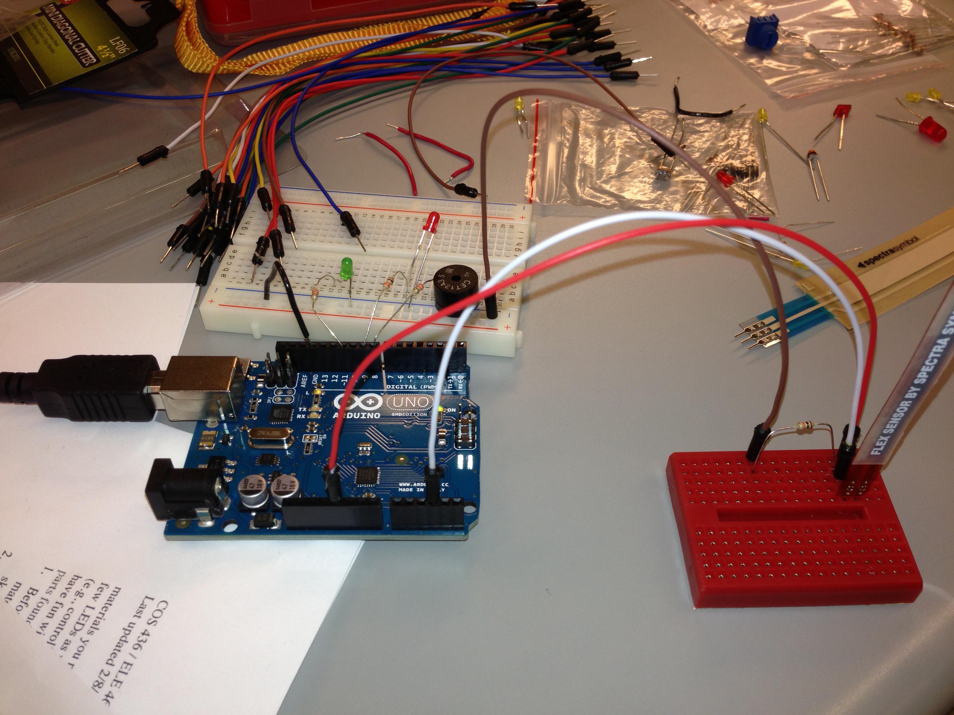
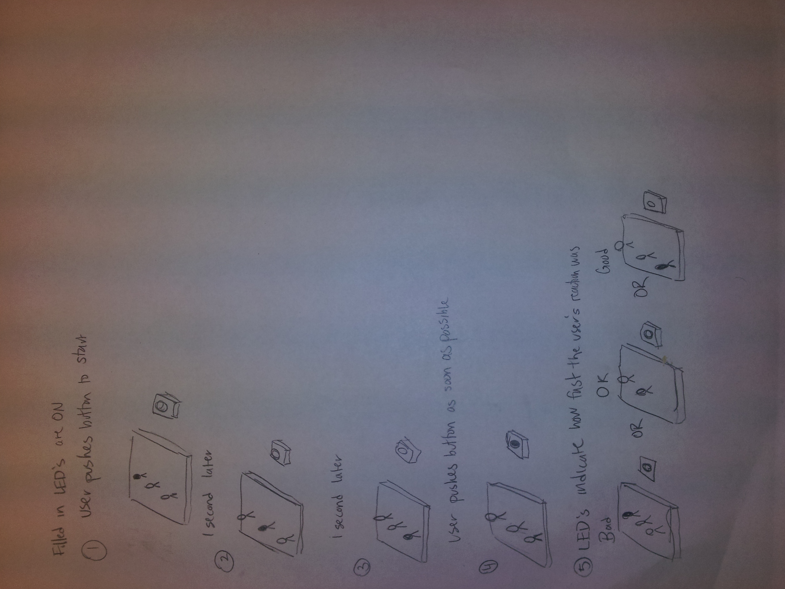
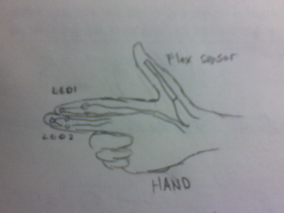
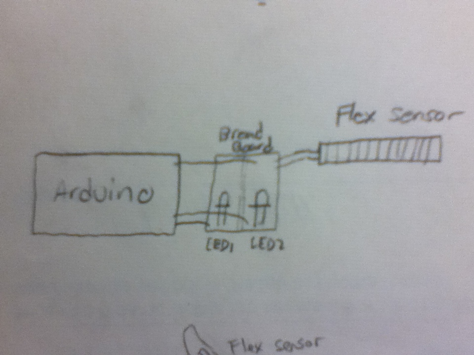
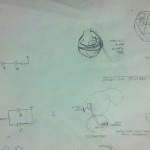
High-level sketch of our diffuser’s functionality.  When someone pulls on the Origami crane’s tail, the Arduino detects the change through the Flex sensor.

2013-02-16 16.52.29

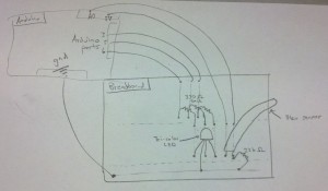
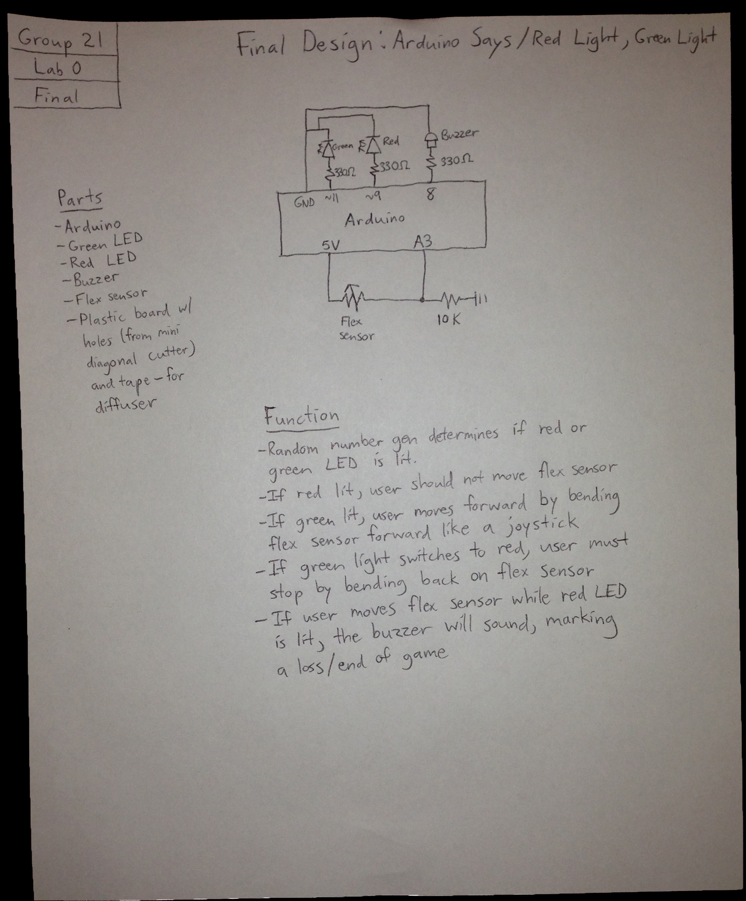
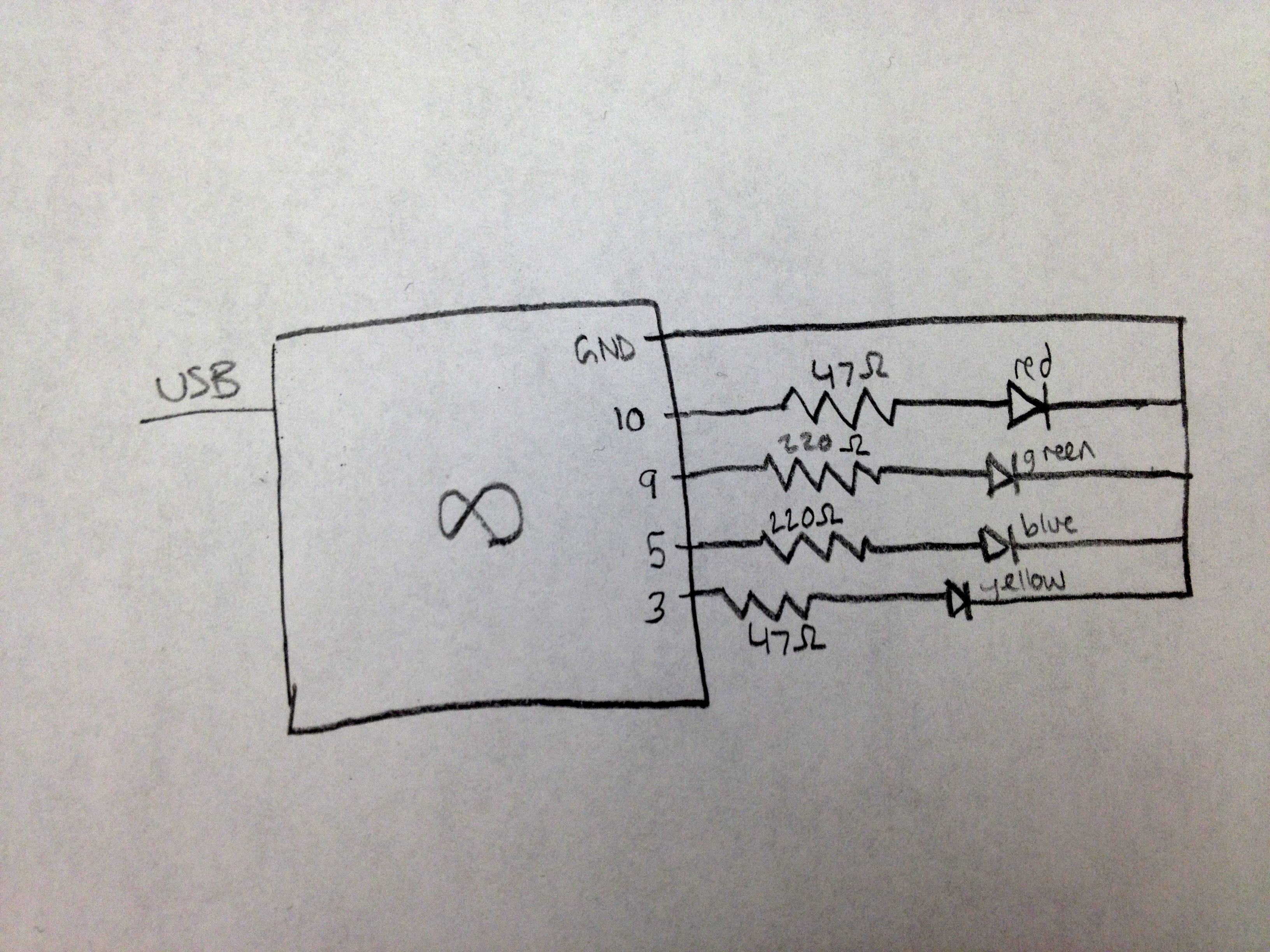
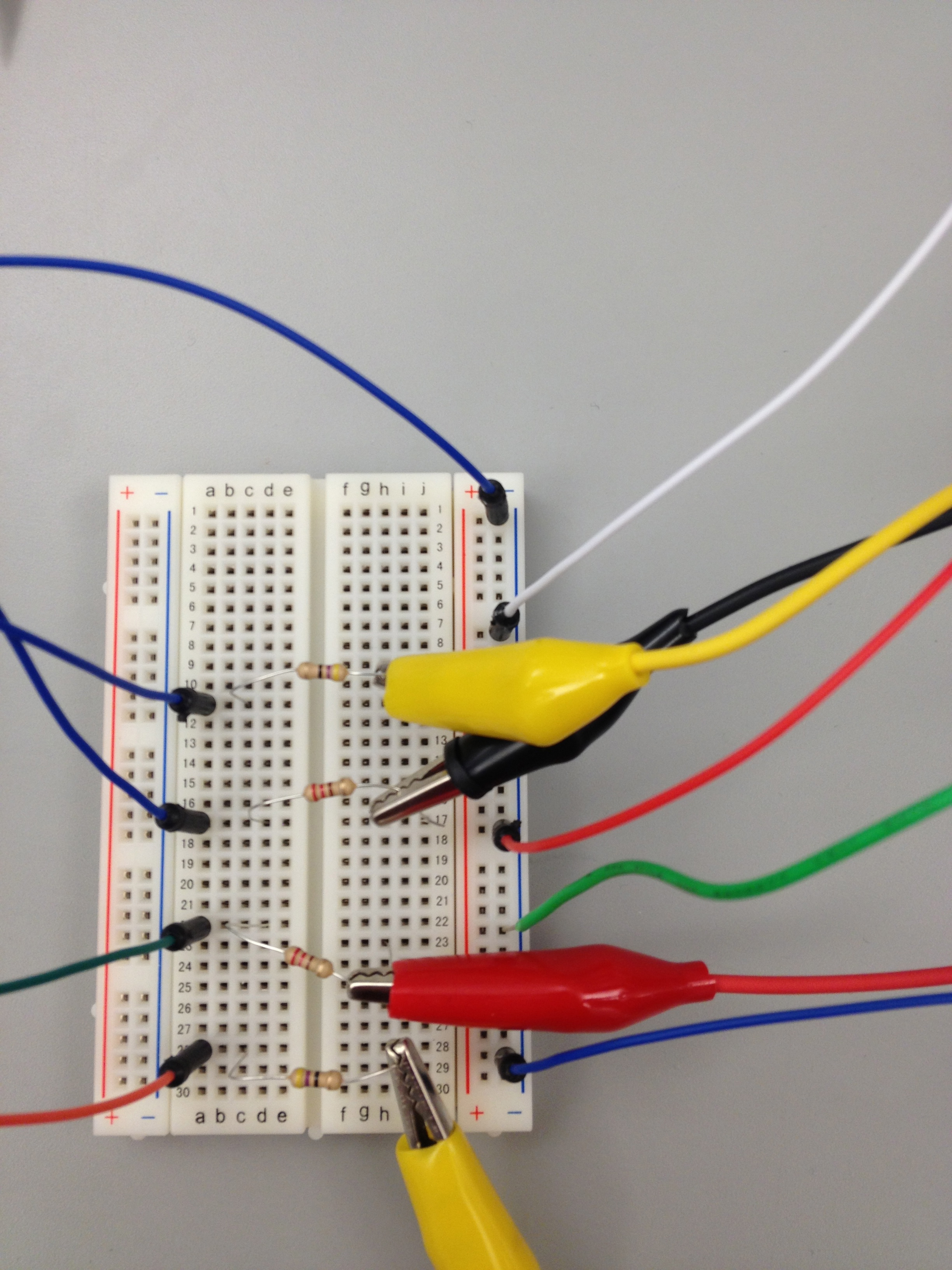
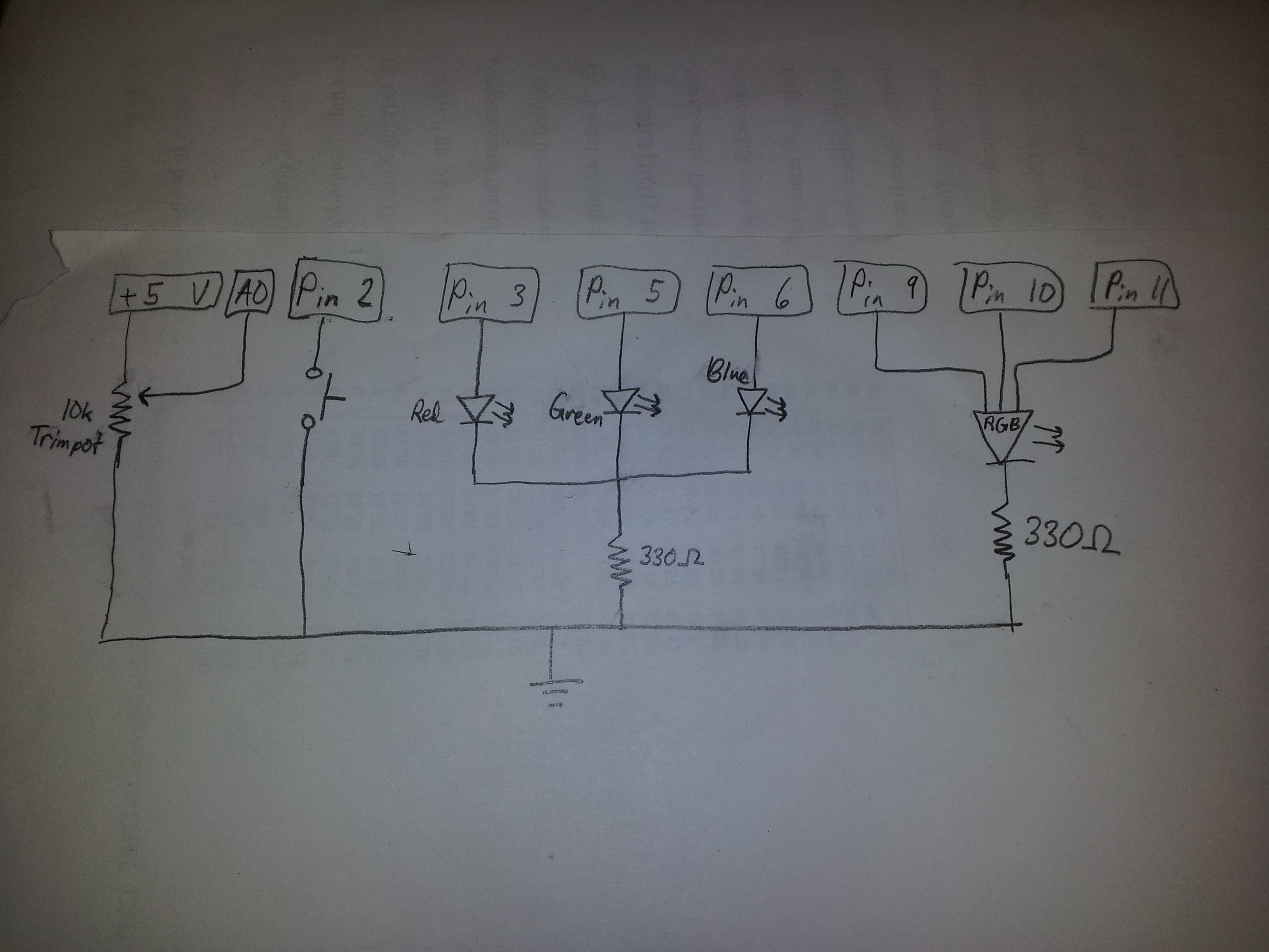
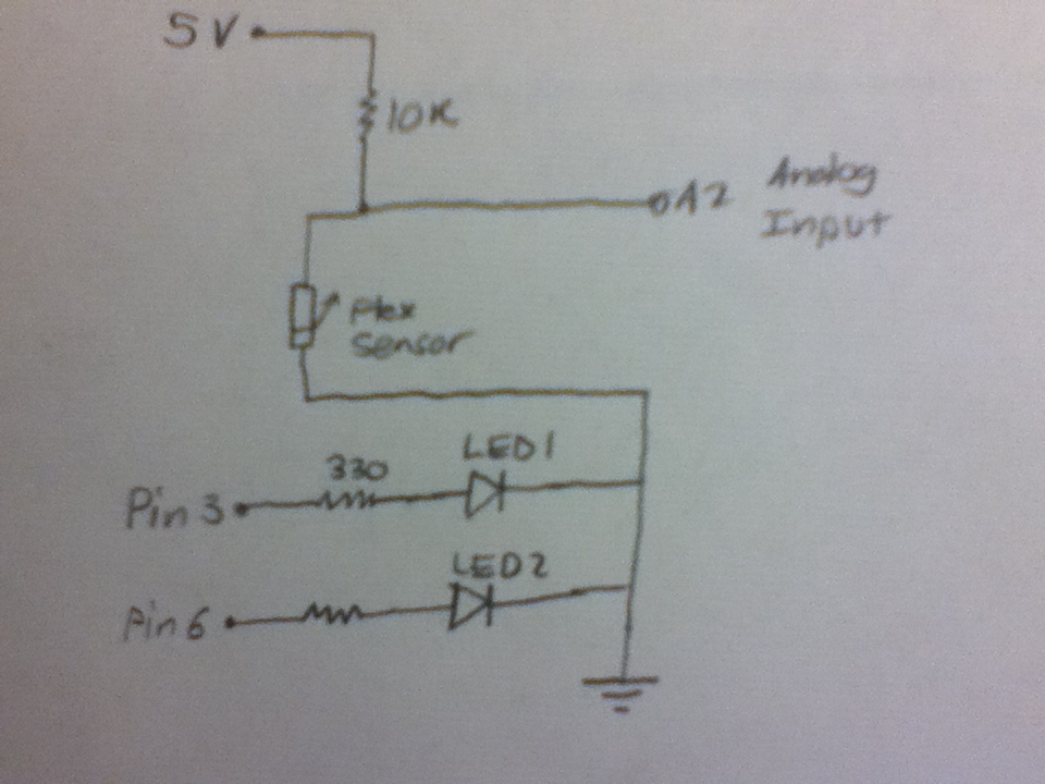
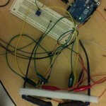
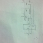
Low-level sketch of how our diffuser is built.  Our diffuser is built using a tri-color LED and a Flex sensor, with the LED three prongs each wired to the Arduino’s digital output pins and the Flex sensor wired to one of Arduino’s analog ports.

2013-02-16 16.46.00

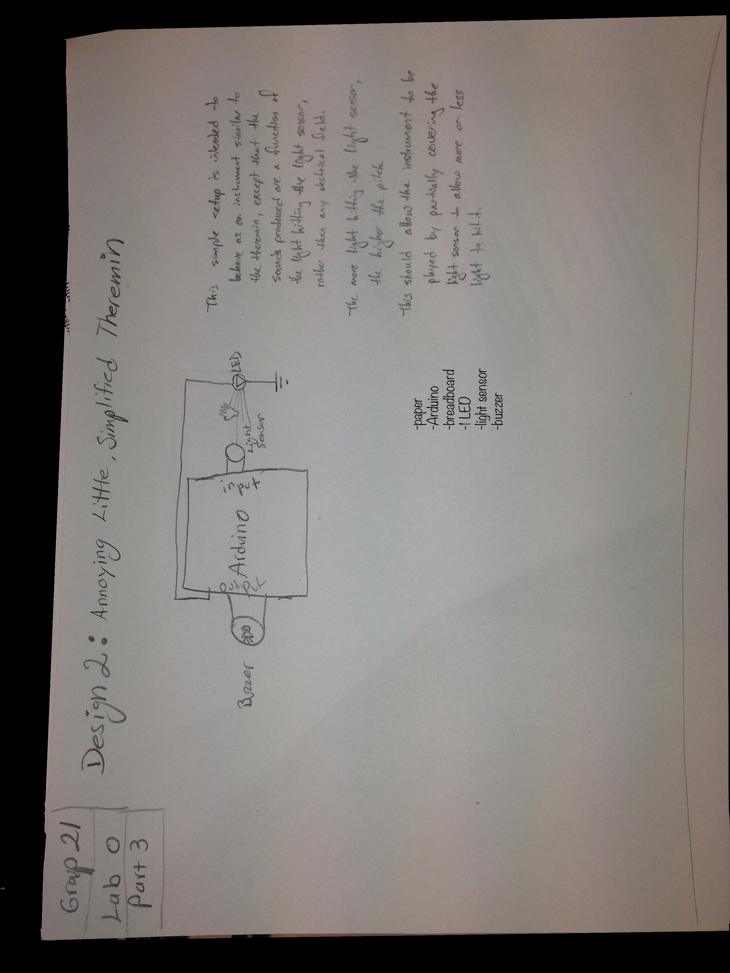
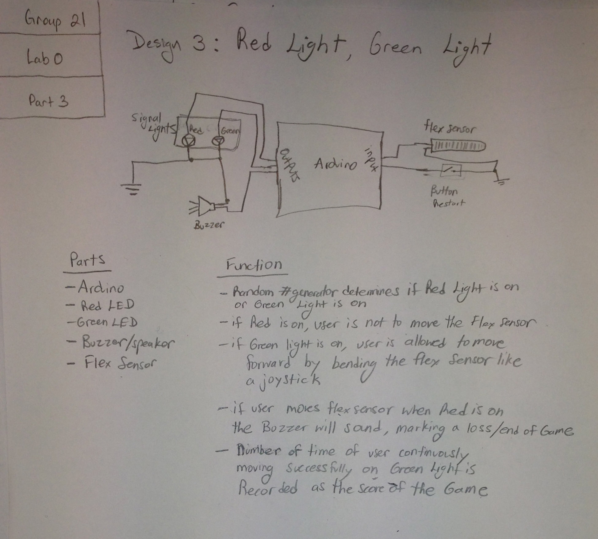
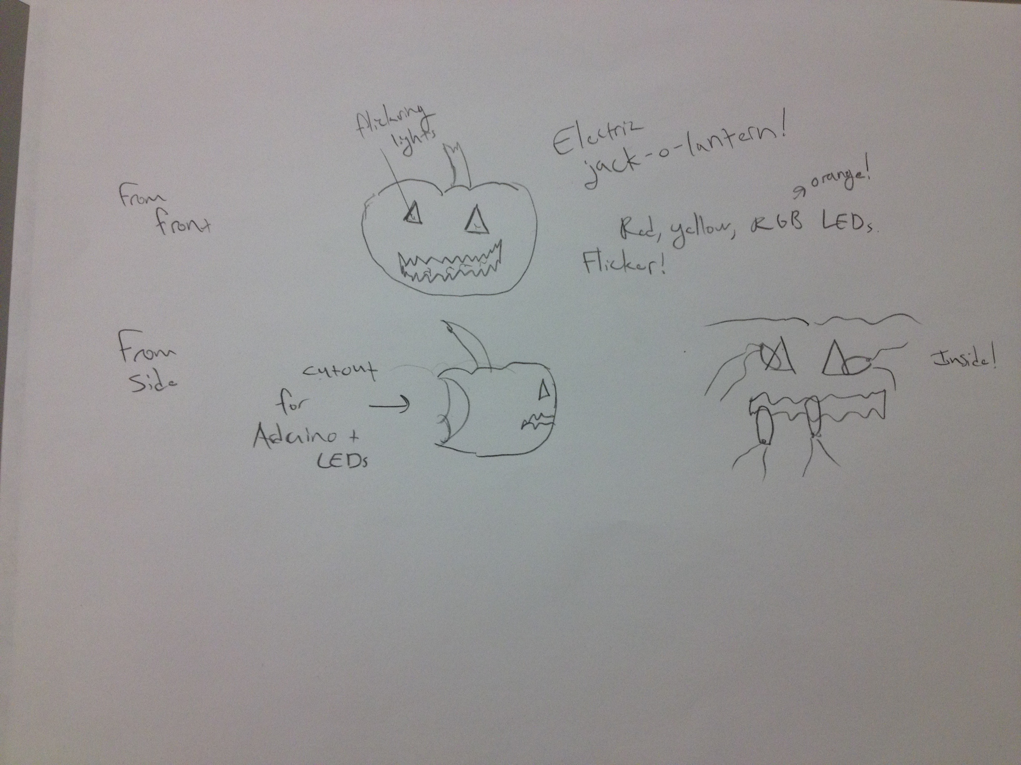
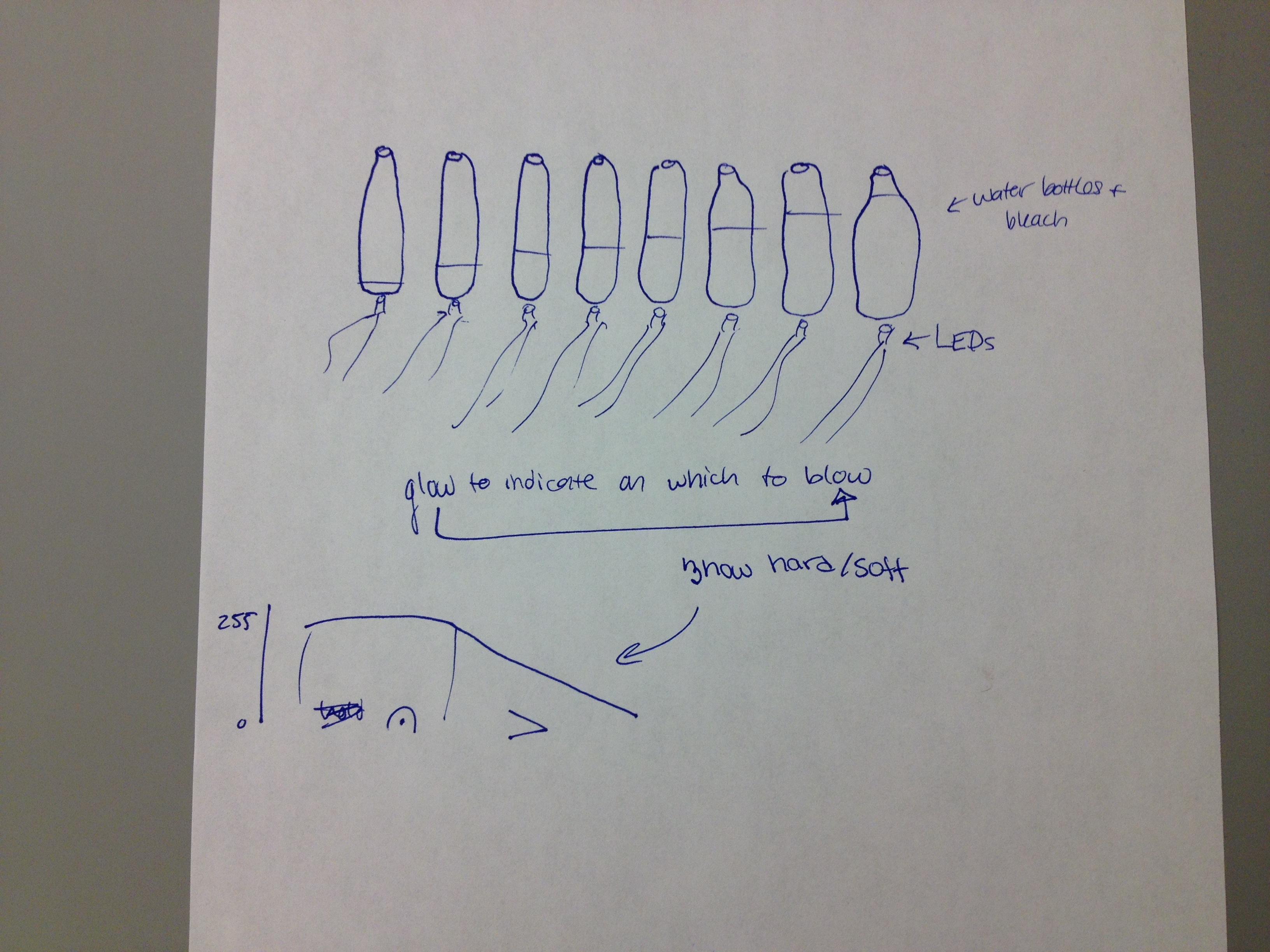
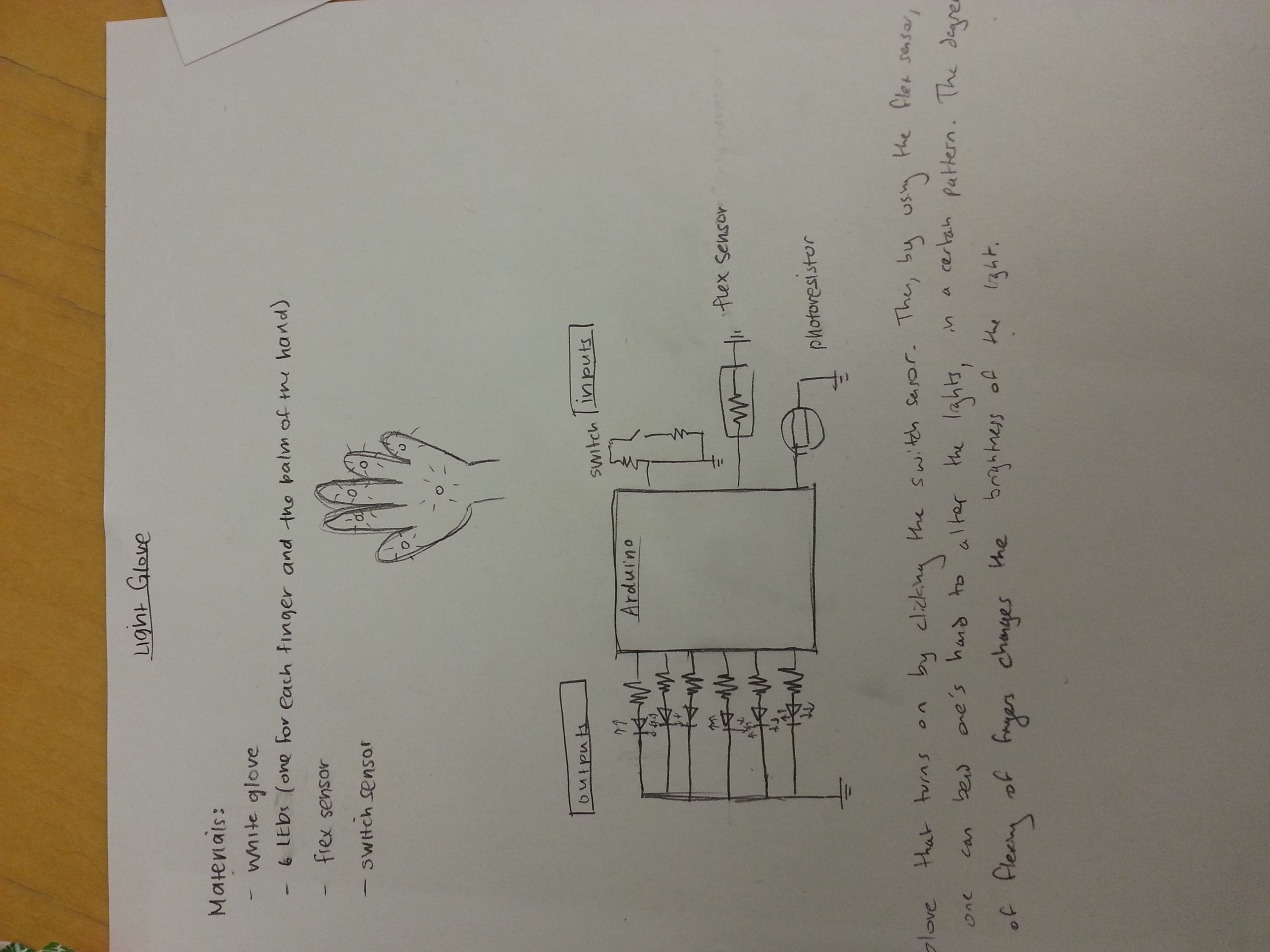
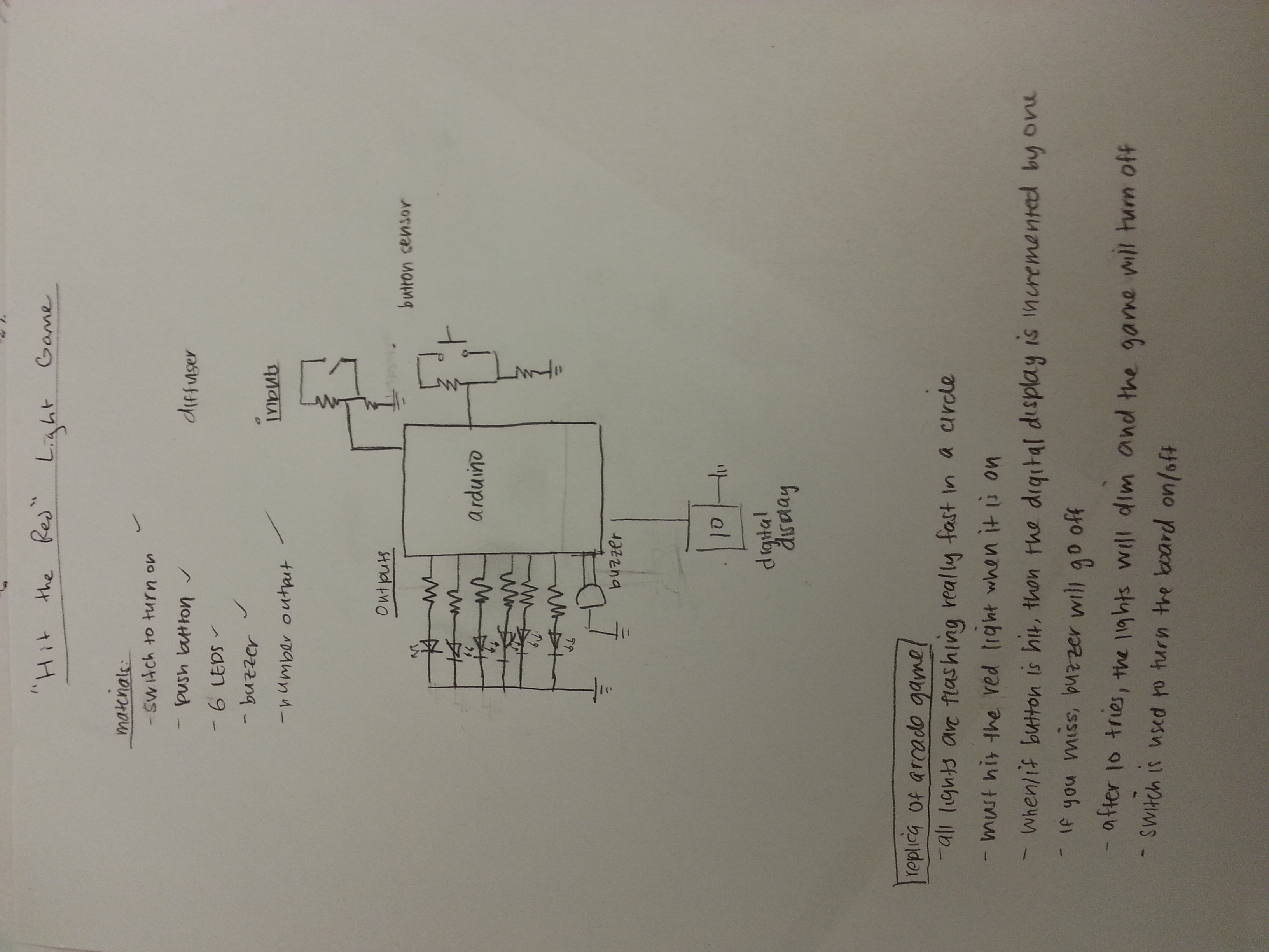
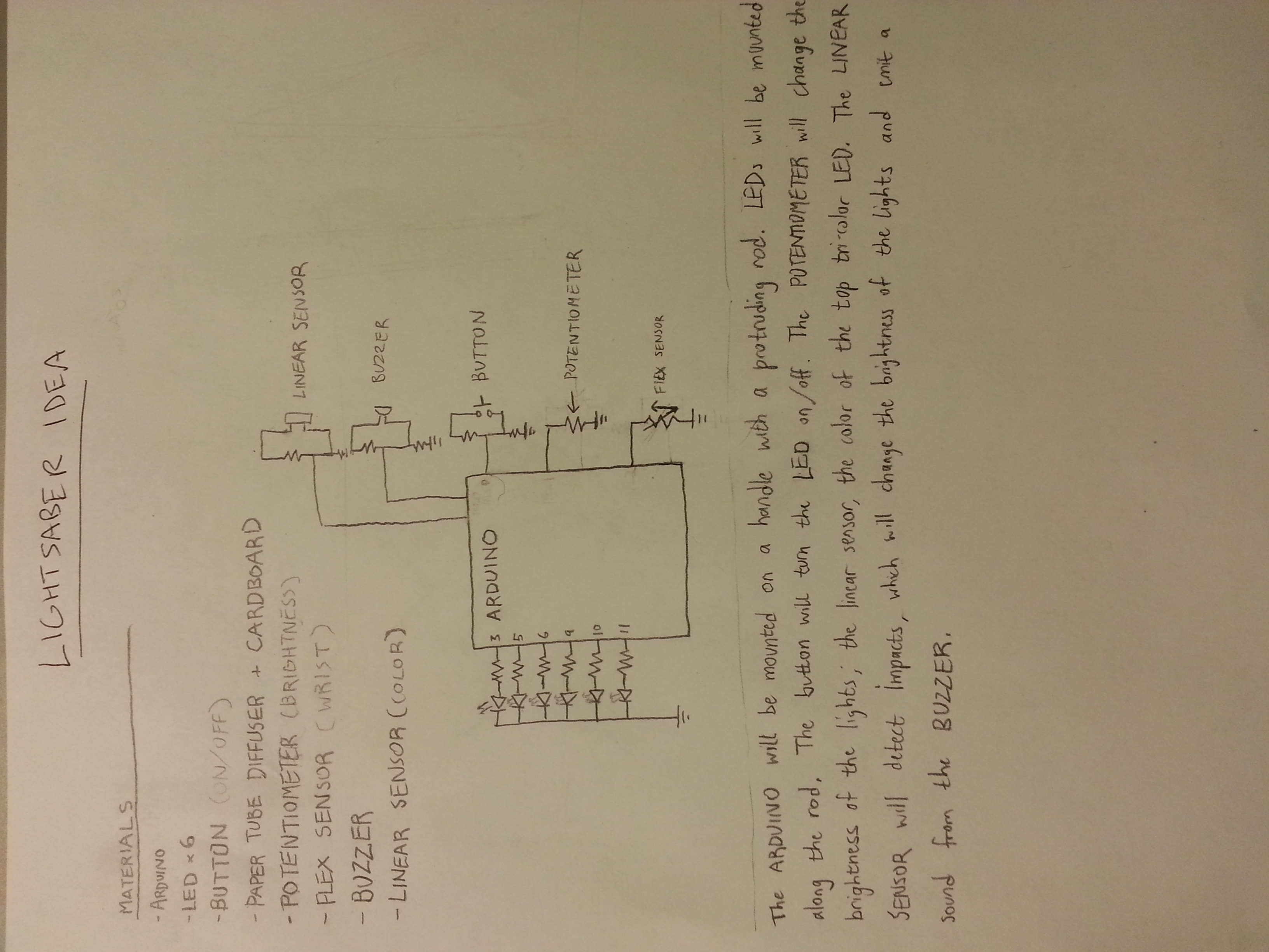
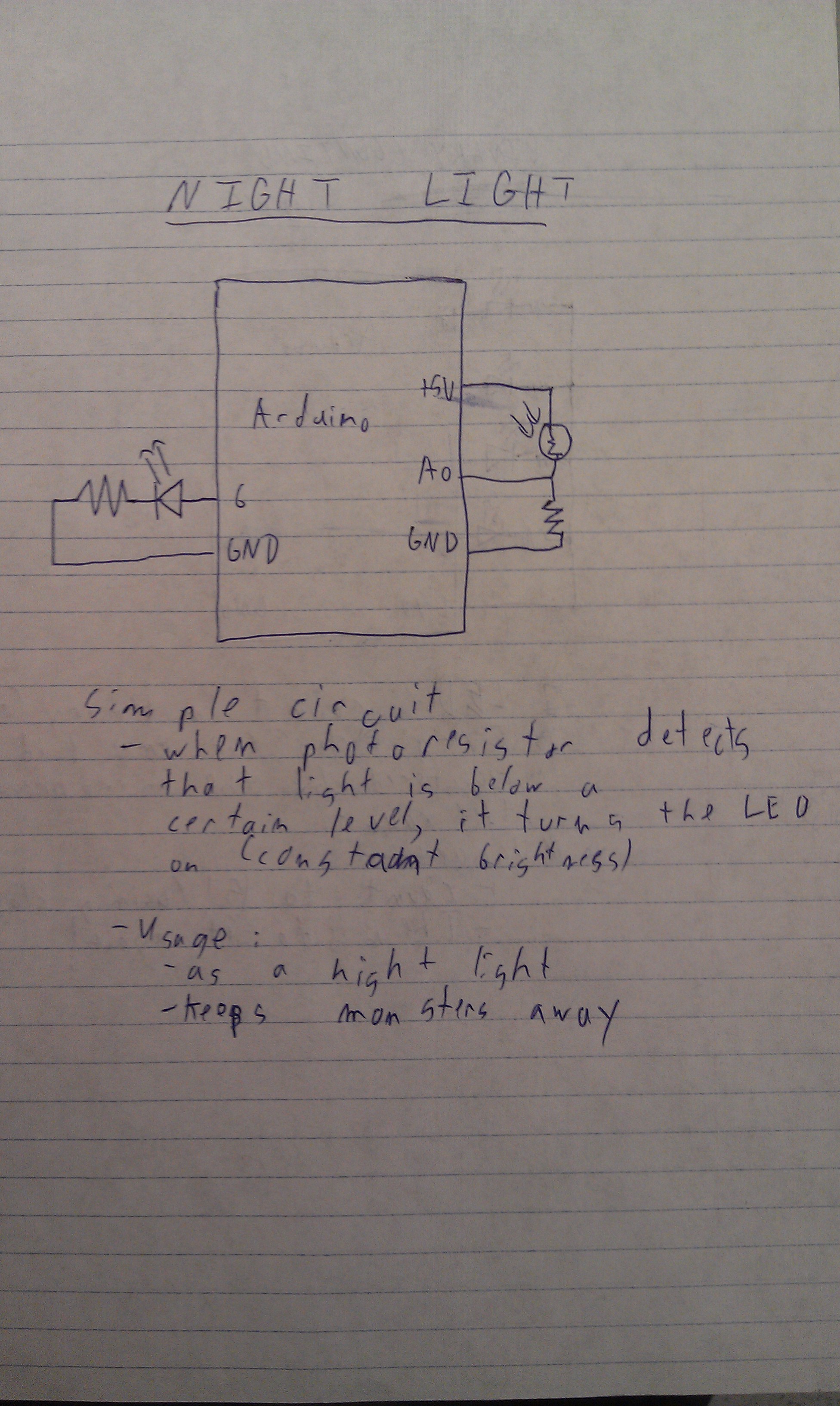
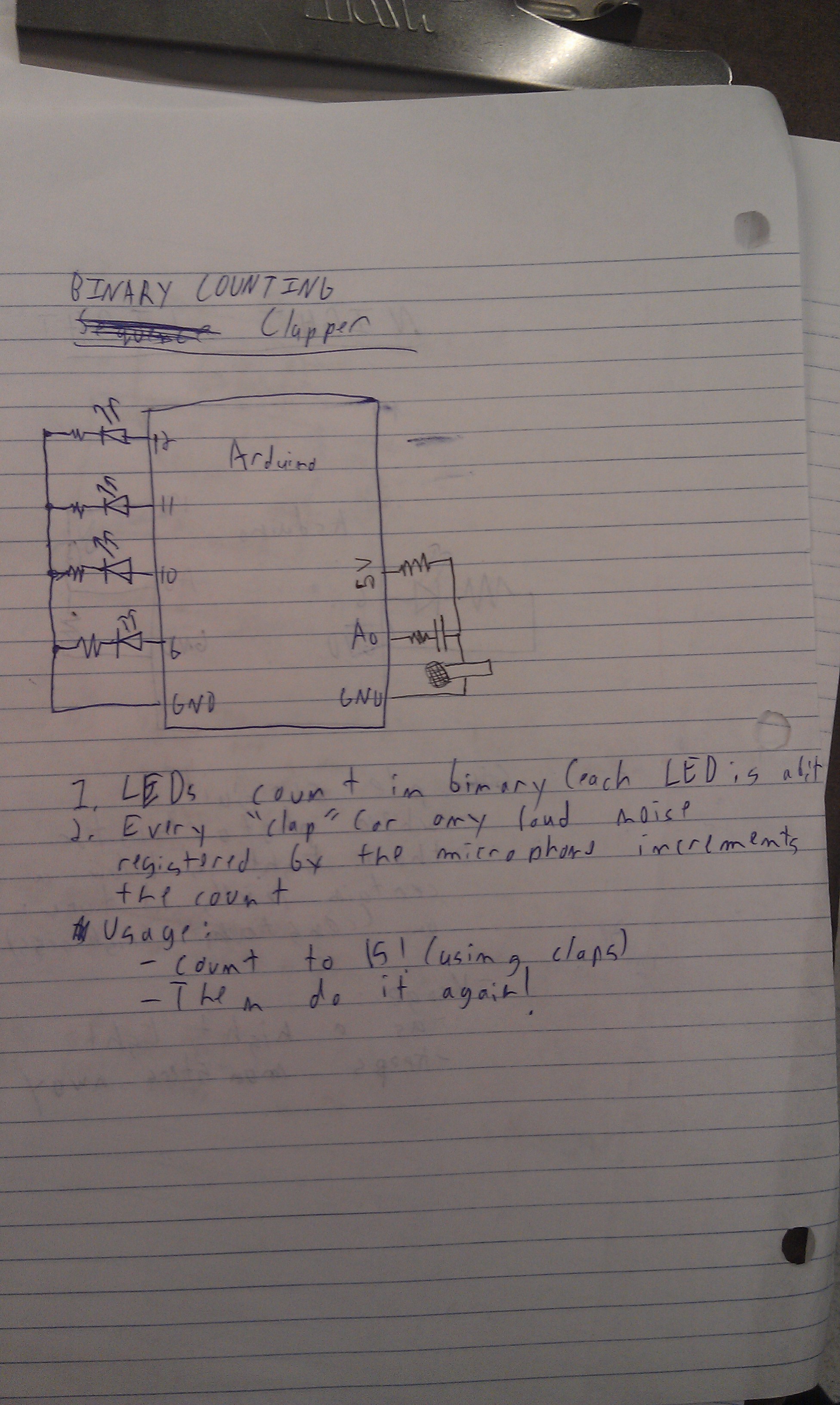
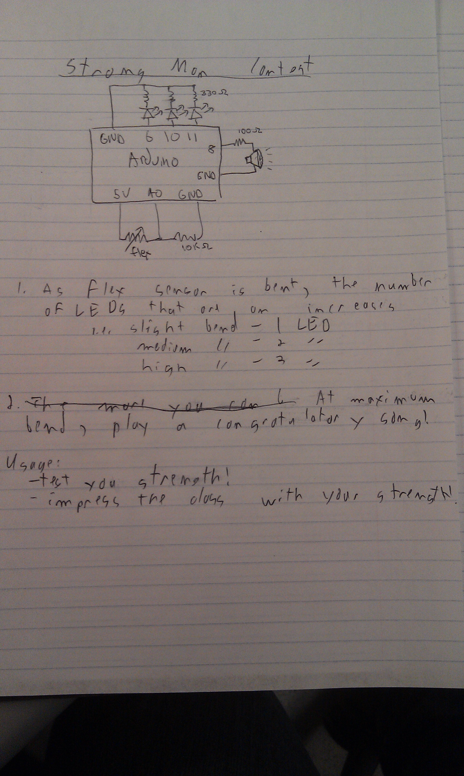
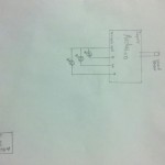
An earlier design we were considering for this project.  We gave up on the alarm clock because we thought having a diffusing crane was cooler 🙂

2013-02-16 16.45.46

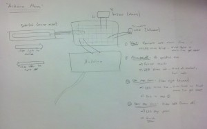
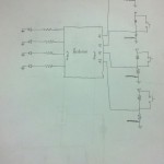
The low level sketch of the earlier design.

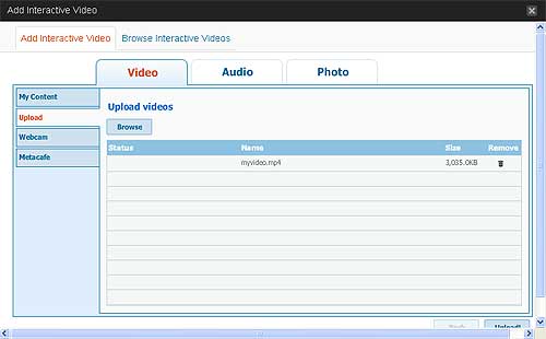
IV. Video of final system:

V. Parts used:

  • Arduino Uno
  • wires
  • 22 k ohm resistor
  • 3 330 ohm resistors
  • flex sensor
  • tricolor LED
  • wax paper crane

 VI. Instructions (see second diagram for more, as well)

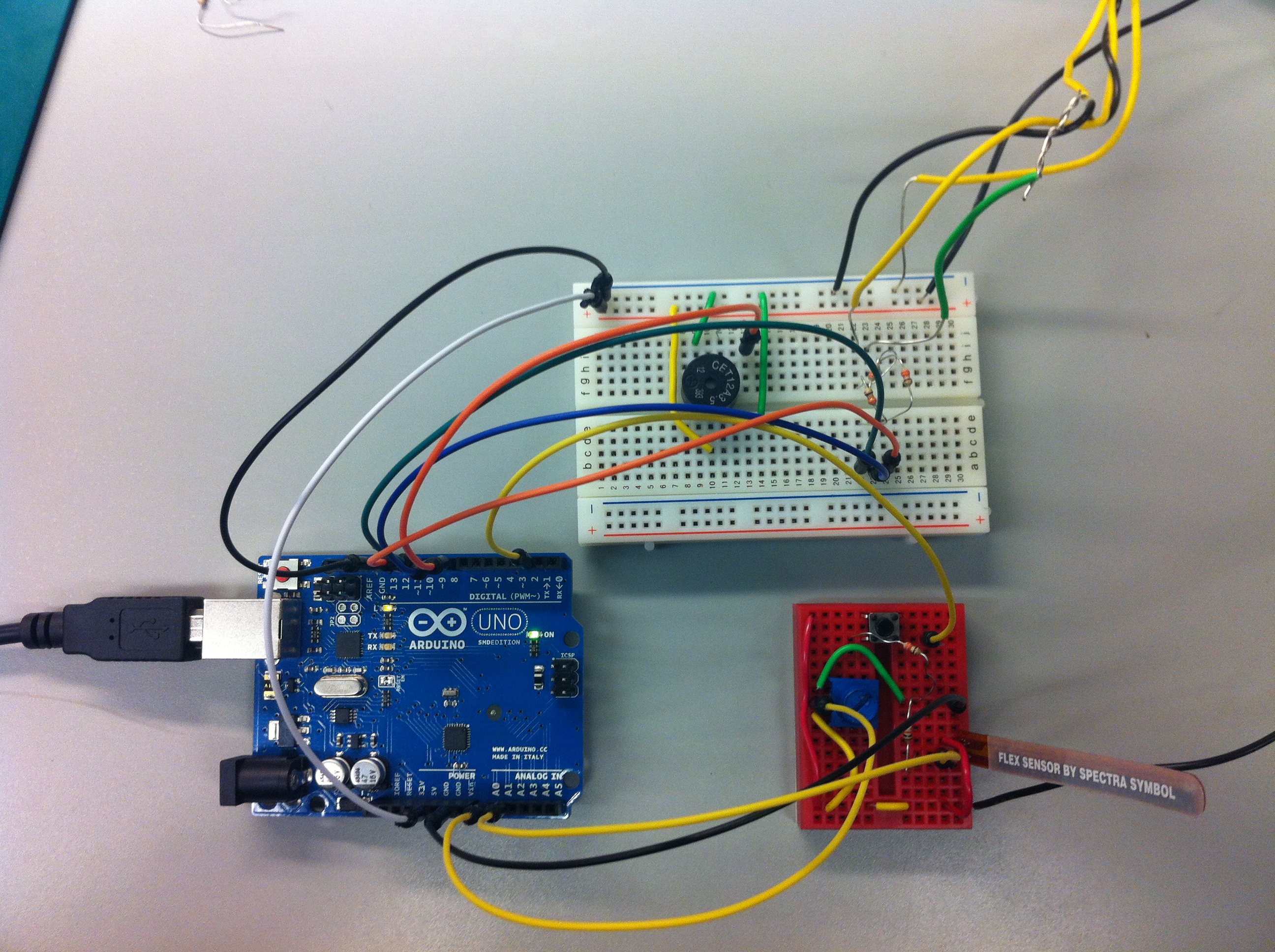
  1. Connect the parts to the Arduino board as shown in the diagram mentioned.
  2. Connect the ground leg of the tricolor led to ground. Connect each of the other legs to a digital output pin (3, 5, 6) on the Arduino, which one 330 ohm resistor for each leg.
  3. Connect the positive leg of the flex sensor to 5V, and the other leg to analog in pin A0. Also connect this to a 22 k ohm resistor going to ground.
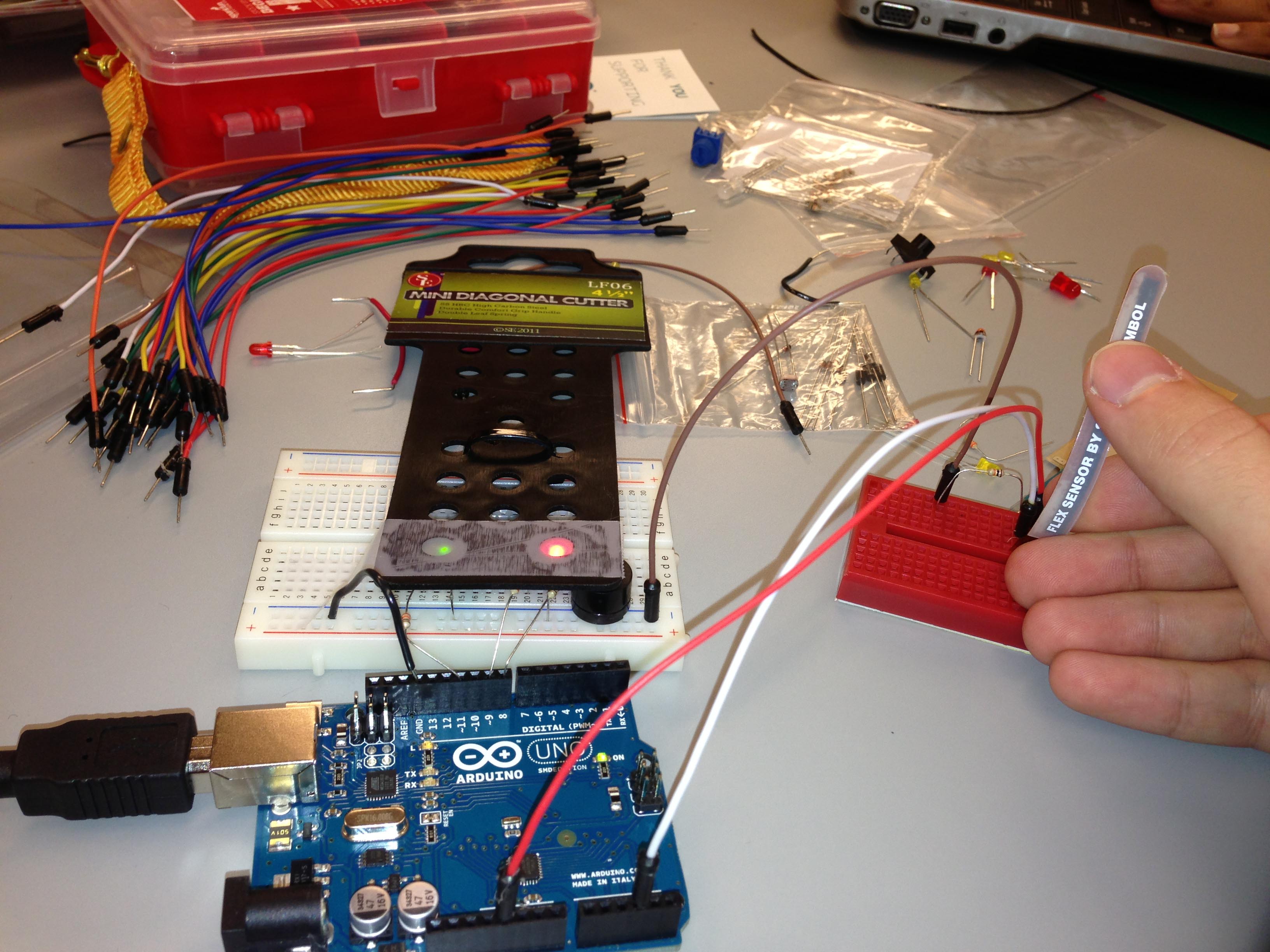
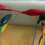
  4. Build a paper crane.  Stick the LED through the underside of the crane, and tape the flex sensor to the crane’s tail, so that pulling the tail causes both the crane’s wings to move and the flex sensor to register the change in resistance.

VII. Source code

const int ledPinRed = 6;
const int ledPinGreen = 3;
const int ledPinBlue = 5;
int flex = A0;

void setup()
{
  pinMode(ledPinGreen,   OUTPUT);
  pinMode(ledPinRed,   OUTPUT);
  pinMode(ledPinBlue,   OUTPUT);

  digitalWrite(flex, HIGH);
  analogWrite(ledPinRed, 255);
  Serial.begin(9600);
}

void loop() {
  byte brightness = analogRead(flex);
  if (brightness <   50) {
    analogWrite(ledPinRed, 0);
    analogWrite(ledPinBlue, 0);
    analogWrite(ledPinGreen, 255);
    delay(200);
    analogWrite(ledPinGreen, 0);
    analogWrite(ledPinBlue, 255);
  }
  else {
    analogWrite(ledPinGreen, 0);
    analogWrite(ledPinBlue, 0);
    analogWrite(ledPinRed, 255);
  }
  delay(200);
}

Arduino Says – Red Light Green Light

Group

Andrew Boik (aboik@)
Brian Huang (bwhuang@)
Kevin Lee (kevinlee@)
Saswathi Natta (snatta@)

Description

For our Part 3 we chose to implement a simple Red Light, Green Light game. We are using one red and one green LED to indicate when the user is supposed to stop or allowed to go. We are using the Flex sensor as a joystick where bending it in one direction signifies accelerating and not bending or bending in the other direction signifies stopping. If the green light is on, the user is allowed to “go” by bending the flex sensor forward to accumulate points in the game. If the red light is on, the user is supposed to “stop” by bending the flex sensor backwards. If the user by mistake “goes” while the red light is on, the buzzer will play a sad song signifying the end of the game. To play again, however, one need only reset the Arduino. We are using a random number generator to determine when the red light or the green light will be on. The diffuser is basically our traffic light contraption made of tape and plastic. Our project was primarily motivated by the desire to implement an interactive, joystick-controlled system. Ultimately, we think this project was a great success. We particularly like how we were able to make a responsive joystick with just a flex sensor. If we could change something, we would somehow add components to convey the gamer’s score. Unfortunately, in the current implementation, the gamer is completely oblivious to the number of points he has accumulated. Note: We could have used a button as the user control for go and stop, but we chose to use a flex sensor to give the user a feeling of a joystick. With a flex sensor, if we choose, we can also allow the user to go faster or slower and accumulate more points faster or slower instead of a simple stop and go. If you fail too many times, the police will (not) come after you with the siren from Lab group 25.

Sketches of Early Ideas

Bicycle Lights

Bicycle Lights

sketch2-group21

Simplified Theremin

sketch3-group21

Red Light Green Light 

Final Sketch

finalsketch

Demonstration Video

Parts used in design:

  • Arduino
  • Red LED
  • Green LED
  • Buzzer/speaker
  • Flex sensor
  • Plastic and tape for diffuser

Instructions:

  1. Setup LEDs, buzzer, and flex sensor
    1. Place the long end of each LED to the chosen Arduino digital output pin and the shorter end to ground
    2. The buzzer is also wired between an Arduino digital output pin (that can generate a PWM) and ground
    3. the Flex sensor is wired with a voltage divider between one pin and power and the other pin connects to a Arduino analog input pin to detect the resistance
      1. Note: if the voltage divider is not in place, the Arduino only reads a full high power and does not read the varying resistance when the flex sensor is bent
  2. Setup diffuser
    1. Diffuser is made of tape placed over two circular holes in a plastic packaging material. The red and green LED are placed under the two holes and are visible through the tape. the buzzer is covered by the plastic.
  3. Test baseline for flex sensor and change ‘go’ threshold as necessary
    1. Once the Flex sensor is connected, with the proper (~10K) voltage divider connected to power on one pin and the other pin connected to the Arduino, the Arduino software will display it’s reading of the input. You can bend it forward and backward to see how the values change. We chose a threshold value of 360, where values above the threshold are the “go” state and values below are the “stop” state
    2. The buzzer will sound if the red LED is on and the flex sensor is in the go state, signifying that the game is over.
Setup with Diffuser

Setup with Diffuser

Setup without Diffuser

Setup without Diffuser

 Code:

/*
Red Light/Green Light Game!
*/

#include "pitches.h"

int flexSensorPin = A3;
int redLED = 9;
int greenLED = 11;
int state; // holder for red/green light state
int pause = 250; // constant for use in error state
int leeway = 400; // time for player to switch
int interval = 5; // ticks before randomly generating a light
int counter = 0;
int goThreshold = 360; // threshold for stop/go.
                       // Values above are “go”
int score; // currently inconsequential,
           // but could be used to create top scorers

// notes in the melody:
int melody[] = {NOTE_C5, NOTE_B4, NOTE_AS4, NOTE_A4};

// note durations: 4 = quarter note, 8 = eighth note, etc.:
int noteDurations[] = {4, 4, 4, 1};

void setup(){
  Serial.begin(9600);
  pinMode(redLED, OUTPUT);
  pinMode(greenLED, OUTPUT);

  digitalWrite(redLED, HIGH); // initialize to red light
  digitalWrite(greenLED, LOW);
  state = 0;
  score = 0; // set score to zero
}

void loop(){
  if (counter >= interval) {
    state = random(2);
    light(state);
    counter = 0;

    delay(leeway); // give the player time to react
    leeway = leeway - 1; // make the game iteratively harder
  }

  int flexSensorReading = analogRead(flexSensorPin);
  switch (state) {
    case 0: // red light is on
      if (flexSensorReading <= goThreshold) { 
        // success! 
        score++;
      } 
      else { 
        failure();
      } 
      break;
    case 1:
      // green light is on 
      if (flexSensorReading > goThreshold) {
        // Good! Get points!
        score++;
      }
      else {
        // we don’t punish for not going, you just get no points
      }
      break;
    default:
       // we should never get here
       error();
  }

  Serial.print("state: ");
  Serial.println(state);
  Serial.println(flexSensorReading); // debugging?

  counter++;
  delay(pause);
}

void light(int status){
  switch (status) {
    case 0: // red light!
      digitalWrite(redLED, HIGH);
      digitalWrite(greenLED, LOW);
      break;
    case 1: // green light!
      digitalWrite(redLED, LOW);
      digitalWrite(greenLED, HIGH);
      break;
    default:
      //this should never happen
      error();
  }
}

void error() {
  while (true) {
    digitalWrite(redLED, LOW);
    digitalWrite(greenLED, LOW);
    delay(pause);
    digitalWrite(redLED, HIGH);
    digitalWrite(greenLED, HIGH);
    delay(pause);
  }
}

void failure() {
  // iterate over the notes of the "fail" melody:
  for (int thisNote = 0; thisNote < 4; thisNote++) {
    // to calculate the note duration, take one second
    // divided by the note type.
    // e.g. quarter note = 1000 / 4, eighth note = 1000/8, etc.
    int noteDuration = 1000/noteDurations[thisNote];
    tone(8, melody[thisNote],noteDuration);

    // to distinguish the notes, set a minimum time between them.
    // the note's duration + 30% seems to work well:
    int pauseBetweenNotes = noteDuration * 1.30;
    delay(pauseBetweenNotes);
    // stop the tone playing:
    noTone(8);
  }
error();
}


Bottle Organ RockBand

Erica Portnoy (eportnoy@)
Bonnie Eisenman (bmeisenm@)
Mario Alvarez  (mmcgil@)
Valya Barboy (vbarboy@)

Bottle Organ RockBand:

The Bottle Organ RockBand is a musical tutorial: it lights up the bottle that you should blow in next, teaching you to play a song (specifically, Mary Had a Little Lamb)! We were inspired to do this project by little kids’ instructional pianos, whose keys light up to teach people to play simple songs. Three of us play the flute, so the bottle organ was a natural and cheap choice of instrument. Also, we thought that light would diffuse really well through a water-milk mixture, making the instructions easy to follow (and it would look cool!). We thought the diffusion of our LEDs through the fluids worked really well. We also liked the fact that the different notes were different colors, because it makes the tutorial easier to follow. Finally, we’re proud of the tuning of the bottles. Originally we had hoped to build a larger-scale organ to span an entire octave, but because of the limited number of LEDs we could not do that. We also thought about making it more interactive (using the SoftPot to adjust tutorial speed, having a user compose a song and the tutorial play it back, etc.) We ultimately decided, however, that it would be more beneficial to focus our efforts on making the output device, because adding sensors would yield only minimal gain. Another limitation is that currently our song is hardcoded, so it can only play one song at a time. That being said, the notes themselves are in a separate array that our code reads in and parses, so giving it any other song would be easy. Finally, one major design flaw we had was that the bottles were standing very close to our electronics. If we were going to do this again, we would keep our bottles in some container, safely away from our Arduino. Overall, we are pleased with the result. We even did a user test!

Sketches:

Binary Balloon Stopwatch - counts seconds by giving the binary number via lit-up LEDs. Didn't work because we don't have helium, and have too few LEDs.

Binary Balloon Stopwatch – counts seconds by giving the binary number via lit-up LEDs. Didn’t work because we don’t have helium, and have too few LEDs.

Diffusing light through a pumpkin so that it looks like a flame - ultimately cool but kind of worthless...

Diffusing light through a pumpkin so that it looks like a flame – ultimately cool but kind of worthless…

Bottle Organ RockBand - our final design!

Bottle Organ RockBand – early sketches of our final product!

A video of our final result:

Showing various people playing our final product, and the making of our Bottle Organ!

List of materials:

  • 1 Arduino
  • 2 220 Ohm resistors
  • 2 47 Ohm resistors
  • 1 USB cable
  • 8 alligator clips
  • 9 wires
  • 1 breadboard
  • 4 LEDs
  • 4 plastic bottles, filled with a water and a few drops of milk
  • Online tuner

Instructions!

IMG_1991IMG_1990

Once you have the necessary materials, start by building the circuit, following the diagram included. The circuit should be 4 LEDs and resistors in parallel, with all connecting to the ground on the Arduino. We used weaker resistors for the weaker LEDs, to make them all closer in brightness. Using alligator clips to connect to the LEDs is useful for positioning them beyond the breadboard. Each LED is then placed under a corresponding plastic bottle so that the light diffuses upwards. To set up the bottles: acquire four plastic bottles. If necessary, remove their labels. Then, use an online tuner such as this one to determine the volume of liquid necessary to produce the desired note for each bottle. We recommend simple trial and error using water. Mark the level and note on the bottle with a marker if desired. Water doesn’t diffuse light very well. In order to improve diffusion, add a small quantity of milk to each bottle. We used a standard soda bottle cap to measure out the milk, and used between half of a capful and a whole capful for each bottle; add milk until it looks cool to you, testing diffusion using an LED. We also experimented with some other liquids, such as tea; we encourage you to experiment with liquids as well. Volume, not density, determines pitch, so the type of liquid shouldn’t matter. Finally, place the bottles above the LEDs, plug the USB cable into the Arduino and the computer, and start making music!

The final set-up should look something like this:Photo Feb 13, 9 07 54 PM

Code:

/*****
 * File: mary_lamb
 * Description: blinks LEDs to play
   Mary Had a Little Lamb.
 * HCI L0
 * netids: bmeisenm, mmcgil, vbarboy, eportnoy
 *******/

// Define which pins represent each note.
const int cpin = 3;
const int dpin = 5; 
const int epin = 9; 
const int gpin = 10;

void setup()
{
  // initialize the serial communication:
  Serial.begin(9600);
  // initialize pins output:
  pinMode(cpin, OUTPUT);
  pinMode(dpin, OUTPUT);
  pinMode(epin, OUTPUT);
  pinMode(gpin, OUTPUT);
}

// Make a pulse at pin for a length of time
void pulse(int pin, double time)
{
  int maxbright = 255;
  for (int i=0; i <= maxbright; i++) {
    analogWrite(pin, 255 - i);
    delay(time/255.0);
  }
}

// "Plays" a song
void playsong(int notes[], int lengths[], int numnotes) {
  for (int i = 0; i < numnotes; i++) {
    pulse(notes[i], lengths[i]);
  }
}

// Main run loop.
void loop() {
  // Defines pulse lengths.
  double shortpulse= 1500;
  double shorterpulse = shortpulse * 0.8;
  double longpulse = shortpulse * 1.5;
  // Defines the song! (in terms of pins & lengths)
  int notes[26] = {epin, dpin, cpin, dpin,
                 epin, epin, epin, dpin,
                 dpin, dpin, epin, gpin,
                 gpin, epin, dpin, cpin,
                 dpin, epin, epin, epin,
                 epin, dpin, dpin, epin,
                 dpin, cpin};
  int lengths[sizeof(notes)];
  for (int i=0; i < sizeof(notes); i++)
    lengths[i] = shortpulse;
  lengths[6] = longpulse;
  lengths[9] = longpulse;
  lengths[12] = longpulse;
  lengths[17] = shorterpulse;
  lengths[18] = shorterpulse;
  lengths[19] = shorterpulse;
  lengths[20] = shorterpulse;
  lengths[sizeof(notes) - 1] = longpulse;
  // Play song.
  playsong(notes, lengths, sizeof(notes));
  // Delay at end just for fun.
  delay(4000);                 
}

Color Mixer

i. Group: Philip Oasis, Gene Merewether, Alice Fuller, Rodrigo Menezes

ii. We built a color mixer, in which the user turns a potentiometer to adjust the brightness of red, green, and blue LEDs, and then observes the mixed output of the three hues on a single RGB LED.  The purpose for the user is to observe how RGB colors are mixed, as well as a fun way to try making new colors.  The tissue paper diffuser is meant to spread out the light and make it easier to view.  We feel that it is successful in achieving these goals, and that the interface is relatively easy to understand and operate.  We enjoyed using the final product and trying to make interesting colors.  We might have liked to use more LED’s to make the panel brighter and easier to see.

iii. Sketches of possible designs

20130213_201102

A reaction game where the user tries to hit the push button after the final LED is lit.

rgb-two-step-memory-game


A memory game in which the user uses a button to select the LED which was lit a certain number of lights ago.

20130206_210759 20130206_220008


A color mixer in which the user selects brightness of red, green, and blue LED’s and then observes the combination of those hues.

iv. Video of the system in action

http://www.youtube.com/watch?v=RQmMFz5ngmM

v. Parts list

  • (1) Red LED
  • (1) Green LED
  • (1) Blue LED
  • (1) Tricolor LED
  • (1) 10k trimpot
  • (4) 330 ohm resistor
  • (2) Breadboard

vi. Instructions to recreate design

  1. Connect potentiometer to analog pin A0, powered by 5v
  2. Connect push button to digital pin 2, powered by 5v, with a 330Ω resistor.
  3. Connect red, green, and blue LED’s to digital pins 3, 5, and 6 (respectively), all powered by 5v and each with a 330Ω resistor.
  4. Connect the rgb LED to digital pins 9, 10, and 11, again powered by 5v, and with 330Ω resistors.
  5. (optional) Cover the LED’s with a tissue paper diffuser

vii. Source code

const int sensorPin = 0;
const int buttonPin = 2;
const int redPin = 3;
const int greenPin = 5;
const int bluePin = 6;
const int ledRedPin = 9;
const int ledGreenPin = 10;
const int ledBluePin = 11;
 
const int RED_STATE = 0;
const int GREEN_STATE = 1;
onst int BLUE_STATE = 2;
 
int prevButtonState;
int systemState;
int redValue;
int greenValue;
int blueValue;
void setup() {
    Serial.begin(9600);
    pinMode(buttonPin, INPUT);
    pinMode(redPin, OUTPUT);
    pinMode(bluePin, OUTPUT);
    pinMode(greenPin, OUTPUT);
    pinMode(ledRedPin, OUTPUT);
    pinMode(ledGreenPin, OUTPUT);
    pinMode(ledBluePin, OUTPUT);
 
    prevButtonState = HIGH;
    systemState = RED_STATE;
    redValue = 0;
    greenValue = 0;
    blueValue = 0;
}
 
void loop() {
    int buttonState = digitalRead(buttonPin);
    int sensorValue = analogRead(sensorPin)/4;
    Serial.println(sensorValue);
 
    if (buttonState == HIGH && prevButtonState == LOW)
    {
        systemState = systemState + 1;
        if (systemState == 3)
        {
            systemState = 0;
        }

    }
    prevButtonState = buttonState;
    switch (systemState)
    {
         case RED_STATE:
             redValue = sensorValue;
             analogWrite(redPin, redValue);
             analogWrite(greenPin, 0);
             analogWrite(bluePin, 0);
             break;
         case GREEN_STATE:
             greenValue = sensorValue;
             analogWrite(redPin, 0);
             analogWrite(greenPin, greenValue);
             analogWrite(bluePin, 0);
             break;
         case BLUE_STATE:
             blueValue = sensorValue;
             analogWrite(redPin, 0);
             analogWrite(greenPin, 0);
             analogWrite(bluePin, blueValue);
             break;
         }

analogWrite(ledRedPin, redValue);
analogWrite(ledGreenPin, greenValue); 
analogWrite(ledBluePin, blueValue); 
} 

Mini Lightsaber

PART I Names

Karena Cai (kcai@)
Jean Choi (jeanchoi@)
Stephen Cognetta (cognetta@)
Eugene Lee (eugenel@)

PART II

We built a mini Lightsaber, which makes ‘authentic’ lightsaber noises when held , turns on and off with a button, changes brightness based on a knob, and also changes brightness and noise frequency when you flex your wrist. We built it because it is awesome. More seriously, we built this because the focus is on the light diffuser, as per the project description, but because it also allowed us to make a lot of interesting modifications to it. The project was an immense success. Although the lightsaber wasn’t as long or bright as we would have liked, that was a limitation of resources, not of effort. We liked that it changes brightness with both the potentiometer and flex sensor, and incorporated many types of sensors. It also interfaces with the body in an interesting way, as wrist motion affects the brightness of the LEDs. We found that the LEDs on pins 3 and 11 turn off when the buzzer (on pin 8) sounded. We were not entirely sure why. We also decided not to change the color of  the tri-color LED because it would take up 3 of the 6 analog output pins. For simplicity, we decided to connect LEDs in series, so we didn’t need to use these two analog output pins. If we were to do this again, we would begin by planning our circuit design better – we had to split components between two breadboards for greater ergo-dynamics  If we were to do this again, we would try to use more powerful LEDs of the same color to closer resemble a lightsaber. Most importantly, we would like to have some kind of impact sensor so the lightsaber can react when it is used to hit things.

PART III Sketches

20130208_152222

Light Glove

Glove turns on by clicking the switch, by using the flex sensor, one can bend ones hand to alter the light in a pattern determined by their hand motions. The flex sensor would change brightness of the LEDs.

20130208_151839

Hit the right light

Replica of an arcade game, where you must hit the proper LED when its on. The six LEDs are arranged in a circle and turn on in succession. When you hit the button when the LED is on, the digital display is incremented by one. If you miss, the buzzer will go off, but the game will continue. After 10 misses, the lights will dim and the game will end.

20130208_155053

Lightsaber

The arduino will be mounted on a handle (not included) with a protruding rod, along which the LEDS will be mounted. Button will turn the LEDs on/off, the potentiometer will change the brightness of the lights, the linear sensor (not included) will change the color of the top tri-color LED. The flex sensor will detect impacts which change the brightness of the lights and emit a sound from the buzzer.

Note: we did not include the linear sensor into our final product.

PART IV : Photo and video showing final system in action

photo

The circuit

photo (3)

In action

photo (2)

Palm of glove

photo (1)

Back of glove

PART V : List of parts used in final system: 

  • 4 LEDs
  • 1 multi-colored LED
  • 2 breadboards
  • 1 push button
  • 1potentiometer
  • 1 flex sensor
  • Arduino Uno
  • plastic straw
  • buzzer
  • 5 330 Ohm resistors
  • 1 10kOhm resistor
  • wires

PART VI :  INSTRUCTIONS

  1. Set up the potentiometer so its analog output goes to pin A0, it is powered by 5V, and connected to ground.
  2. Set up the flex sensor so that it is pulled up by a 10 kOhm resistor, and its analog output goes to pin A1. Place the flex sensor on the edge of the board with the stripes facing in the direction off of the breadboard.
  3. Set up the push button so that the digital output goes to digital pin 2 of the Arduino and it is pulled down by a 330 ohm resistor.
  4. On a separate breadboard, set up the buzzer so that it is pulled up by a 330 ohm resistor and is connected to pin 8.
  5. Connect the multi-colored LED to a 330 ohm resistor connected to digital pin 9 of the Arduino. Use long electrical wires to place the LED at the top of the straw.
  6. Place two LEDs in series, pulled up by a 330 ohm resistor and digital pin 10, and thread the LEDs into the straw using electrical wire.
  7. Use electrical tape along the electrical connections to prevent short-circuiting along the straw.
  8. Attach the flex sensor onto a glove and the lightsaber should be ready to use!

PART VII :

/*
  Karena Cai
  Stephen Cognetta
  Jean Choi
  Eugene Lee
  Sets up commands for a lightsaber/wand. Buzzes
  when flex sensor detects wrist movement, and changes brightness
  from both the potentiometer and the flex sensor. The pushbutton
  turns on and off the entire laser. 
 */
// ******************************************************
// PINS
// ******************************************************

int led1 = 6;
int led2 = 9;
int led3 = 10;

int button = 2;
int buzzer = 8;

// ******************************************************
// INPUT VARIABLES
// ******************************************************
int buttonState = 0;         // variable for reading pushbutton state
boolean lightIsOn = false;   //variable for whether saber is on
boolean firstButtonCycle = false;
int ledBrightness;

// ******************************************************
// INITIALIZE
// ******************************************************
// the setup routine runs once when you press reset:
void setup() {
  // initialize serial communication at 9600 bits per second:
  Serial.begin(9600);
  pinMode(led1, OUTPUT);
  pinMode(led2, OUTPUT);
  pinMode(led3, OUTPUT);
  pinMode(button, INPUT);
}

// ******************************************************
// INPUT CONTROLS
// ******************************************************
// On button down, turn the system off and on
void togglePowerState() {
  lightIsOn = lightIsOn ? false : true;
}

// pressing the button toggles the device on/off
void buttonControl(int buttonState) {
  if(buttonState == HIGH){
    // if statment prevents the device from turning on/off rapidly when 
    // the button is held down
    if (firstButtonCycle == false) {
      firstButtonCycle = true;
      togglePowerState();
    }
  }
  if(buttonState == LOW){
     firstButtonCycle = false;
  }
}

// ******************************************************
// POWER CONTROLLER
// ******************************************************
  // controls what to do when device is on and off
  // allows device to play sounds and show appropriate brightness when on
  // if off, turn off lights and sounds.
void powerControl(int ledBrightness, int flexSensorValue) {
  if(lightIsOn)
  {
    showLight(ledBrightness);
    playTone(flexSensorValue);
  }
  else 
  {
    showLight(0);
    turnOffTone();   
  }
}

// ******************************************************
// OUTPUT CONTROLS
// ******************************************************
//displays light on LEDs with brightness int bright
void showLight(int bright) {
    analogWrite(led1, bright);
    analogWrite(led2, bright);
    analogWrite(led3, bright);
}

//plays tone if flex sensor is bent beyond some fixed amount
void playTone(int flexVal) {
    if (flexVal < 300) {
      // a higher pitched noise when the flex sensor is flexed
      tone (buzzer, (800-flexVal));
    }
    else {
      // an ambient lightsaber "hum" when the flex sensor is not flexed
      tone (buzzer, 20);
    }
}

void turnOffTone () {
   noTone (buzzer); 
}

// ******************************************************
// MAIN LOOP
// ******************************************************
// the loop routine runs over and over again forever:
void loop() {
  // read the potentiometer input on analog pin 0: (0-1023)
  int potSensorValue = analogRead(A0);
  // read the flex sensor input on analog pin 1: (~314-210)
  int flexSensorValue = analogRead(A1);
  // kind of a hack, but bendValue starts at approximately 0 
  // and increases in value with larger bends
  int bendValue = (320 - flexSensorValue);

  // tells you if the button is up or down
  buttonState = digitalRead(button);
  // led brightness is a function of the potentiometer and the degree
  // to which the flex sensor is bent
  ledBrightness = constrain(potSensorValue / 10 + bendValue, 0, 255);

  // controls what happens when the button is pushed
  buttonControl(buttonState);

  // controls what to do when the device is on or off
  powerControl(ledBrightness, flexSensorValue);

  delay(10);        // delay in between reads for stability
}

Strength Testing Game

Group Members

Jeff Snyder (jasnyder@)
Clay Whetung (cwhetung@)
Michael Newman (menewman@)
Neil Chatterjee (neilc@)

Description

We built a “strongman game” that uses a flex sensor to measure a player’s “digital” strength. As the player flexes the sensor, the amount of flex is categorized into one of five strength levels, and we use three LEDs and a speaker to demonstrate which level has been reached. Within each level, the brightness of the brawniest LED reached is varied with pulse-width modulation to match the player’s exertions. At the lowest level, none of the LEDs are lit and the speaker produces no noise. At the next-lowest level, the green LED lights up. At the middle level, the green and yellow LEDs light up. At the second-highest strength level, the green, yellow, and red LEDs light up. At max strength, all three LEDs light up and celebratory music plays from the speaker. We chose to build this because we wanted a way to demonstrate our finger-flexing prowess, and the game’s cheerful blinking lights and victory song brightened our day while affirming our digital swole. In general, the project was a success, and we were especially pleased with the jingle. For future improvement we might want to change the kind of sensor being used (for example, a pressure sensor that measures the force from the strike of a comically large hammer) and/or the number of lights and tunes available (and consequently, the number of strength categories available).

Video

Arduino Strength Tester

Each Strength Level

First Strength Level

Strength Level One

Second Strength Level

Strength Level Two

Third Strength Level

Strength Level Three


Design Sketches and Final Build

Night Light

First Design – Night Light

Clapping Binary Counter

Second Design – Clapping Binary Counter

Strength Tester

Third Design – Strength Tester

Strength Tester

Final Strength Tester Design


Parts Used

– 3 LEDS (green, yellow, red)
– 1 speaker
– 1 flex resistor
– 1 Arduino
– jumper wires
– 2 breadboards
– 3 330-ohm resistors
– 1 100-ohm resistor
– 1 10k-ohm resistor
– 1 laptop with usb cable
– 1 wax paper diffuser

Instructions

1. Set up the LEDs in a line on a breadboard next to the flex sensor. Place the speaker across the center divider of the other breadboard. You may find it helpful to connect ground and +5V to the power rails of the breadboard for the following steps.

2. Make the following connections:
– Connect the anode of the red LED to pin 6 of the Arduino, the anode of the yellow LED to pin 11, and the anode of the green LED to pin 11.
– Connect the cathode of each LED to ground via a 330 ohm resistor.
– Connect one pin of the speaker to pin 8 and the other to ground via a 100 ohm resistor.
– Connect one side of the flex sensor to a +5V pin.
– Connect the other side both to A0 and to ground via a 10 kilo-ohm resistor.

3. Check the values output by the flex sensor using the serial monitor and the Serial.println() function. In the code, change the FLEX_MAX and FLEX_MIN values as appropriate.

4. Mount the wax paper diffuser in front of the three LEDs.

5. Test your brawn!

Source Code

/* 
  Authors: jasnyder, cwhetung, menewman, neilc
  Date: 2/11/2013
  COS 436 Lab L0: The Strength Test

  Test the user's strength with a flex sensor. Display the
  results to LEDs and play them a tune if they are truly
  powerful.
*/
#include "pitches.h"

const int FALSE = 0;
const int TRUE = 1;

//  Input / Output Constants
const int FLEX_MIN = 150;  //  set me as appropriate!
const int FLEX_MAX = 348;  //  set me as appropriate!
const int NUM_STAGES = 6;
const int STAGE_SIZE = ((FLEX_MAX - FLEX_MIN) / NUM_STAGES);
const int ANALOG_MAX = 255;

//  Possible States
const int SONG = 0;
const int ALL_ON = 1;
const int TWO_ON = 2;
const int ONE_ON = 3;
const int ALL_OFF = 4;

//  Musical Constants
const int NOTE_DELAY = 300; // (ms)
const int NOTE_DUR = 250;

//  Pin Connection Constants
const int green = 11;
const int red = 6;
const int yellow = 10;
const int flex = A0;
const int speaker = 8;

//  Variables
int flexvalue = 0;  //  value returned by flex sensor
int stage = 0;  //  current state of LEDs / sensor
int play = 0;  //  have we already played the tune?
int pwmout = 0;  //  dimming value

//  Set internal pull-ups for output on LED pins
void setup()
{
  pinMode(green, OUTPUT);
  pinMode(red, OUTPUT);
  pinMode(yellow, OUTPUT);
}

void loop() {

  //  Grab the bend value and map it to one of the stages
  flexvalue = analogRead(flex);
  stage = map(flexvalue, FLEX_MIN, FLEX_MAX, 0, NUM_STAGES - 1);

  //  Within each stage, dim the "last" LED to the approximate
  //  progression through the stage 
  pwmout = (flexvalue - FLEX_MIN) % STAGE_SIZE;
  pwmout = map(pwmout, 0, STAGE_SIZE, 0, ANALOG_MAX);

  //  Turn all LEDS on and play the song once
  if (stage == SONG) {
    digitalWrite(green, HIGH);
    digitalWrite(yellow, HIGH);
    digitalWrite(red, HIGH);

    //  If we have already played the song, do nothing
    if (play == FALSE)
    {
      playACongratulatoryTune();
      play = TRUE;
    }
  }

  //  All on, red variable
  if (stage == ALL_ON) {
    play = FALSE;  //  reset the song
    digitalWrite(green, HIGH);
    digitalWrite(yellow, HIGH);
    analogWrite(red, pwmout);
  }

  //  Green and yellow on, yellow variable
  if (stage == TWO_ON) {
    play = FALSE;
    digitalWrite(green, HIGH);
    analogWrite(yellow, pwmout);
    digitalWrite(red, LOW);
  }

  //  Green on and variable
  if (stage == ONE_ON) {
    play = FALSE;
    analogWrite(green, pwmout);
    digitalWrite(yellow, LOW);
    digitalWrite(red, LOW); 
  }

  //  All leds off
  if (stage == ALL_OFF) {
    play = FALSE;
    digitalWrite(green, LOW);
    digitalWrite(yellow, LOW);
    digitalWrite(red, LOW); 
  }
}

//  Play a classic little ditty!
void playACongratulatoryTune() {
  tone(speaker, NOTE_G4, NOTE_DUR);
  delay(NOTE_DELAY);
  tone(speaker, NOTE_C5, NOTE_DUR);
  delay(NOTE_DELAY);
  tone(speaker, NOTE_E5, NOTE_DUR);
  delay(NOTE_DELAY);
  tone(speaker, NOTE_G5, NOTE_DUR);
  delay(NOTE_DELAY*2);
  tone(speaker, NOTE_E5, NOTE_DUR);
  delay(NOTE_DELAY);
  tone(speaker, NOTE_G5, NOTE_DUR*4);
  delay(NOTE_DELAY*5); 
}

Lab 0

Aside

Brian Matejek (bmatejek)
Matt Dolan (mdolan)
Ed Kelley (ekelley)
Josh Prager (jprager)

Date: 2/11/2013

Idea: We want to use the flex sensor to adjust the brightness and frequency of two LED lights. If the flex sensor bends in one direction, one of the lights turns on and the other off. If the flex sensor bends in the other direction, the other light turns on and other off. We want to create a game of visual laser tag. We taped the flex sensor to Ed’s thumb (see diagram and video), and one LED light to his index finger and another LED light to his middle finger. The red LED goes on when Ed bends the flex sensor to lower the resistance, and the green LED turns on when Ed bends the flex sensor to raise the resistance. The red LED is on the index finger and the green LED is on the middle finger. We can play a game of virtual laser tag, where one shoots by bending his thumb in a direction that either increases or decreases the resistance of the flex sensor. In the video, Ed shoots by bending the flex sensor to lower the resistance and turn the red light on. We covered the lights in a plastic cup.

Design Sketches:
Initial Design:
photo (3)
Schematic Design:
photo (2) (2)
Final Design
photo (1) (2)

Demo:
http://www.youtube.com/watch?v=cTny9olE80E

photo

photo (1)

Code:
Code Here!

Materials:
1 Arduino
1 Flex Sensor
1 Breadboard
1 Small Secondary Breadboard
Assorted extra wires
2 LED lights
1 Plastic Cup
2 330 Ohm resistors
1 10K Ohm resistor

Instructions:
-Connect digital output pin 3 to a 330 ohm resistor.
-Connect the resistor to the positive terminal of an LED and connect the negative terminal of the LED to ground.
-Repeat the above two steps on pin 6.
-Connect a 10K ohm resistor to the 5V output on the Arduino. Connect the end of the resistor to both the anaolg input pin 2 and the flex sensor.
-Connect the other end of the flex sensor to ground.
-Mount the LED and flex sensors on a control surface (e.g. a golve or your hand).
-Have fun!

Expressive Cyborg Glasses

Krithin Sitaram (krithin@)
Amy Zhou (amyzhou@)
Daniel Chyan (dchyan@)
Jonathan Neilan (jneilan@)
Thomas Truongchau (ttruongc@)

Expressive Cyborg Shades:

We positioned four LED lights on each lens and mimicked four emotions: evil (\ /), happy (^ ^), surprised (o o), and sleepy (v v). The emotions depend on ambient light (i.e. Bright ambient light evokes “happy”, a lack of ambient light evokes “evil” or “sleepy”). When the cyborg is turned on, it is happy. When ambient light is below a certain threshold, the cyborg becomes evil. As soon as light strikes above the threshold, the cyborg becomes surprised for two seconds, and then gets happy. We were inspired by evil animated furbies that have scary eyes. We also wanted to mimic human emotions in response to darkness and light, in a way in which the emotion matched the level of ambient light. Overall, we believe the project was a resounding success! Our cyborg responds well to varying ambient light levels. However, it is currently not wearable. What we like the most in our final result is that it responds and interacts with us well, inspiring great joy in us all. In the future, we will need more LED’s to get more expressive emotions and more variety of emotions. We can also use more compact circuitry using transparent circuit boards.

Photos/Videos & Captions

http://www.youtube.com/watch?v=FpNOg5XWXrA

Parts Used:
– Arduino
– 1 photocell
– 8 LED lights
– 1 100 Ohm resistor
– 1 variable resistor
– 1 long grounding wire
– 5 alligator clips
– Wires
– Styrofoam
– Sunglasses

Instructions for Recreating:

We first cut the styrofoam to fit behind the glasses, and poked the legs of the LEDs through. All the LEDs were connected in parallel. The ground pins of the LEDs were bent to make them flush with the surface of the styrofoam, and a single bare copper ground wire was hooked around them all and connected to a ground pin on the Arduino. Then the other pins of the LEDs were hooked up to the Arduino in pairs, with one light from each eye connected to a single analog output pin on the Arduino as indicated in the diagram.

The light sensor was connected in series with a fixed 100 Ohm resistor and an appropriately tuned potentiometer, and the 3.3V output of the Arduino was set across these. A tap was connected to measure the potential difference across the light sensor at analog input A0 of the Arduino.

Source Code:

/***
Pin numbers for left and right eye

   3      3
 5   6   6  5
   9      9
*/

int lightsensor = 0;
int threshold = 150;
int surprisedcounter = 0;
int surprisedlength = 2;
int sleepiness = 0;
int sleepaftertime = 10;

void setup() {
  Serial.begin(9600);
  happy();
}

void happy() {
  analogWrite(3, HIGH);
  analogWrite(6, HIGH);
  analogWrite(5, HIGH);    
  analogWrite(9, LOW);
}
void evil() {
  analogWrite(5, HIGH);
  analogWrite(9, HIGH);
  analogWrite(3, LOW);    
  analogWrite(6, LOW);
}
void surprised() {
  for (int i = 1; i < 14; i++) {
    analogWrite(i, HIGH);
  }
}
void sleep() {
  analogWrite(9, LOW);
  analogWrite(6, HIGH);
  analogWrite(5, HIGH);    
  analogWrite(3, LOW);
}

void loop() {
  Serial.println(analogRead(lightsensor));
  if (analogRead(lightsensor) < threshold) {
    sleepiness = 0;
    if (surprisedcounter > 0) {
      surprised();
      surprisedcounter--;
    } else {
      happy();
    }
  } else {
    if (sleepiness > sleepaftertime) {
      sleep();
    } else {
      sleepiness++;
      surprisedcounter = surprisedlength;
      evil();
    }
  }
  delay(1000);
}


Uploading Video Files

This blog has been enhanced with the ability to upload videos to the campus Kaltura video management system. This system facilitates the use of video by streamlining the transcoding and streamed delivery of video materials. Streamed videos play much quicker and more smoothly because they do not need to be downloaded before playback can begin.

kaltura-iconTo upload a video from your computer while editing a post or page, click the orange Add Interactive Video icon just above the text entry area.

In the resulting window, make sure the Video tab is selected and select Upload from the left-hand menu. Click Browse to navigate to the video file on your computer. Note that you may also select multiple video files if you wish.

upload

After the video files appear in the list, click the Upload button in the bottom-right hand corner of the window.

After the file has finished uploading, click Next to begin the conversion of the file into a format suitable for presentation on the web.

In the next window, you may select any specifics about the design of the player on the page, but the default settings should be fine.

Click Insert into Post to insert the necessary codes into the post and to begin the conversion process.

Don’t forget to click Publish (or Update if you are editing an existing post) to save your post.

Please be aware that the conversion process can take quite a while depending on the size of the video.  When the video has finished processing, it will be available for viewing.