Group Members: Sam Payne, Prerna Ramachandra, Dillon Reisman, Abbi Ward
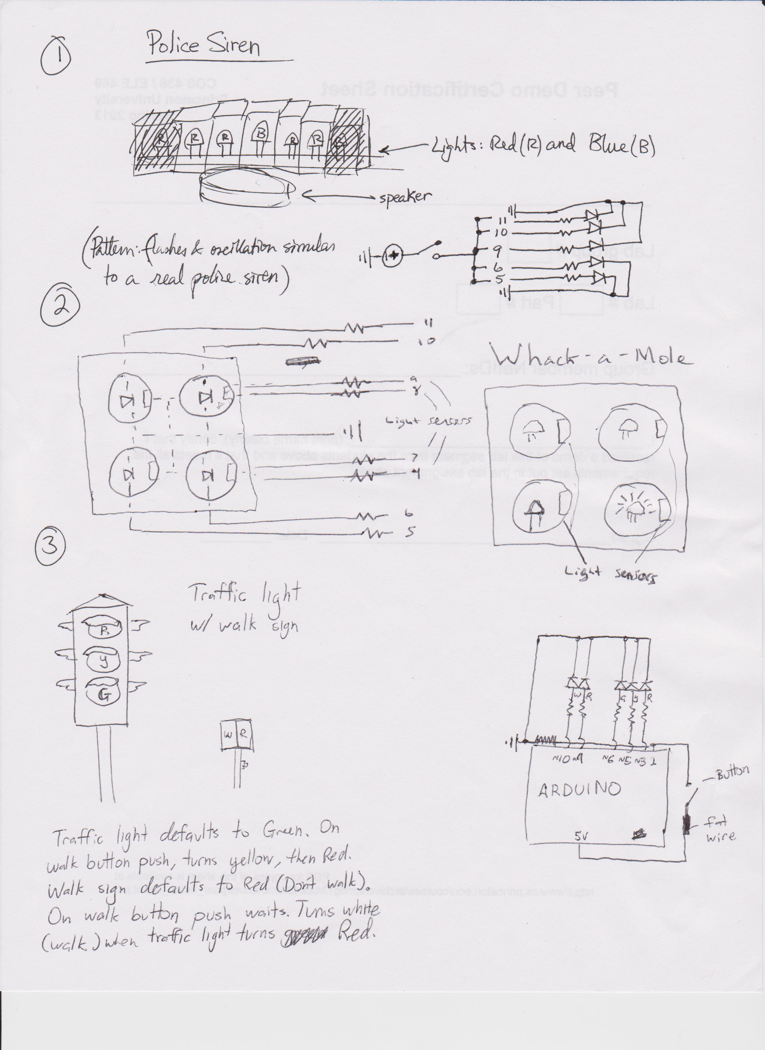
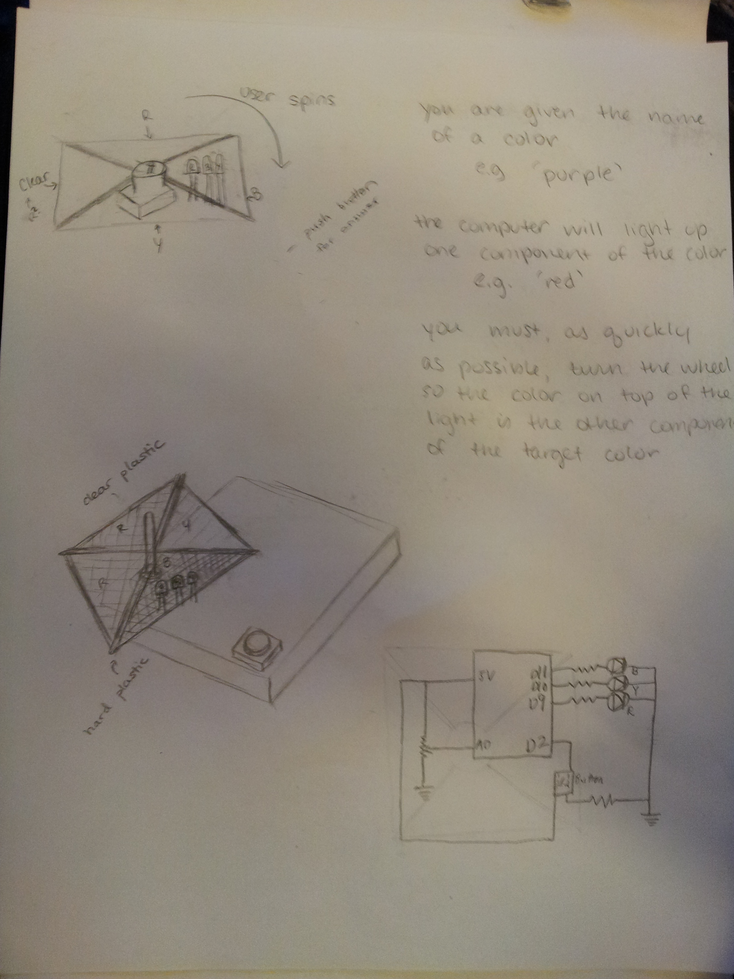
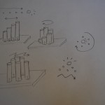
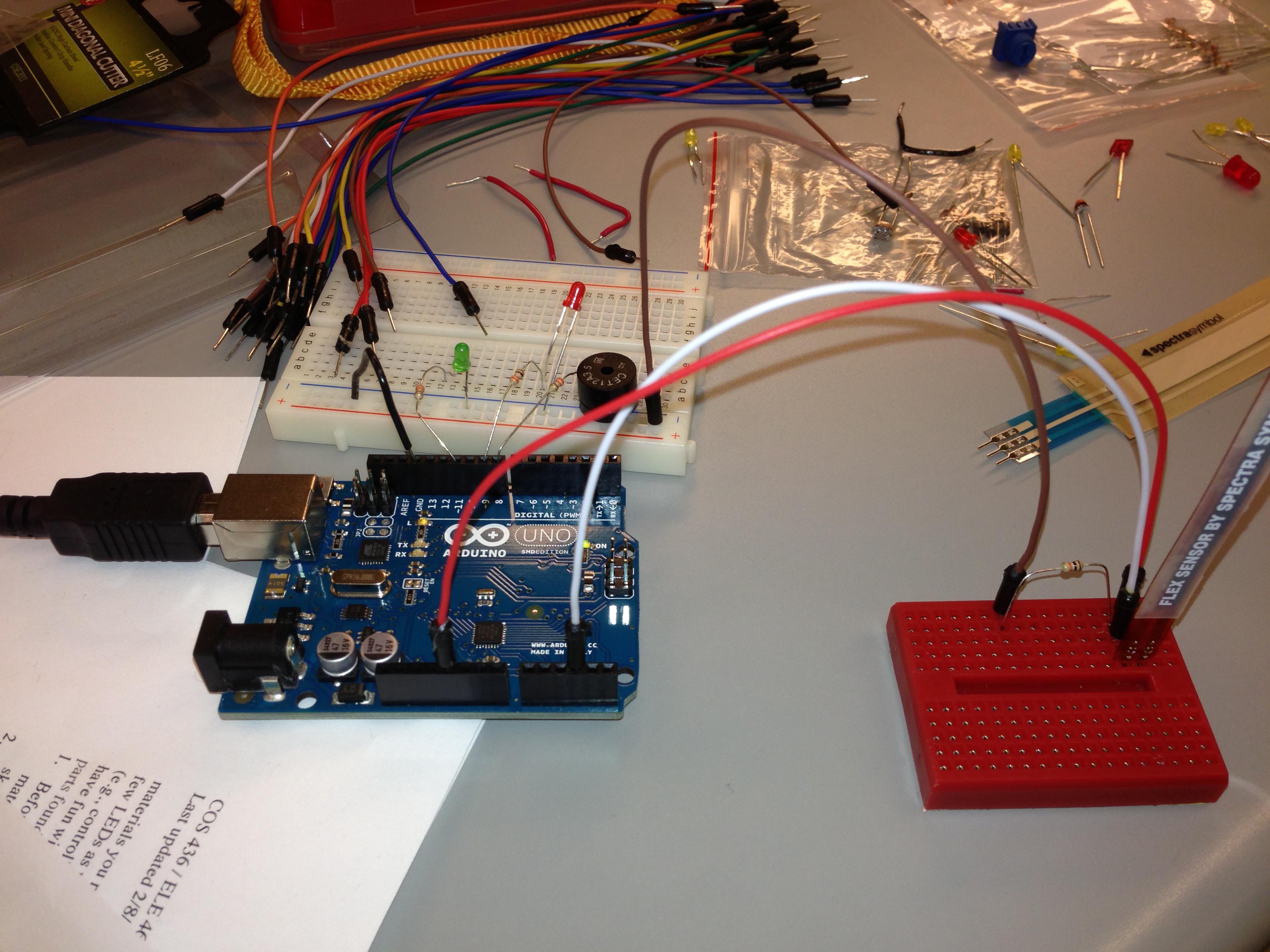
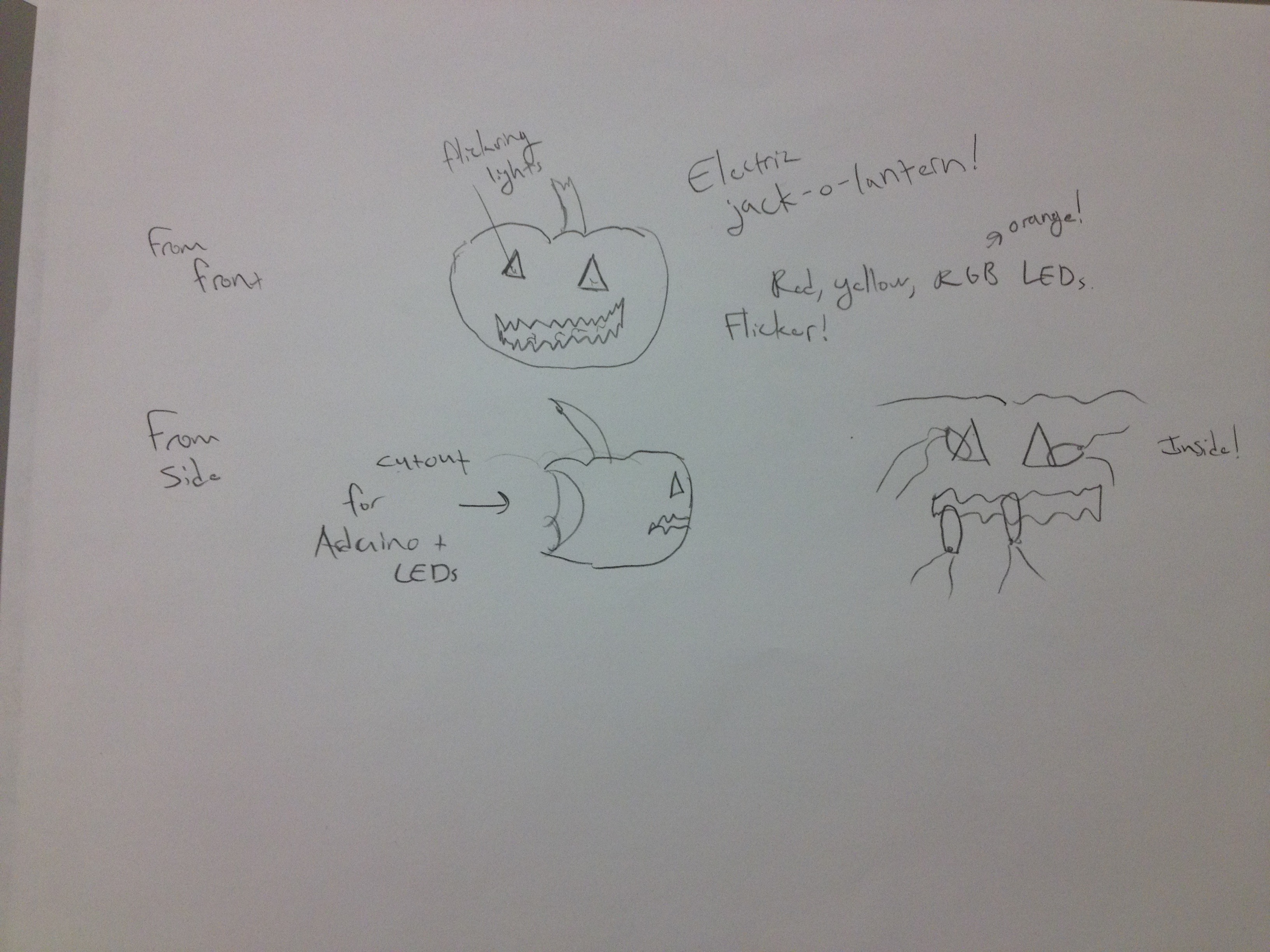
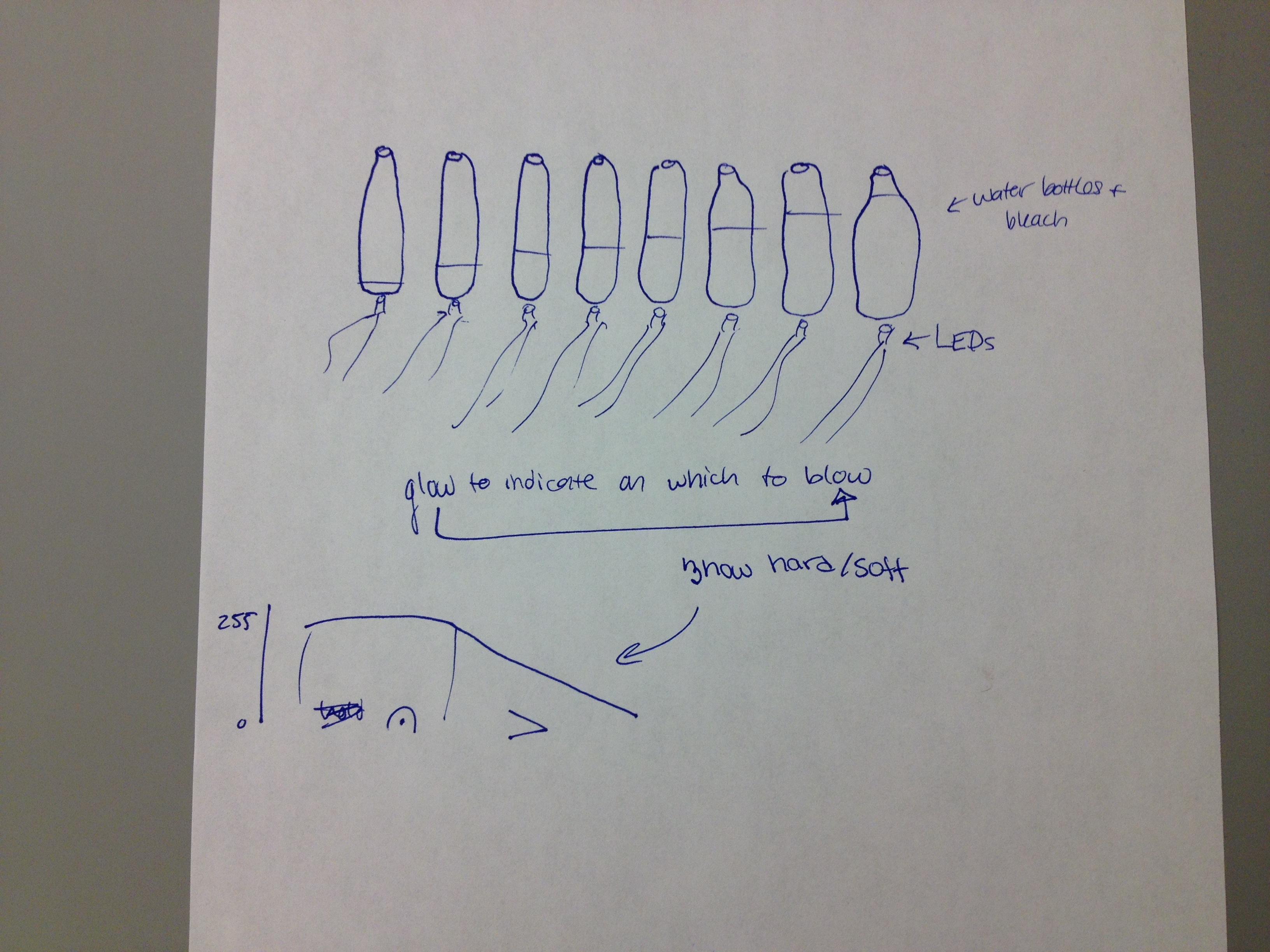
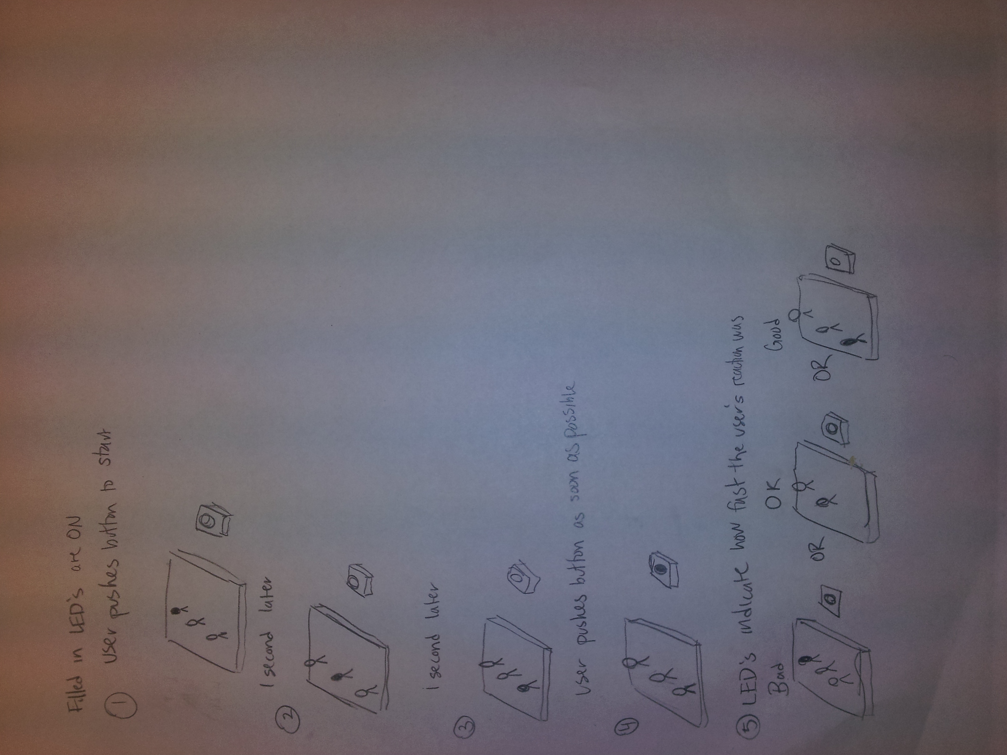
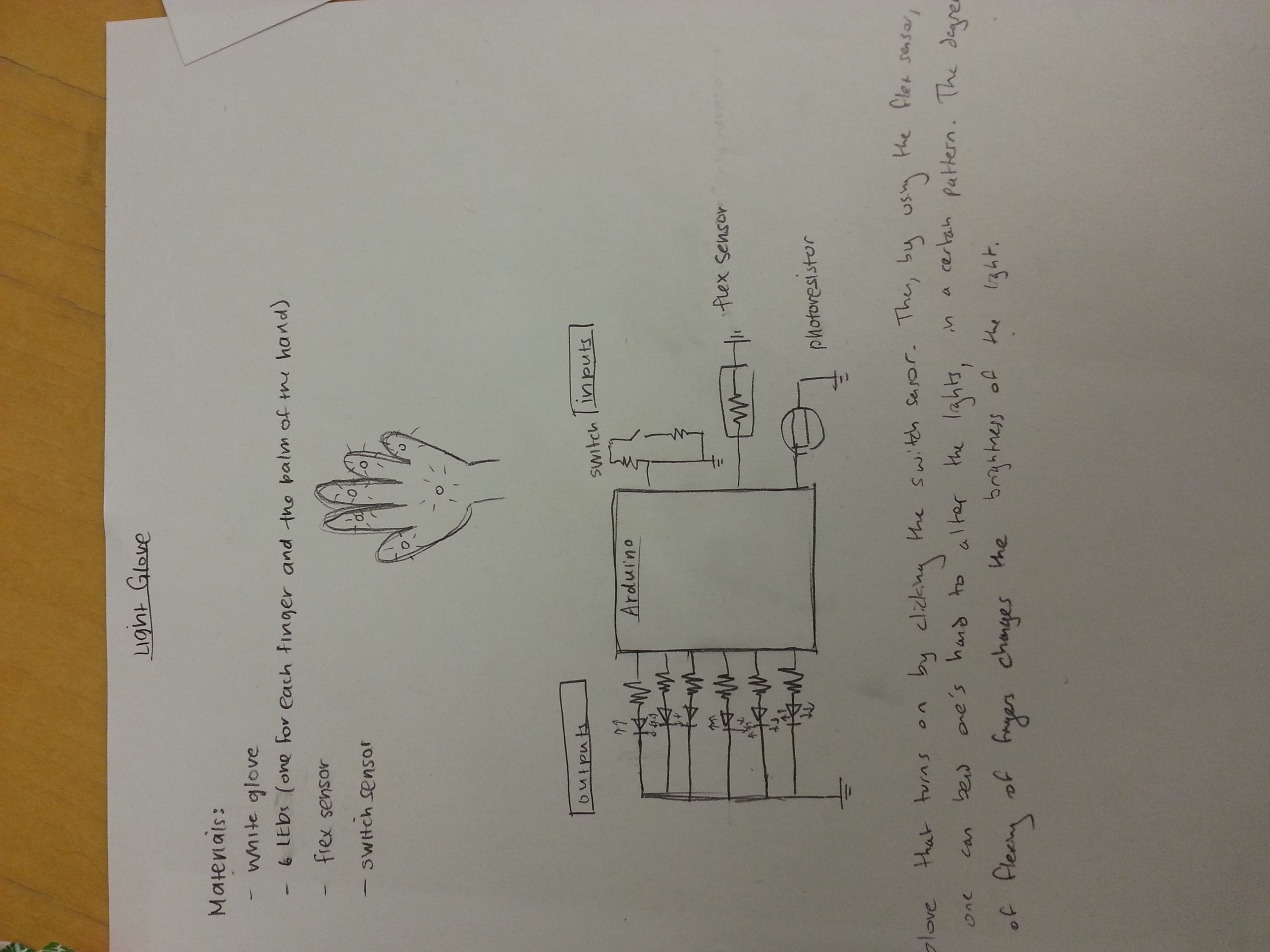
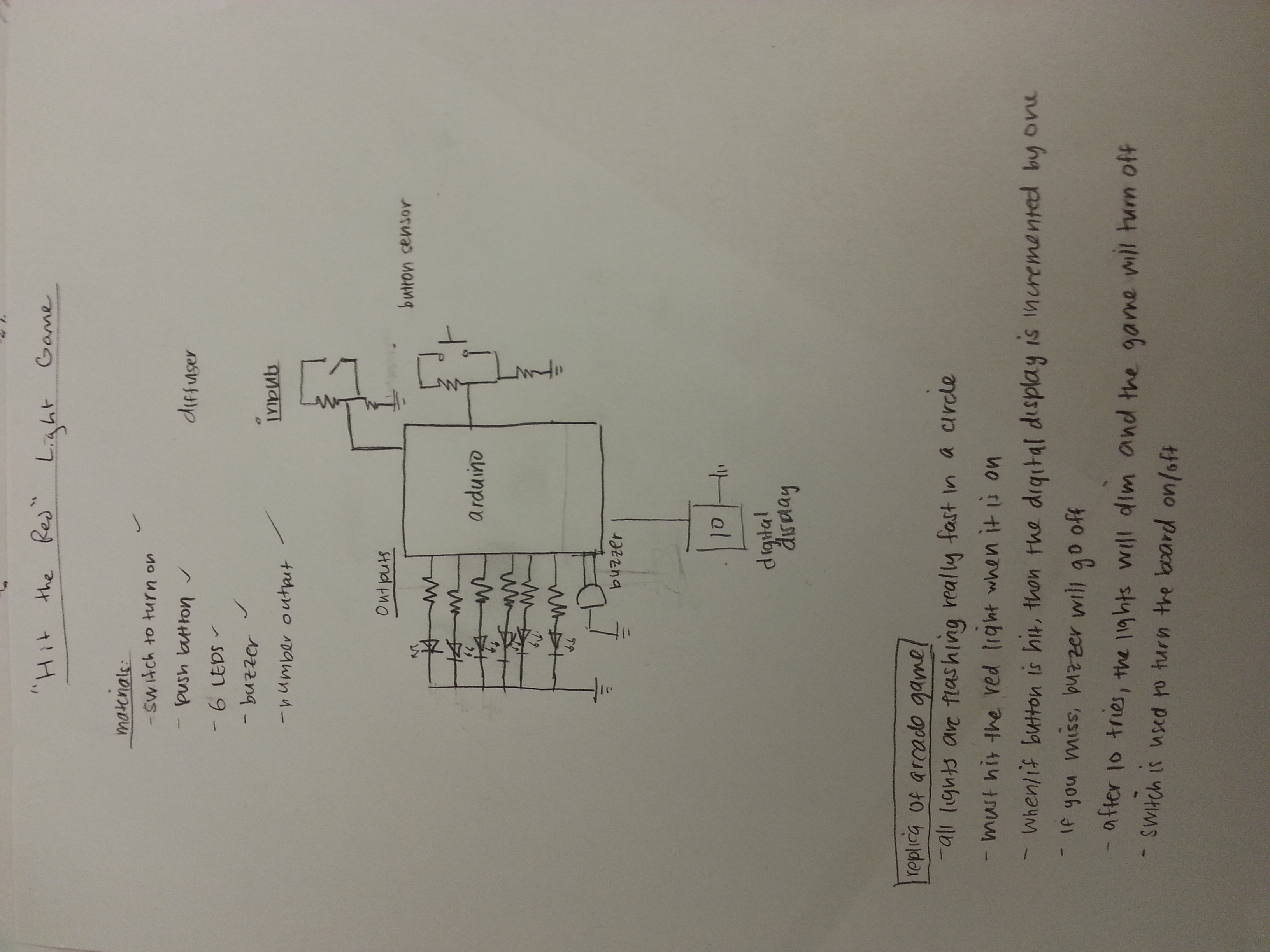
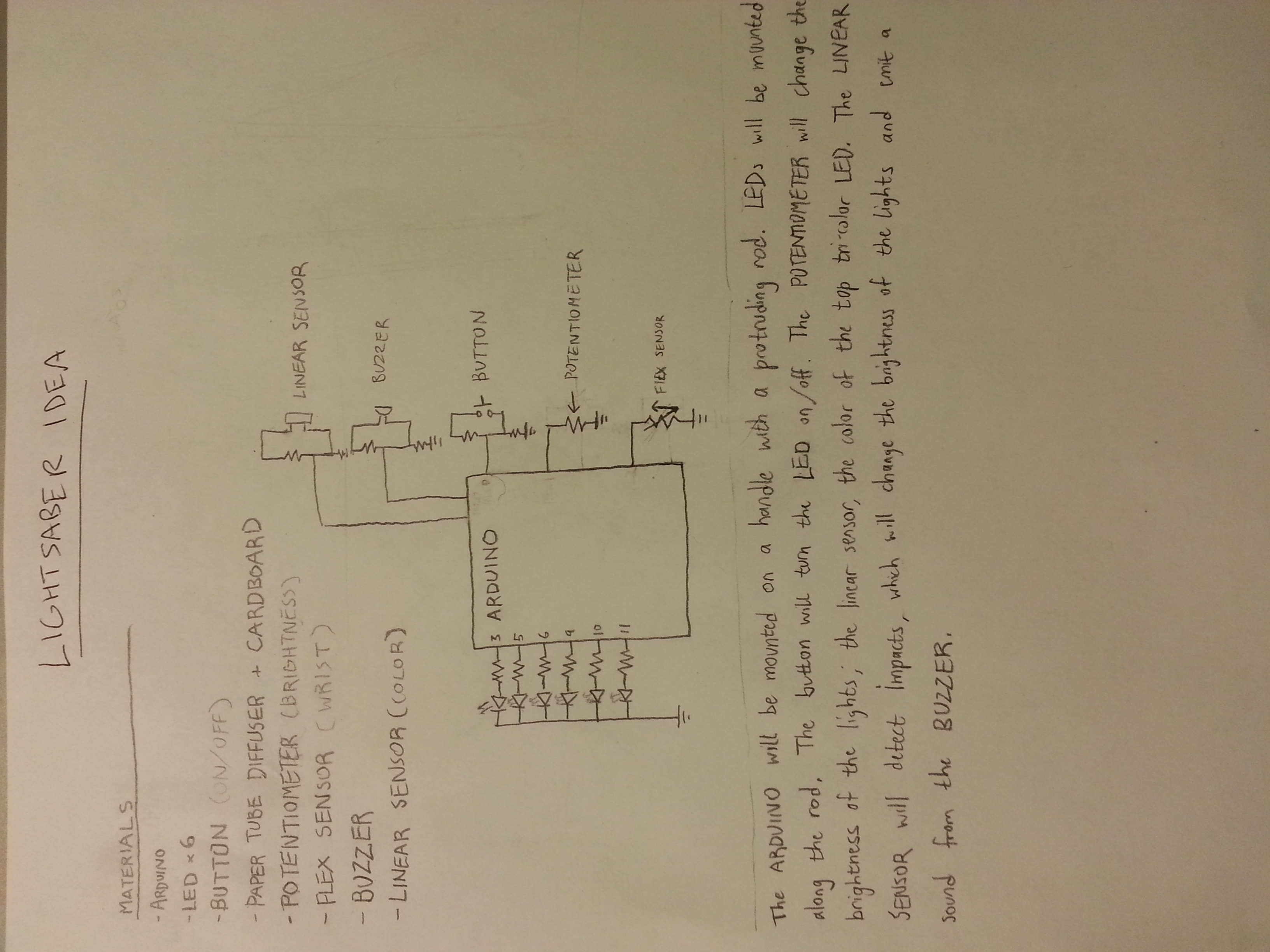
Early idea sketches:
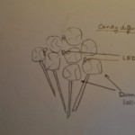
1) Gummi-Bear RGB color-mixer!
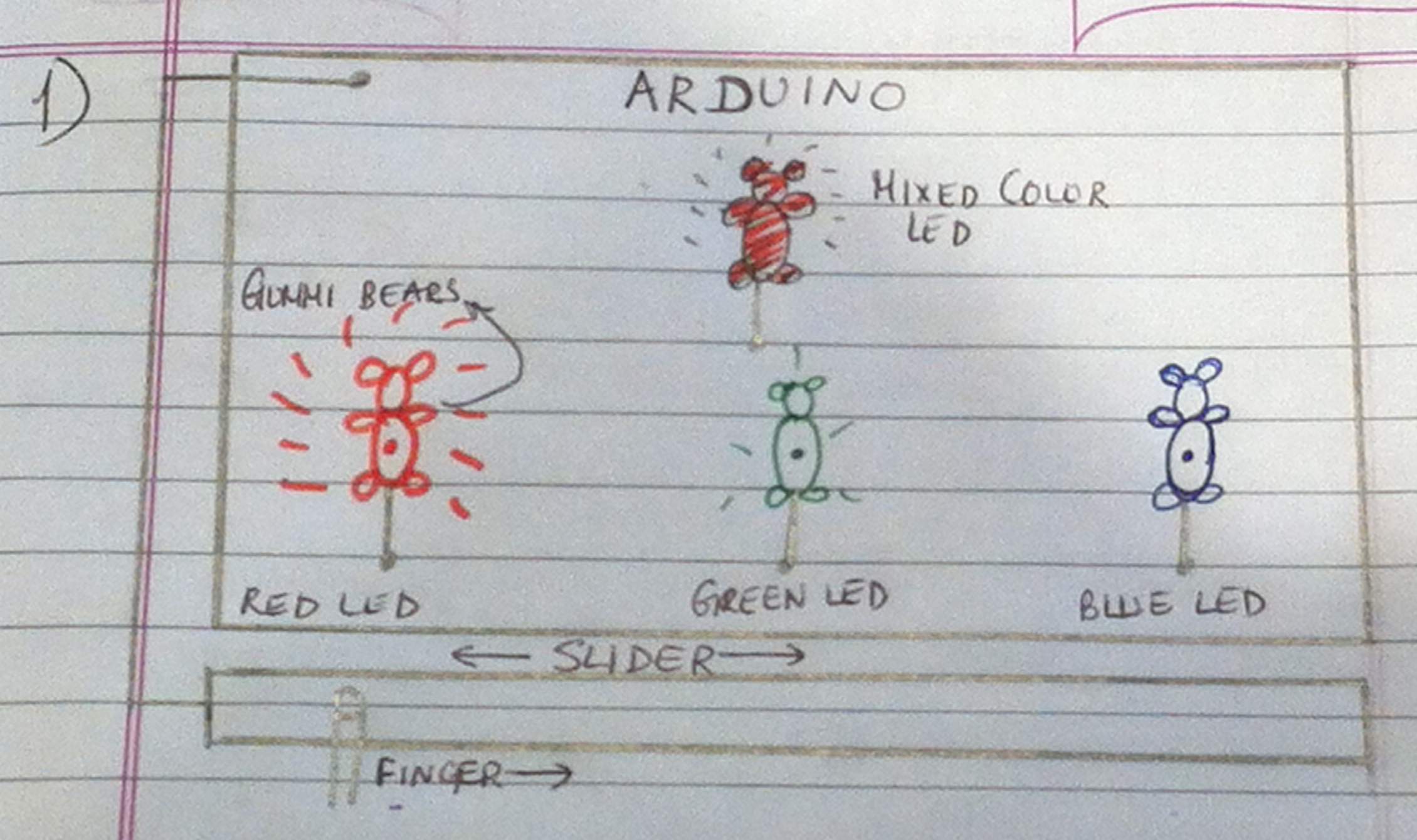
Sliding your finger on a slide-sensor transfers light between three R-G-B gummi bears!
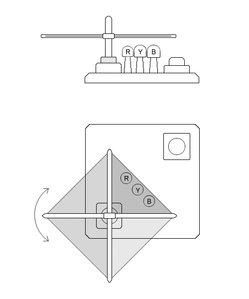
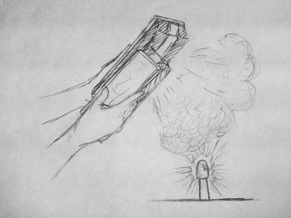
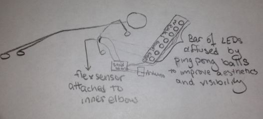
3) The “Waker-Upper”
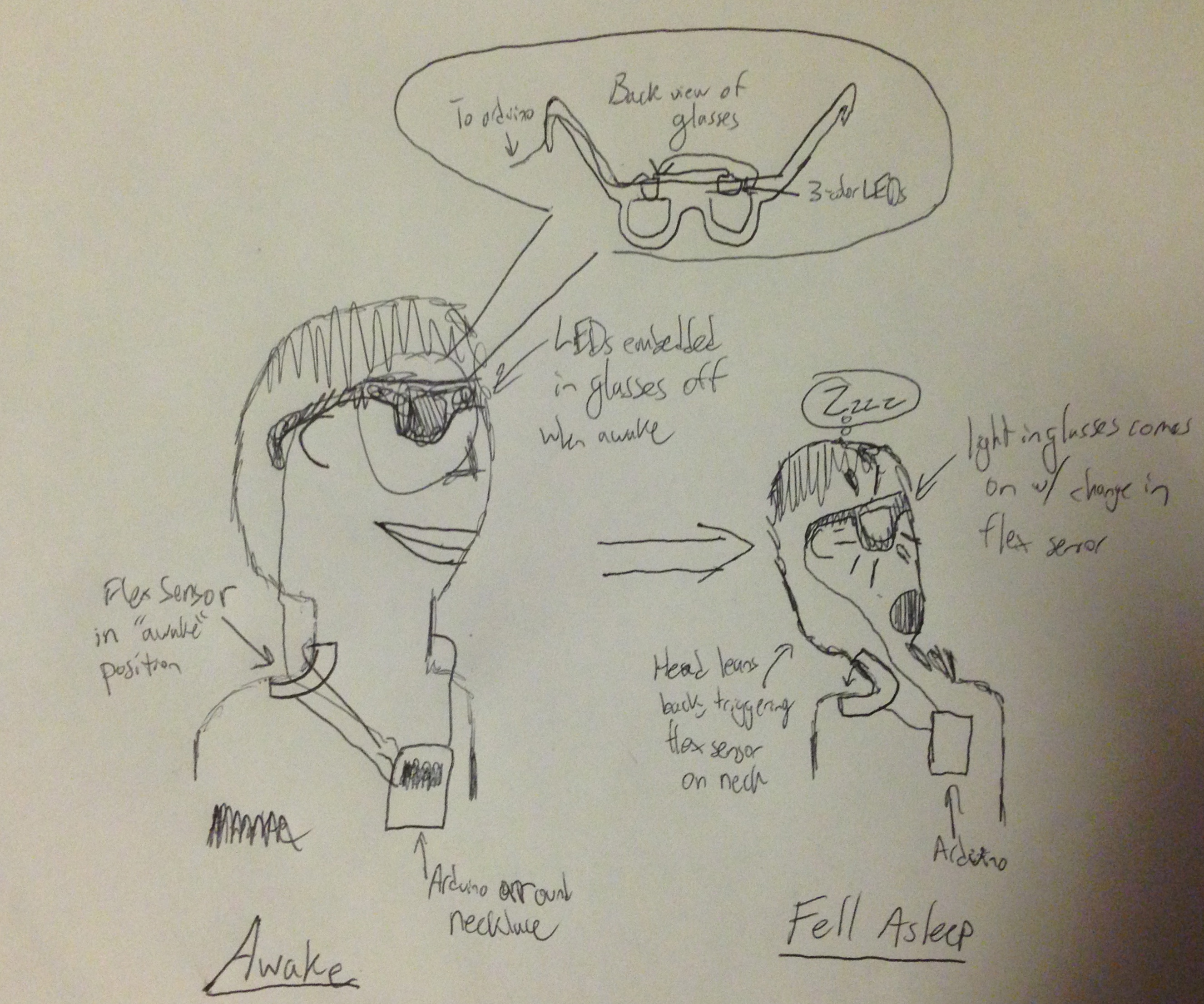
A device that detects when your head leans, indicating that you fell asleep. Triggers LEDs in glasses to wake you up
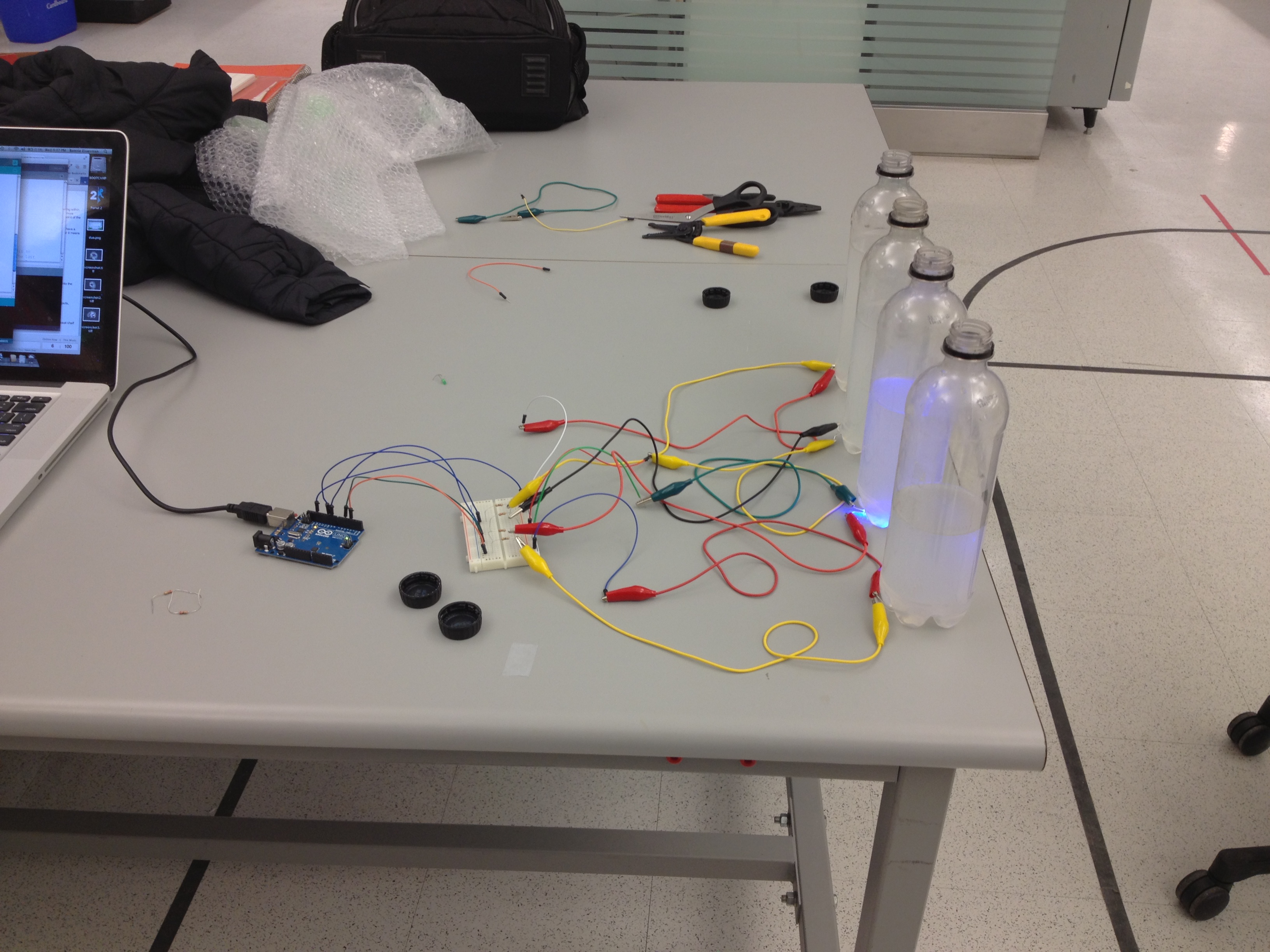
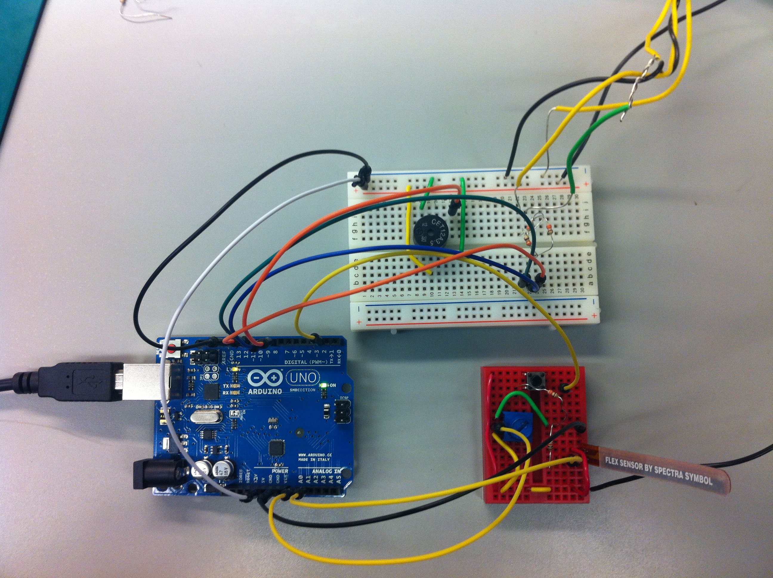
Idea actually implemented:
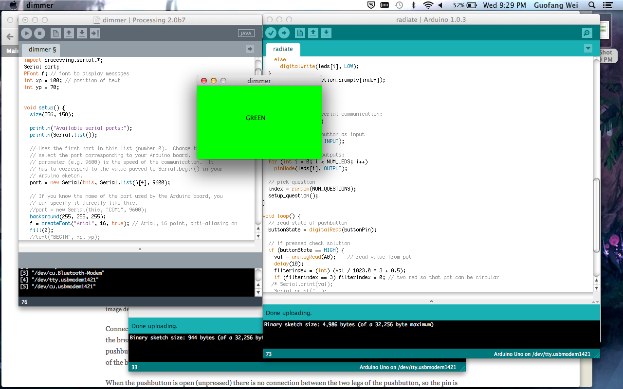
We built a color matching game. The computer will generate a random color, then the user must use a touch sensitive slide control to try and match that color. When the user thinks that they have matched the color they press a button to accept. A blue LED will flash if the colors match and a red LED will flash if they do not match. The game then resets and repeats. There is no score, or meta-game these can be added to later models if desired. The difficulty of the game can be adjusted to change how closely the colors must match. This first model of the game was built with a sensor which was not ideal for the task – the resistance characteristic is exponential rather than linear depending where the user presses on it. The controls were adjusted to correct for this, but the next model should be built with a sensor with a linear characteristic to improve the feel of the user’s controls.
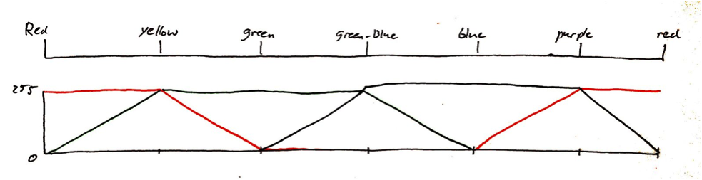
Graph showing linear mixing of colors as finger slides across the sensor.
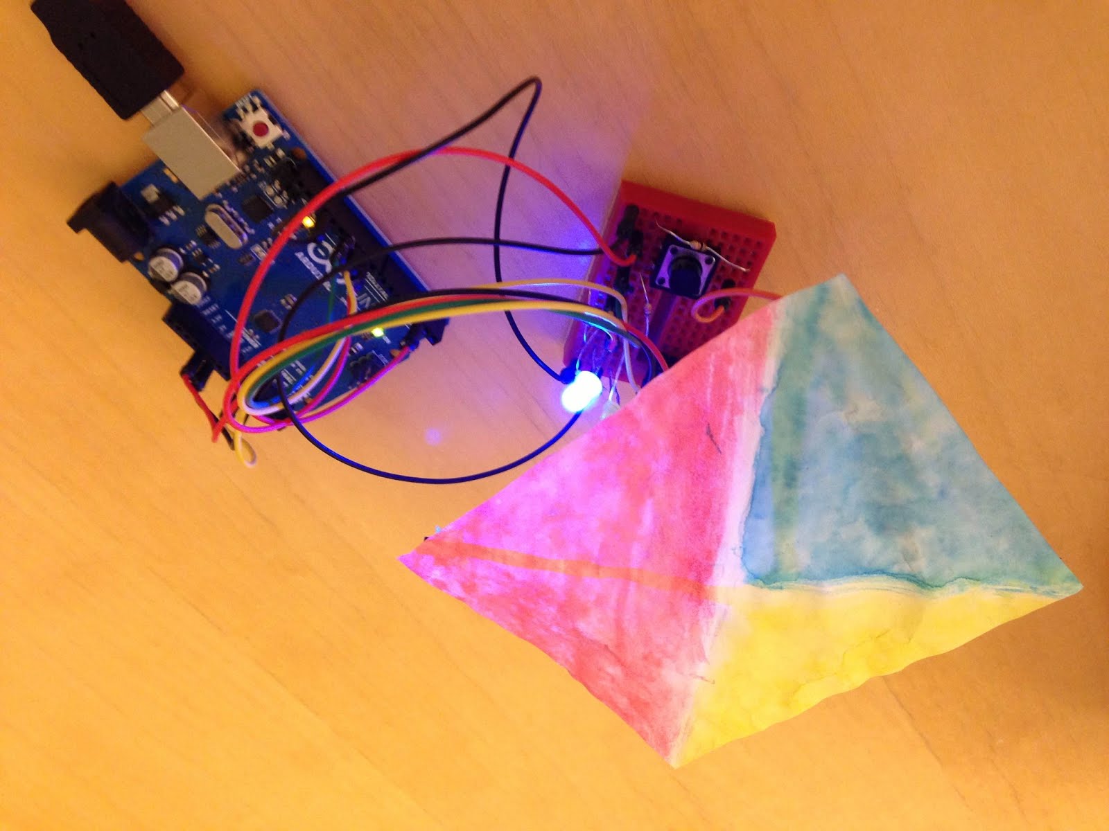
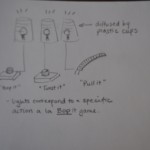
Sam explains gameplay:
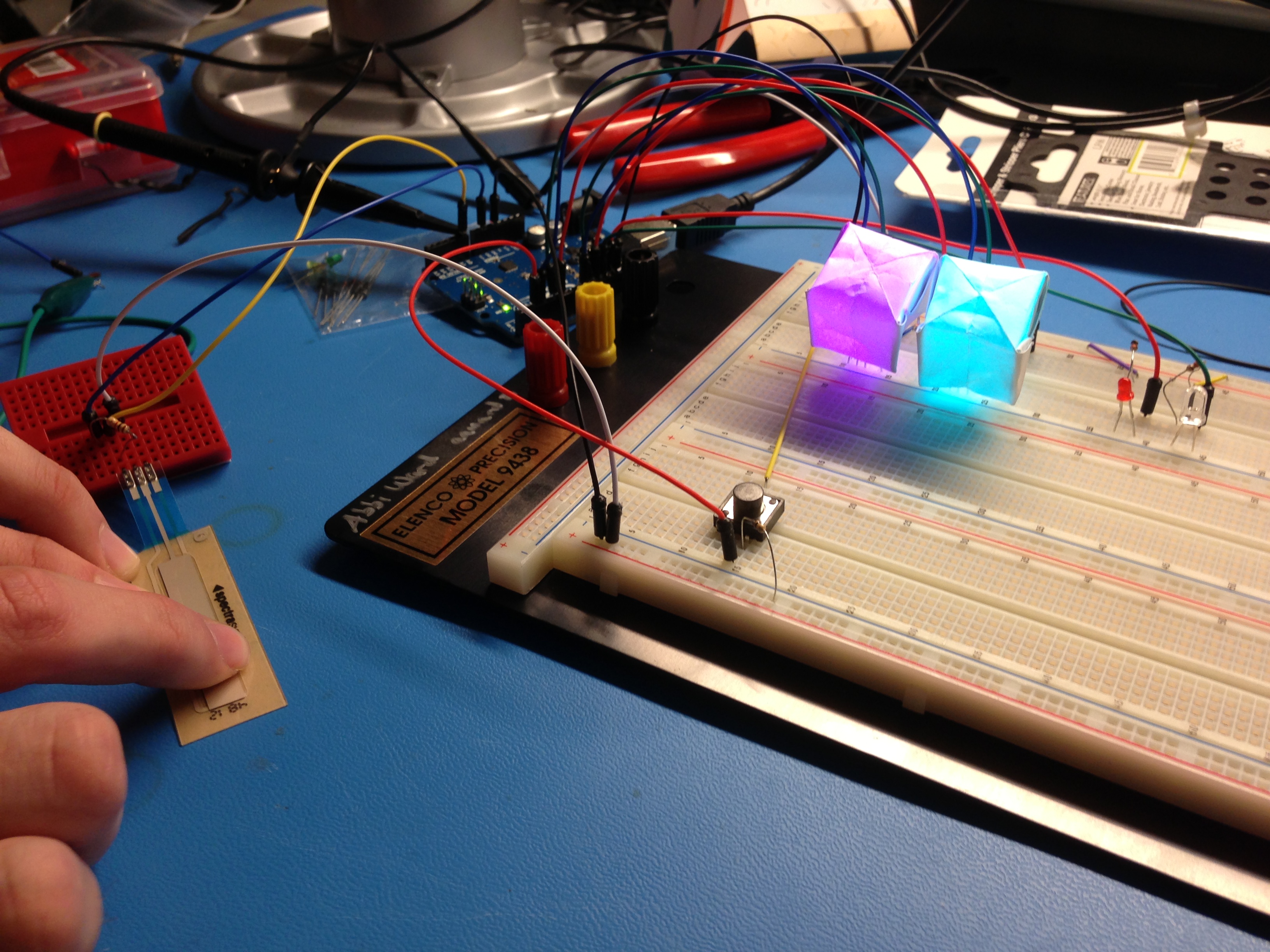
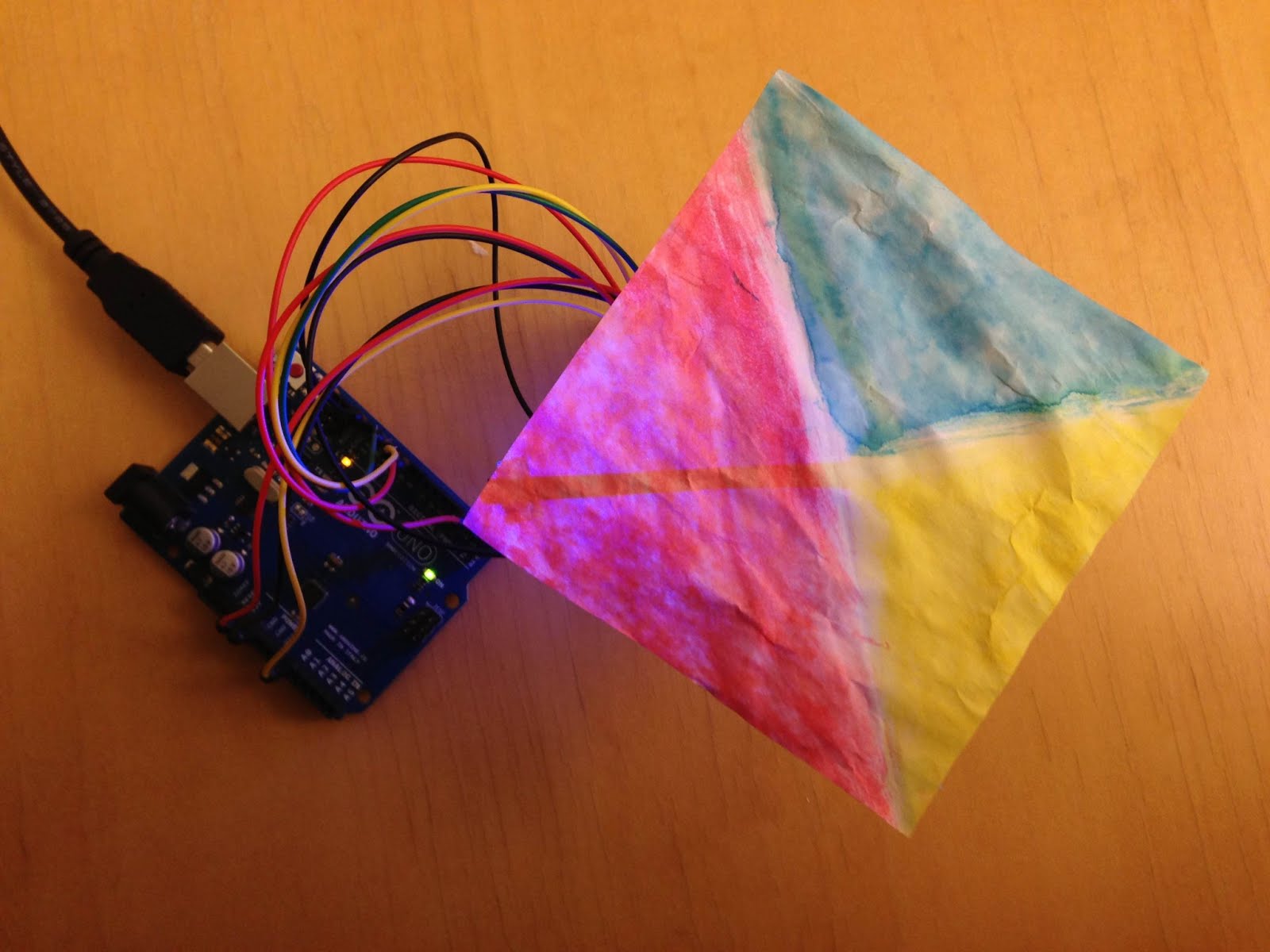
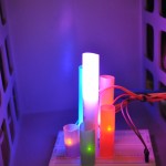
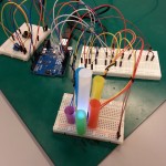
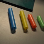
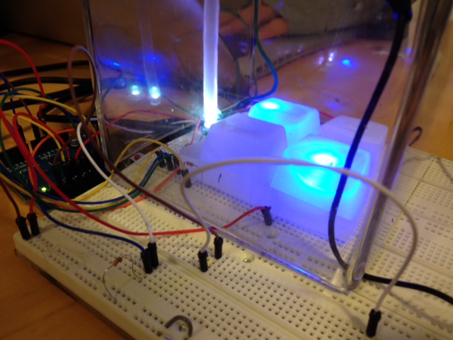
Player attempts to match right diffuser to left diffuser.
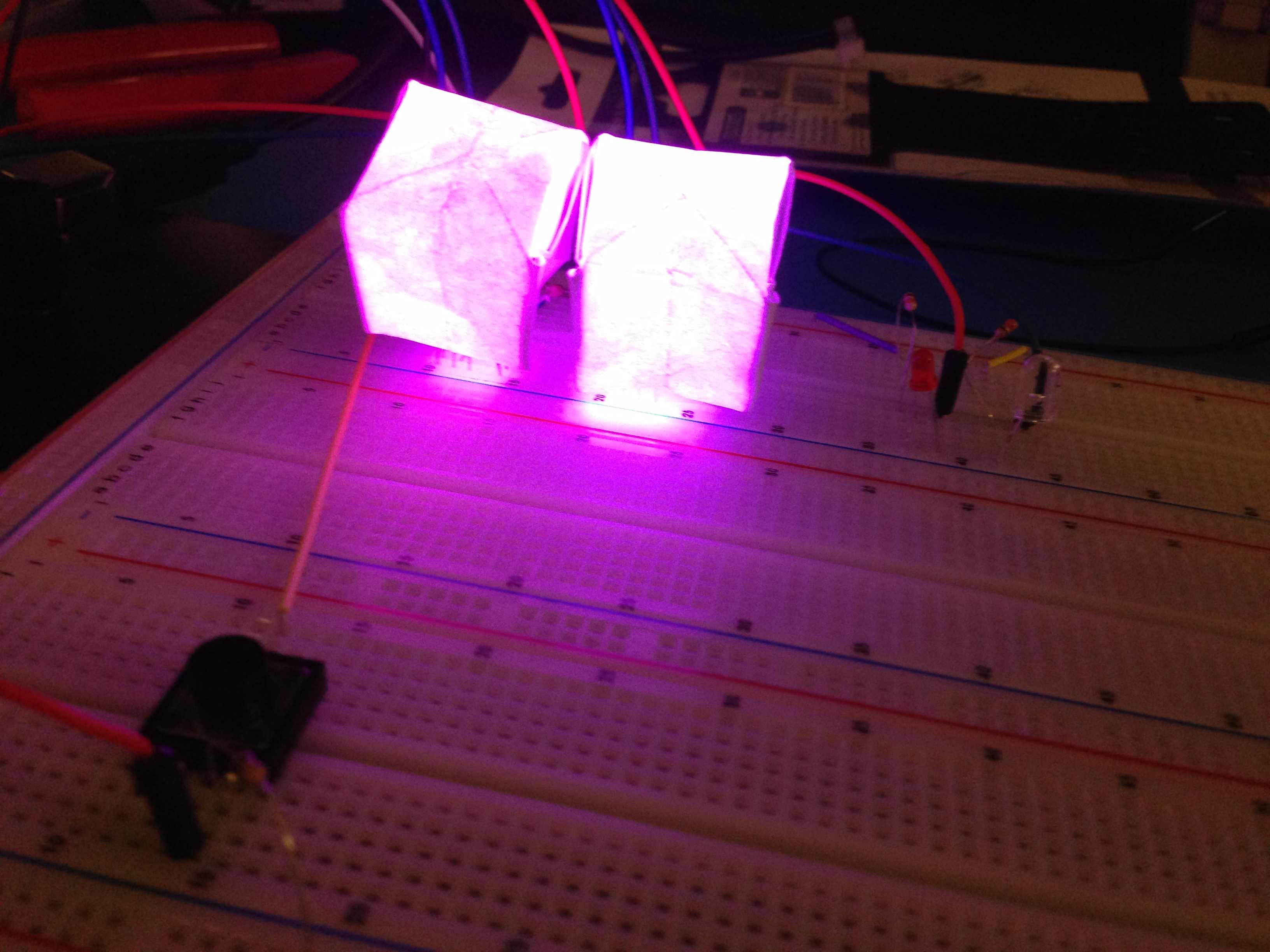
Diffuser shows off vibrant light in the dark
Parts:
Parts List
2 RGB LEDs
1 blue LED
1 red LED
8 330-Ohm Resistors
1 1-kOhm Resistor
1 10-kOhm Resistor (for the switch)
1 slider sensor
1 button switch
2 square sheets of paper for the diffusers
1 paper napkin
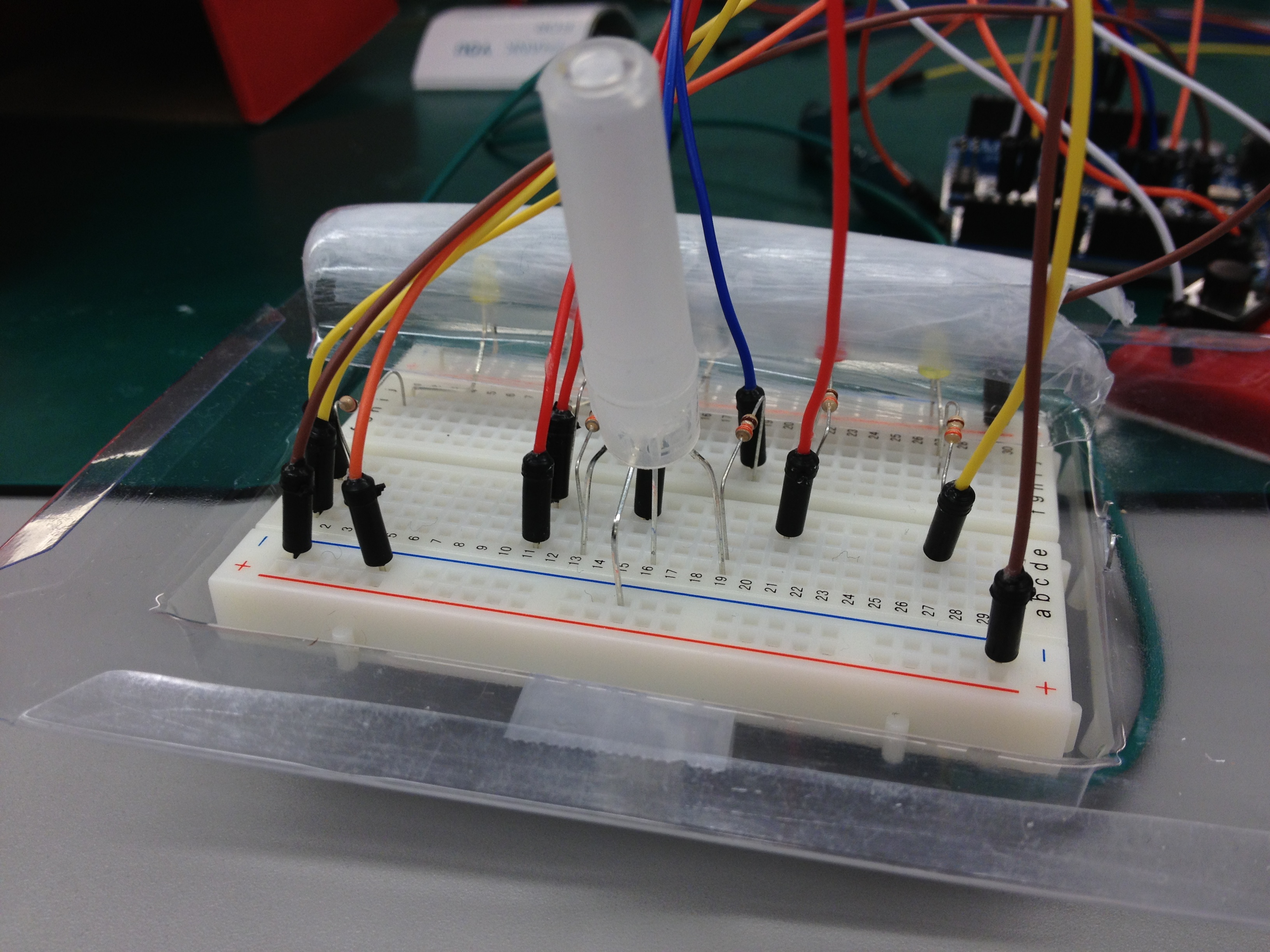
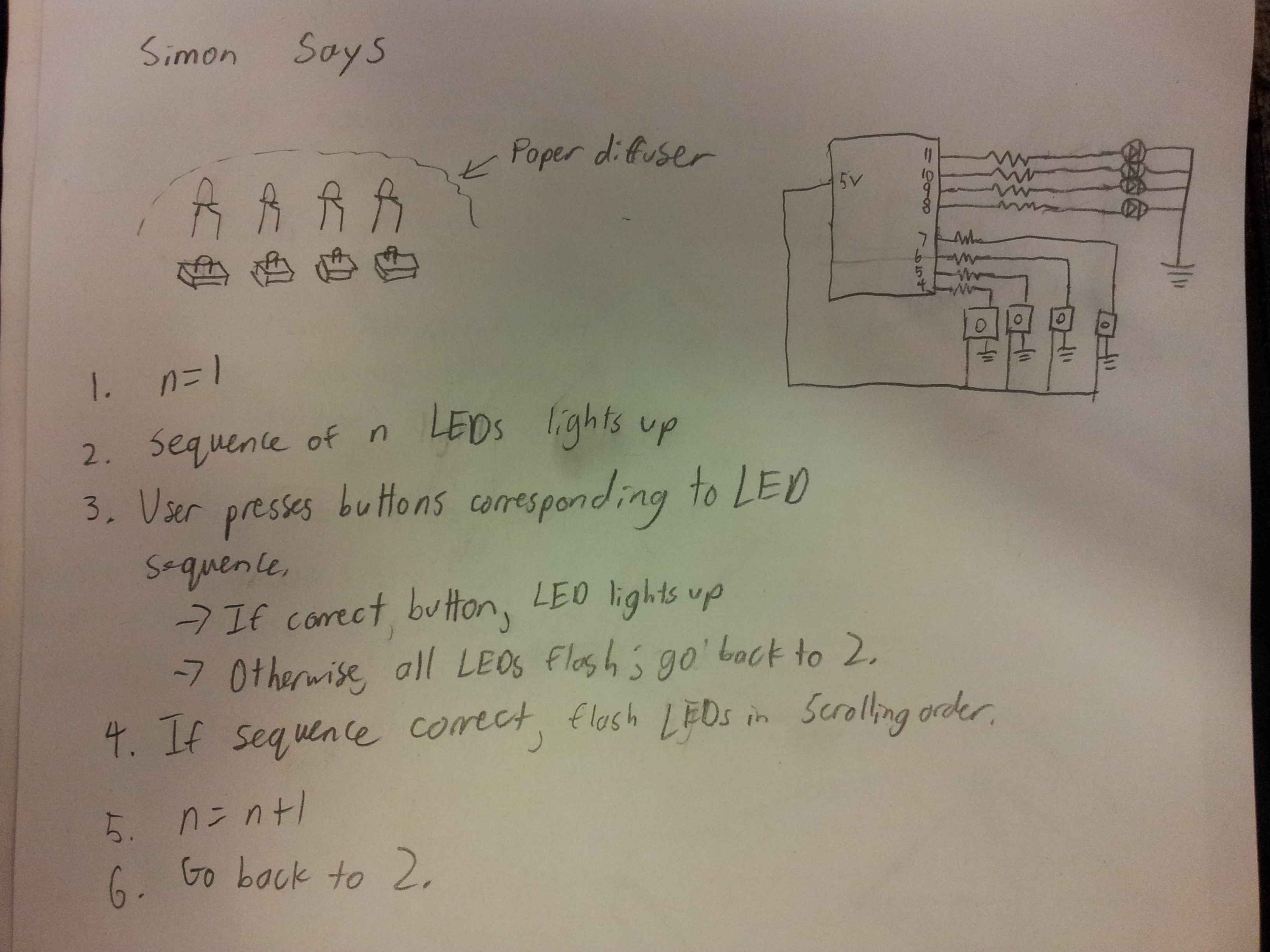
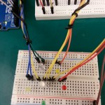
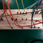
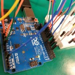
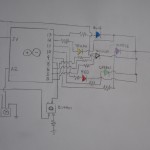
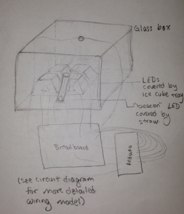
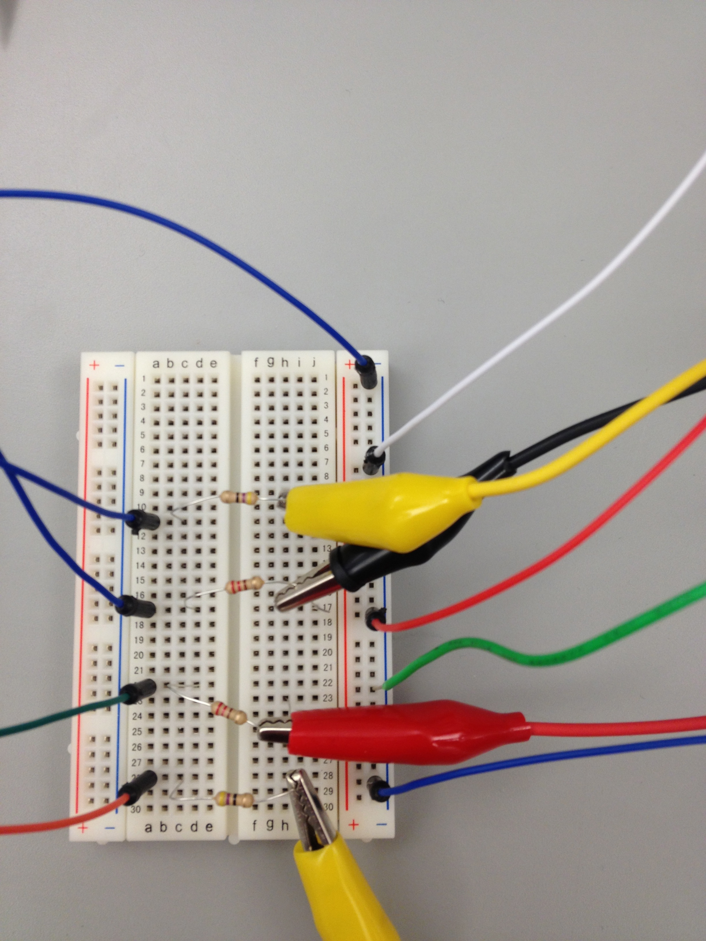
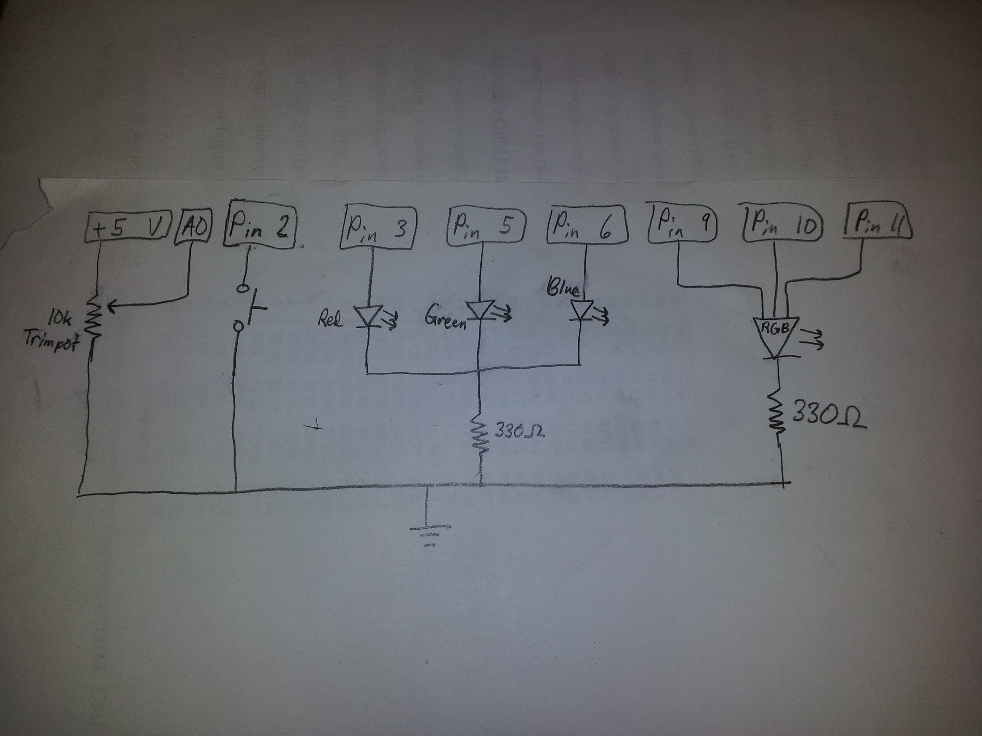
Instructions to recreate:
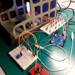
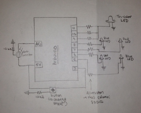
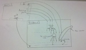
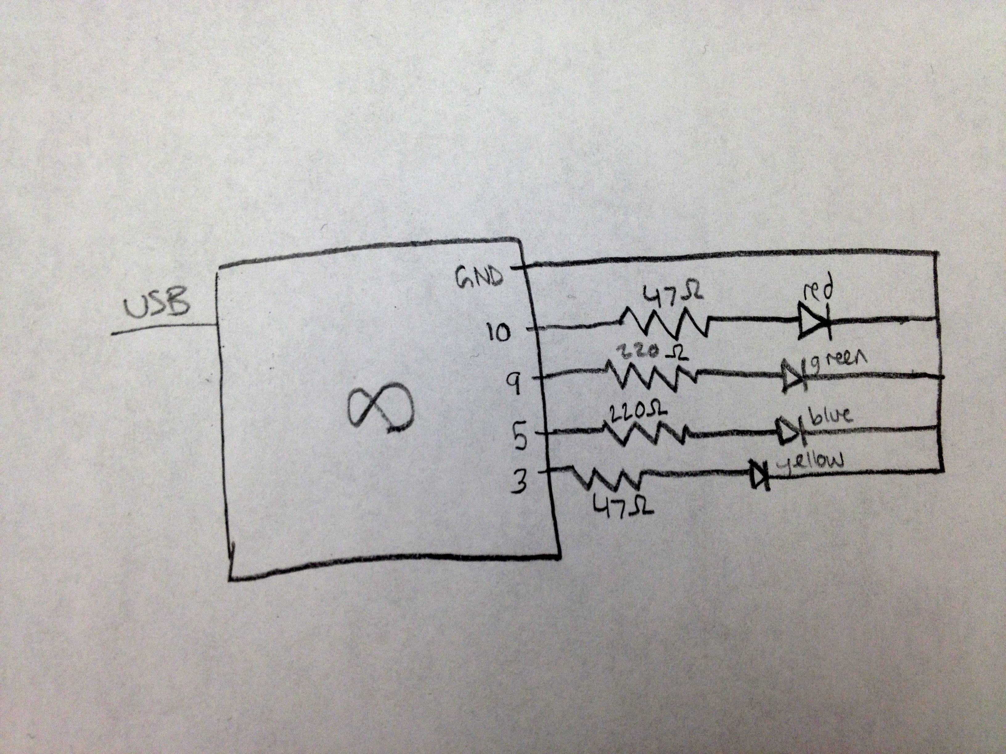
Follow the given schematic(below) to construct the circuit. The diffusers are built using small square pieces of paper (~3×3 inches) that are folded into origami paper ballons (see: http://www.youtube.com/watch?v=tSMLk_zGzf4). Cut a hole in the bottom of the balloon so that the LED can fit. Also, inside the balloon place a small sheet of 1-ply paper napkin to help diffuse the light. Finally, program the Arduino with the following code.
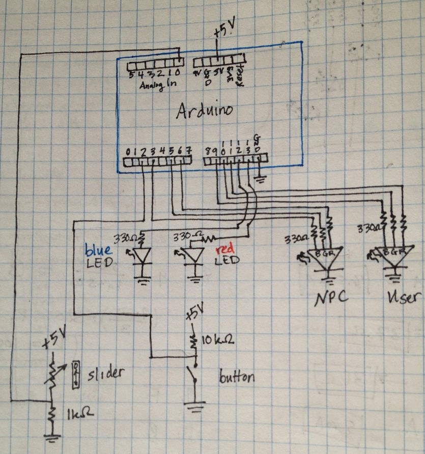
Schematic view of Color game
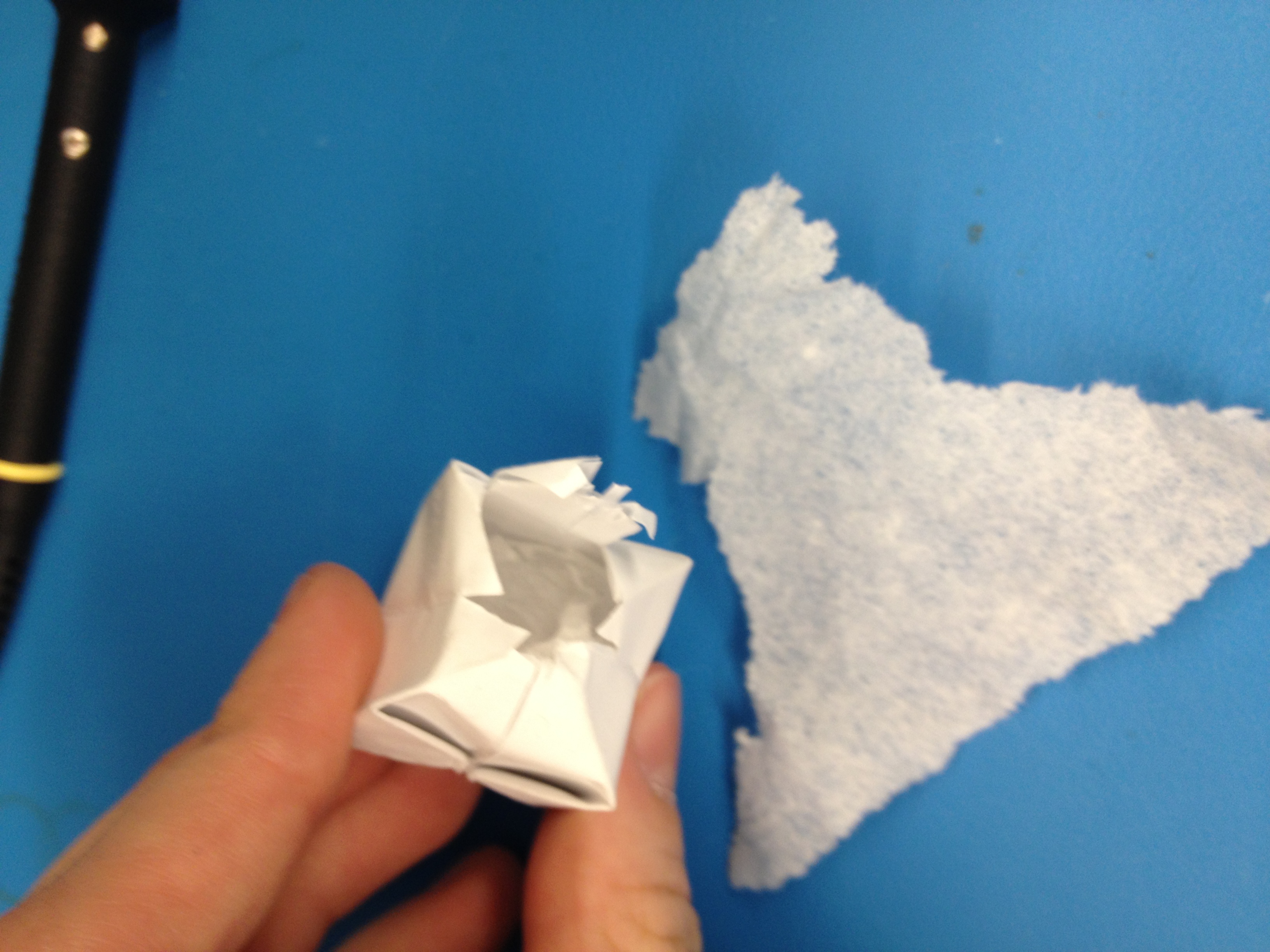
Close-up of diffuser
Code used for Arduino:
/*
* Names: Sam Payne, Abbi Ward, Dillon Reisman, Prerna Ramachandra
* Date: 2/10/13
* Class: COS 469, L0
*
* Description: Color Game -- player
*
* Hardware:
* 2 RGB LEDs, 1 red LED, 1 green LED
* 1 slider sensor
* 1 button switch
*
*/

//pin assignments
//user LED
int redUser = 11;
int greenUser = 10;
int blueUser = 9;
//NPC LED
int redNPC = 6;
int greenNPC = 5;
int blueNPC = 3;
//victory indicators
int redLED = 13;
int greenLED = 12;
//analog in's
int sensorPin = A0;

//colors assigned user and computer
int targetRed;
int targetGreen;
int targetBlue;
int selRed;
int selGreen;
int selBlue;

int buttonPin = 2;
int buttonState = HIGH;
int sensorValue = 0;

int tolerance = 64; //this can be adjusted for difficulty (lower = more difficult)
int victory = 0;

void setup()  {
  pinMode(buttonPin, INPUT);
}

void loop()  {
  //generate random color
  targetRed = random(0,255);
  targetGreen = random(0,255);
  targetBlue = random(0,255);

  //ensure that color can be selected by slider
  if((targetRed <= targetGreen) && (targetRed <= targetBlue))
  targetRed = 0;
  else if((targetGreen < targetRed) && (targetGreen < targetBlue))
  targetGreen = 0;
  else
  targetBlue = 0;

  //ensure that color can be selected by slider
  if((targetRed >= targetGreen) && (targetRed >= targetBlue))
  targetRed = 255;
  else if((targetGreen > targetRed) && (targetGreen > targetBlue))
  targetGreen = 255;
  else
  targetBlue = 255;

  analogWrite(redNPC, targetRed);
  analogWrite(greenNPC, targetGreen);
  analogWrite(blueNPC, targetBlue);

  selRed = 0;
  selGreen = 0;
  selBlue = 0;
  //adjust user input
  while(1) {
     //read user input color
     sensorValue = analogRead(sensorPin);

     //set display colors based on slider
     setColors_slider(sensorValue);

     //display user color
     analogWrite(redUser, selRed);
     analogWrite(greenUser, selGreen);
     analogWrite(blueUser, selBlue);

     //when user presses accept, save color
     buttonState = digitalRead(buttonPin);

     if(buttonState == LOW) {
        break;
     }

  }
  victory = 1;
  //determine if we are within tolerance
  if(selRed > (targetRed + tolerance)) victory = 0;
  if(selRed < (targetRed - tolerance)) victory = 0;
  if(selGreen > (targetGreen + tolerance)) victory = 0;
  if(selGreen < (targetGreen - tolerance)) victory = 0;
  if(selBlue > (targetBlue + tolerance)) victory = 0;
  if(selBlue < (targetBlue - tolerance)) victory = 0;

  //if user color is in tolerance, flash green LED
  if(victory == 1) {
    for(int i = 0; i < 5; i++) {
      digitalWrite(greenLED, HIGH);
      delay(100);
      digitalWrite(greenLED, LOW);
      delay(100);
    }
  } else {
  //else flash red LED
    for(int i = 0; i < 5; i++) {
      digitalWrite(redLED, HIGH);
      delay(100);
      digitalWrite(redLED, LOW);
      delay(100);
    }
  }
}

// reads in the value from the slider and sets the RGB LED
/* This function maps from 1D on the slider to 3D (R, G, B)
At any time, one of the 3 dimensions is 0, and another is 255.
The last scales linearly within particular ranges of color.
*/
void setColors_slider(int readValA) {
  int readVal = map(readValA, 100, 550, 160, 256);
  /* linear scale
  int R = 160;
  int Y = 176;
  int G = 192;
  int GB = 208;
  int B = 224;
  int P = 240;
  int RH = 256;
  */
  // exponential scale - wrong way
  /*
  int R = 160;
  int Y = 193;
  int G = 215;
  int GB = 230;
  int B = 239;
  int P = 248;
  int RH = 256;
  */
  // exponential scale - right way
  // 33, 22, 15, 9, 9, 8
  int R = 160;
  int Y = 168;
  int G = 177;
  int GB = 186;
  int B = 201;
  int P = 223;
  int RH = 256;
  //set Red
  if(readVal <= Y)
     selRed = 255;
  else if(readVal > Y && readVal <= G)
     selRed = (255 - ((readVal - Y) * 255/(G-Y)));
  else if(readVal > B && readVal <= P)
    selRed = ((readVal - B) * 255/(P-B));
  else if((readVal > P && readVal <= RH) || readVal > RH)
    selRed = 255;
  else
    selRed = 0;

  //set green
  if(readVal > Y && readVal <= GB)
    selGreen = 255;
  else if(readVal <= Y && readVal > R)
    selGreen = ((readVal - R) * 255/(Y-R))-1;
  else if(readVal > GB && readVal <= B)
    selGreen = (255 - ((readVal - GB) * 255/(B-GB)));
  else
    selGreen = 0;

  //set blue
  if(readVal > G && readVal <= GB)
    selBlue = ((readVal - G) * 255/(GB-G));
  else if(readVal > GB && readVal <= P)
    selBlue = 255;
  else if(readVal > P && readVal <= RH)
    selBlue = (255 - ((readVal - B) * 255/(RH-P)));
  else
    selBlue = 0;
}